Page is loading ...

Page 1 of 35
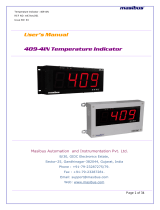
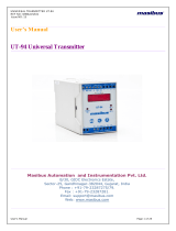
User’s Manual
D
DI
IG
GI
IT
TA
AL
L
T
TE
EM
MP
PE
ER
RA
AT
TU
UR
RE
EC
CO
ON
NT
TR
RO
OL
LL
LE
ER
R
5
50
00
02
2U
U-
-P
P
Masibus Automation & Instrumentation Pvt. Ltd.
B/30, GIDC Electronics Estate,
Sector-25, Gandhinagar-382044, Gujarat, India
+91 79 23287275-77 +91 79 23287281
Email: support@masibus.com
Web: www.masibus.com

TEMPERATURE CONTROLLER 5002U-P
REF NO: m55A/om/201
Issue NO: 05
Page 2 of 35
Contents
1. INTRODUCTION .................................................................................. 4
Foreword ................................................................................................................ 4
Notice ..................................................................................................................... 4
Trademarks ............................................................................................................ 4
Checking the Contents of the Package .................................................................. 4
Product Ordering Code .......................................................................................... 4
List of Accessories ................................................................................................. 5
Safety Precautions ................................................................................................. 5
2. INSTALLATION DETAILS .................................................................. 6
2.1 How to Install .................................................................................................... 6
2.2 External Dimensions and Panel Cutout Dimensions ....................................... 7
2.3 How to connect wires ...................................................................................... 8
3. HARDWARE SPECIFICATION DETAILS ........................................... 9
3.1 Inputs............................................................................................................... 9
3.2 Display & Keys ................................................................................................ 9
3.3 Output............................................................................................................... 9
3.4 Communication Details .................................................................................. 10
3.5 Power Supply ................................................................................................ 10
3.6 Physical ......................................................................................................... 10
3.7 Environmental ............................................................................................... 10
3.8 Special Feature ............................................................................................. 11
4. WIRING DIAGRAM ........................................................................... 11
4.1 Back Plate Wiring Detail ................................................................................ 11
4.2 Transmitted Power Supply Wiring Diagram .................................................... 12
5. FRONT PANEL DETAILS ................................................................. 12
5.1 Key Function Description ............................................................................... 13
6. MENU LAYOUT ................................................................................ 15
6.1 Run Time Indication/Function ........................................................................ 15
6.2 Set Point Setting ............................................................................................ 15
6.3 LEVEL – 1 ..................................................................................................... 15
6.4 LEVEL - 2 ...................................................................................................... 16
6.5 LEVEL - 3 ...................................................................................................... 18

TEMPERATURE CONTROLLER -5002U-P
REF NO: m55A/om/201
Issue NO: 05
Page 3 of 35
6.6 Calibration ..................................................................................................... 20
6.7 Factory Reset Parameters ............................................................................. 21
7. PARAMETER FLOW CHART ............................................................ 22
8. ALARMS ............................................................................................ 24
9. CONTROL FUNCTION DETAILS ....................................................... 26
10. CALIBRATION PROCEDURE.......................................................... 28
10.1 Ambient temperature adjustment ................................................................ 28
10.2 PV input sensor calibration .......................................................................... 29
10.3 Retransmission1 and Retransmission2 output calibration (Voltage/current
output) .................................................................................................................. 29
11. COMMUNICATION DETAILS.......................................................... 30
11.1 Function codes use for Modbus .................................................................. 30
11.2 Exception responses for Modbus ................................................................ 30
11.3 Modbus parameters .................................................................................... 30
12. APPENDIX ...................................................................................... 33
12.1 Troubleshooting ............................................................................................ 33
12.2 PV Input Status Display During Burnout Condition ....................................... 34
12.3 Retransmission Output Table for OPEN /OVER /UNDER Condition ............ 34
12.4 Retransmission Output1 Type Selection Settings ........................................ 35
12.5 Relay Logic ................................................................................................... 35

TEMPERATURE CONTROLLER 5002U-P
REF NO: m55A/om/201
Issue NO: 05
Page 4 of 35
1.INTRODUCTION
Foreword
Thank you for purchasing 5002U-P Temperature controller. This manual describes the
basic functions and operation methods of 5002U-P. Please read through this user’s
manual carefully before using the product.
Notice
The contents of this manual are subject to change without notice as a result of
continues improvements to the instrument’s performance and functions
Every effort has been made to ensure accuracy in the preparation of this manual.
Should any errors or omissions come to your attention, however, please inform
MASIBUS Sales office or sales representative. Under no circumstances may the
contents of this manual, in part or in whole, be transcribed or copied without our
permission.
Trademarks
Our product names or brand names mentioned in this manual are the trademarks or
registered trademarks of Masibus Automation and Instrumentation (P) Ltd. (herein
after referred to as MASIBUS).
Adobe, Acrobat, and Postscript are either registered trademarks or trademarks of
Adobe Systems Incorporated. All other product names mentioned in this user's
manual are trademarks or registered trademarks of their respective companies.
Checking the Contents of the Package
Unpack the box and check the contents before using the product. If the product is
different from which you have ordered, if any parts or accessories are missing, or if the
product appears to be damaged, contact your sales representative.
Product Ordering Code
Ordering Code
Model
Input
Power Supply
Retransmission o/p
Communication o/p
5002U-P
X
X
X
X
1
E
U1
85-265VAC /100-300 VDC
N
None
N
None
2
J
U2
18-36VDC
1
4-20 mA
Y
RS 485
3
K
2
0-20 mA
4
T
3
1-5V
5
B
4
0-5V
6
R
5
0-10V
7
S
8
N
P
C
Q
G
9
Pt-100
A
-10 to 20 mV
B
0 to 75mV
C
0 to 100 mV
D
0.4 to 2V
E
0 to 2V
F
0 to 5V
G
1 to 5V
H
0 to 10 V
S
Special+
+: Consult Factory

TEMPERATURE CONTROLLER -5002U-P
REF NO: m55A/om/201
Issue NO: 05
Page 5 of 35
The Controller unit has a nameplate affixed to the one side of the enclosure.Check the
model and suffix codes inscribed on the nameplate to confirm that the product
received is that which was ordered.
List of Accessories
The product is provided with the following accessories according to the model and
suffix codes (see the table below). Check that none of them are missing or damaged.
No
Item name
Part number
Qty
Remarks
1
Mounting Clamps
-
2
Safety Precautions
The product and the instruction manual describe important information to prevent
possible harm to users and damage to the property and to use the product safely.
Understand the following description (signs and symbols), read the text and
observe Descriptions.
DESCRIPTION OF SIGNS

TEMPERATURE CONTROLLER 5002U-P
REF NO: m55A/om/201
Issue NO: 05
Page 6 of 35
2. INSTALLATION DETAILS
2.1 How to Install
Mounting method: Panel mounting
To install the controller select a location where:
no one may accidentally touch the terminals
mechanical vibrations are minimal
corrosive gas is minimal
temperature can be maintained at about 25˚C to 35˚C and the fluctuation is
minimal
no direct radiant heat is present
no magnetic disturbances are caused
no wind blows against the terminal board
no water splashed
no flammable materials are around
Turn off the power to the controller before installing it on the panel because there is
a possibility of electric shock

TEMPERATURE CONTROLLER -5002U-P
REF NO: m55A/om/201
Issue NO: 05
Page 7 of 35
2.2 External Dimensions and Panel Cutout Dimensions
Unit: mm

TEMPERATURE CONTROLLER 5002U-P
REF NO: m55A/om/201
Issue NO: 05
Page 8 of 35
2.3 How to connect wires
Before carrying out wiring, turn off the power to the controller and check that the
cables to be connected are not alive because there is a possibility of electric shock.
NOTE:
All wiring must confirm to appropriate standards of good practice and local
codes and regulations. Wiring must be suitable for Voltage, Current and
temperature rating of the system.
Provide power from a single-phase instrument power supply. If there is a lot of
noise in the power line, insert an insulating transformer into the primary side of
the line and use a line filter on the secondary side. Do not place the primary
and secondary power cables close to each other.
For thermocouple input, use shielded compensating lead wires for wiring. For
RTD input, use shielded wires that have low conductor resistance and cause no
significant differences in resistance between the three wires. Do not connect
Terminal – 23 when thermocouple or Linear input is selected.
Use repeater after each set of 32 instruments connected in RS-485
Communication.
Unused terminals shouldnot be used as jumper points asthey may be internally
connected, which may cause damage to the unit.
CAUTION:
High voltage transients may occur when switching inductive loads such as some
contactors or solenoid valves. Through the internal contacts, these transients may
introduce disturbances which could affect the performance of the instrument.
For this type of load it is highly recommended that a “snubber” is connected across the
normally open contact of the relay switching through load. The snubber recommended
consists of a series connected resistor/capacitor (typically 15nF/100Ohms). A snubber
will also prolong the life of the relay contacts. A snubber should also be connected
across the output of a triac output to prevent false triggering under line transient
conditions.

TEMPERATURE CONTROLLER -5002U-P
REF NO: m55A/om/201
Issue NO: 05
Page 9 of 35
3. HARDWARE SPECIFICATION DETAILS
3.1 Inputs
Analog Input
Input Type
Thermocouple (E, J, K, T, B, R, S, N,C, G), RTD (Pt100), Current,
Voltage
Display Range
Refer Table 6.1 - Page No. 22
Accuracy
TC(E,J,K,T,C,J,N,C,G), RTD: ± 0.1% of F.S ± 1 degC
TC(B,R,S): ± 0.2% of F.S ± 1 degC
Current, Voltage: ± 0.1% of F.S ± 1 Count
ADC Resolution
17 bits
Display Resolution
0.1°C / 1 Count*
Sampling Rate
4 Samples/Sec
CJC Error
±2.0 °C Max
Sensor Burnout current
0.25uA
RTD excitation current
1mA Max
Allowable wiring
resistance for RTD
Maximum 15 ohms/wire (Conductorresistance between three wires
should be equal)
NMRR
> 40 dB
CMRR
> 120 dB
Temp-co
< 100ppm/°C
Input Impedance
> 1MΩ
Max Voltage
20VDC
Protection
Wire beak detection of any wire
Resolution
0.1 degC
* For G, C TC: 1.0 °C / 1 Count
3.2 Display & Keys
Front Panel Details
PV Display
4-digits, 7-segment, Red LEDs, character height of 0.56’’
SV Display
4-digits, 7-segment, Green LEDs, character height of 0.4’’
Status Indication
Red LEDs for RELAY and Alarm status
Green LEDs for Communication,
Red LEDs for Set Point selection 1, 2 and 3.
Keys
5 keys ( Menu, Escape, Shift, Increment and ACK)
3.3 Output
Control Output (Field Programmable)
Output Type
ON/OFF or Proportional
Proportional Band
0.1 to 999.9
Cycle time
1 to 250 Sec
MR (Manual Reset)
-50% to 50%
Hysteresis
1 to 250 (on/off mode)
Retransmission
Number of output
1
Output Signal
4-20mA / 0-20mA /1-5VDC / 0-10V DC
Load resistance
For Current o/p
For Voltage o/p
<500Ω
>3KΩ
Output accuracy
±0.25% of span

TEMPERATURE CONTROLLER 5002U-P
REF NO: m55A/om/201
Issue NO: 05
Page 10 of 35
Relay / Alarm Output
Relays
4(Configurable for control/Alarm)
Type
Single Change over (C, NO, NC)
Rating
5A @ 230VAC / 30VDC
Mode
Proportional* or ON/OFF control (field selectable)
Note: * proportional control settable for relay No.1 only.
Loop Power Supply
Supply Voltage
24VDC (±1V) @30mA with Inbuilt Short Circuit Protection
Minimum load resistance
800 ohms
3.4 Communication Details
Communication
Interface
RS485 (2 Wire)
Protocol
Modbus-RTU
Baud rate
9600, 19200
3.5 Power Supply
Standard
85-265VAC/ 100-300VDC
Power consumption
<12 VA
Isolation (Withstanding voltage)
Between primary terminals* and secondary terminals**:
At least 1500 V AC for 1 minute
Between primary terminals* and grounding terminal:
At least 1500 V AC for 1 minute
Between grounding terminal and secondary terminals**:
At least 1500 V AC for 1 minute
Between secondary terminals**:
At least 500 V AC for 1 minute
* Primary terminals indicate power terminals and relay output terminals.
** Secondary terminals indicate analog I/O signal, Retransmission and Communication O/P.
Insulation resistance:50MΩ or more at 500 V DC between power terminals and grounding
terminal.
3.6 Physical
Size
96(W) x 96(H) x 110(D)mm
Front Bezel
96 x 96 mm
Panel Cutout
92.5 + 0.8(W) x 92.5 + 0.8(H) mm
Depth behind Panel
110 mm
Installation
Panel-mounting type. With Top and Bottom mounting hardware (1
each)
Weight
500 gms. (Approx)
Case color
Black
Enclosure Material
Molded ABS
Terminal Cable Size
2.5mm2
Accessories
Two mounting clamps,100 ohms Ext. Resistor
3.7 Environmental
Operating temperature
0-55 °C
Storage temperature
0-80 °C

TEMPERATURE CONTROLLER -5002U-P
REF NO: m55A/om/201
Issue NO: 05
Page 11 of 35
Humidity
20-95 %RH non-condensing
Tempco
FOR PV < 100ppm.
FOR Retransmission(Current and Voltage) < 150ppm
Instrument Warm-up Time
15 minutes after power on
3.8Special Feature
Square RootExtraction
Input Scalability (For Linear Input type)
4. WIRING DIAGRAM
4.1 Back Plate Wiring Detail

TEMPERATURE CONTROLLER 5002U-P
REF NO: m55A/om/201
Issue NO: 05
Page 12 of 35
4.2 Transmitted Power Supply Wiring Diagram
5. FRONT PANEL DETAILS
Name of Part
Function
Process Value
Display(PV)
Display process value.
Display parameter name when user set parameter.
Display error message when an error occurs.
Set Value Display
(SV)
Display set value.
Display parameter value of parameter in process value
field when user set parameter.
Output Indicator
In Heat action, RL1 lamp will Indicate the on status of
5002U-P

TEMPERATURE CONTROLLER -5002U-P
REF NO: m55A/om/201
Issue NO: 05
Page 13 of 35
5.1 Key Function Description
MENU/ENTER KEY:
It is used to enter in the sub menu (various levels) and save the parameters to
nonvolatile memory, when user setting a proper data by Increment and shift key for
parameter configuration.
ESCAPE KEY:
It is used to come out from any sub menu (various levels) to the run mode.
INCREMENT KEY:
It is used to increment the parameter for selection. Value of parameter can be
incremented by pressing this key. When first time increment key pressed, DP (decimal
point) in SV display blink, so user can modify the value with increment key. It is used
to increment the value in particular digit. Value can be incremented from 0- 9 and
from ‘9’ again it rollovers to ‘0’.
SHIFT KEY/DECREMENT KEY:
It is used to Shift the digit to set the parameter as describe in increment key when DP
(decimal point) started to blink. Menu key is used to go forward to show next
parameter and Shift key is used to go backward to show previous parameter.
AKNOWLEDGEMENT KEY:
It is used as Acknowledgement key for Alarm type relay.
Lamps(RL1 & RL2)
the heat output.
When Alarm 1 & 2 Occurs, Respective Alarm lamp will
light (In Red).
Alarm Indicator
Lamps(RL3 & RL4)
When Alarm 3 & 4 occurs, respective Alarm lamp (RL3
& RL4) will light (In Red).
Communication
Indicator Lamps(T,R)
Indicator lamps will blink when the communication is
on.
Name of Part
Function
Set Point – 1 (SP-1)
Indicator lamp will on when Set Point for Alarm 1 is
selected. All controller action with respect to SP-1
Set Point – 2 (SP-2)
Indicator lamp will on when Set Point of Alarm 2 is
selected.
Set Point – 3(SP-3)
Indicator lamp will on when Set Point of Alarm 3 is
selected.

TEMPERATURE CONTROLLER 5002U-P
REF NO: m55A/om/201
Issue NO: 05
Page 14 of 35
Example:
How to change SET POINT:-
SP.1 will be shown in operator mode and they can be editable.
NOTE: ALL other parameters can EDIT according to the above steps.

TEMPERATURE CONTROLLER -5002U-P
REF NO: m55A/om/201
Issue NO: 05
Page 15 of 35
6. MENU LAYOUT
6.1 Run Time Indication/Function
Following parameters can view or change during run time.
For Thermocouple input type, Press Inc key to show ambient temperature.
6.2 Set Point Setting
Pressing MENU key PV Display shows sp.1(SP.1) message . SV display shows Set
Point Value Use Inc and shift key to modify value. OR press MENU key again to set
value for next parameter.
6.3 LEVEL – 1
Pressing MENU key for 3 seconds (approx.) PV Display shows Mode (mode)
message. SV display shows Lvl1 (LvL1) Use Inc key to move to other menu levels.
LEVEL 1: Alarm Settings
Parameter(PV display)
Setting name and
description
SV Display
Default
value
Shows only if
Symbol
Name
PWD
(Pwd)
Password
0 to
9999(Password
-
LOCK-1 set on in
Level-3
Set Point Setting:
Parameter
(PV display)
Setting name and description
(SV display)
Default
value
Shows
only if
Symbol
Name
Sp.1
(SP.1)
Target Set
point-1
Depending on PV sensor type
selected
200
Control
type is
on/off or P
Pb
(Pb)
Proportional
Band
0.1 to 999.9
50.0
Control
type is P
HY
(HY)
hysteresis (For
On/Off control)
1 to 250
2
Control type
is on/off
A1.SP
(A1.SP)
Alarm 1 Set point
PV range selected1
0
Output Type
is none
A1.HY
(A1.HY)
Alarm 1
Hysteresis
1 to 250
2
Output Type
is none
A2.SP
(A2.SP)
Alarm 2 Set point
PV range selected1
0
A2.HY
(A2.HY)
Alarm 2
Hysteresis
1 to 250
2
A3.SP
(A3.SP)
Alarm 3 Set point
PV range selected1
0
A3.HY
(A3.HY)
Alarm 3
Hysteresis
1 to 250
2
A4.SP
(A4.SP)
Alarm 4 Set point
PV range selected1
0
A4.HY
(A4.HY)
Alarm 4
Hysteresis
1 to 250
2

TEMPERATURE CONTROLLER 5002U-P
REF NO: m55A/om/201
Issue NO: 05
Page 16 of 35
Protection for
Level-1)
A1.tP
(A1.tP)
Alarm 1 Type
0 to 22. Refer alarm
type Table-8.1
0 (none)
Output Type is none
A1.lC
(A1.LC)
Alarm 1 Logic
(normal or fail safe
selection)
norm/ flsf
0:(norm)
1: (FLSF)
Normal
Output Type is none
A1.dY
(A1.Dy)
Alarm 1 Delay
1 to 99 seconds
10
Output Type is none
a1.lt
(A1.LT)
Alarm 1 Latch
Yes/no
1:(YES)
0:(no)
0
Output Type is none
A2.tP
(A2tP)
Alarm 2 Type
0 to 22. Refer alarm
type Table-8.1
0(none)
A2.LC
(A2.LC)
Alarm 2 Logic
(normal or fail safe
selection)
norm/ flsf
0:(norm)
1: (FLSF)
Normal
A2.dY
(A2.Dy)
Alarm 2 Delay
1 to 99 seconds
10
A2.lt
(A1.LT)
Alarm 2Latch
Yes/no
1:(YES)
0:(no)
0
A3.tP
(A3.tP)
Alarm 3 Type
0 to 22. Refer alarm
type Table-8.1
0(none)
A3.LC
(A3.LC)
Alarm 3 Logic
norm/ flsf
0:(norm)
1: (FLSF)
Normal
A3.Dy
(A3.Dy)
Alarm 3 Delay
1 to 99 seconds
10
A3.lt
(A1.LT)
Alarm 3Latch
Yes/no
1:(YES)
0:(no)
0
A4.tP
(A4.tP)
Alarm 4 type
0 to 22. Refer alarm
type Table-8.1
0(none)
A4.LC
(A4.LC)
Alarm 4 Logic
norm/ flsf
0:(norm)
1: (FLSF)
Normal
A4.Dy
(A4.Dy)
Alarm 4 Delay
1 to 99 seconds
10
A4.lt
(A1.LT)
Alarm 4Latch
Yes/no
1:(YES)
0:(no)
0
1 If the value falls outside the range, output is unpredictable.
6.4 LEVEL - 2
Pressing MENU key PV for 3 seconds (approx.) Display shows Mode (mode)
message. SV display shows Lvl2 (LvL2) Use Inc key to move to other menu

TEMPERATURE CONTROLLER -5002U-P
REF NO: m55A/om/201
Issue NO: 05
Page 17 of 35
levels.This level allows user to select input type and some other parameters as shown
below.
LEVEL 2: Functional Parameters Configuration Part-1
Parameter
(PV display)
Setting name and
description
(SV display)
Default
value
Shows only
if
Symbol
Name
PWD
(Pwd)
Password
0 to 9999(Password
Protection for Level-2)
-
LOCK-2 set on
in Level-3
inP.t
(inP.t)
PV Input Type (E, J,
K, T etc.)
Follow Table-6.1
K-TC
A.CJC
(A.CJC)
Auto Cold junction
Compensation
Yes/no
1:(YES)
0: (no)
YES
Input sensor is
T/c. type
F.CJC
(F.CJC)
Fix cold junction
Compensation
0 to 60.0 Degree
0.0
Input sensor is
T/c. type
Pv.Hi
(Pv.Hi)
Process value range
high setting
(span > zero)
Range of the
sensor(Table 6.1) /
-1999 to 9999
(for linear input types)
1370
Pv.Lo
(Pv.Lo)
Process value range
lower setting
-200
In.hi
(IN.HI)
Input value range
higher setting
Input high value (For
Linear type only)
0
Input is linear
type
In.lo
(IN.LO)
Input value range
lower setting
Input low value (For
Linear type only)
0
Input is linear
type
Dp
(dP)
Decimal Point
Setting
0 to 3
0
ot
(Ot)
Output Type
onof/ P/nonE
0:(onof) – on-off
1:(P) – Proportional
Control
2:(nonE) – None
0(On-off)
Pb
(Pb)
Proportional Band
0.1 to 999.9
50.0
Control type
is P
Ct
(Ct)
Cycle Time
1 to 250 seconds
10
Control type is
P
mr
(MR)
Manual Reset
-50 to 50 %
0%
Control type is
P
HY
(HY)
hysteresis (For
On/Off control)
1 to 250
2
Control type is
on/off
PV.SC.
(PV.SC.)
Process value
scale
Down/ UP
0:(down)
1:(up)
down
o.dir
(o.dir)
Output (Cool / Heat)
Direction (Dir / Rev)
Dir/ rev
1:(dir)
0:(rev)
Rev

TEMPERATURE CONTROLLER 5002U-P
REF NO: m55A/om/201
Issue NO: 05
Page 18 of 35
Rdly
((rdly))
)
Relay Delay
0 to 99
0
SQrt
(Sqrt)
Square Root for
Linear Inputs Type
Yes/no
1:(YES)
0:(no)
No
Input type
selected is
linear
SP.no()
(SP.no)
Set point selection to
display set point in
RUN mode
1/2/3/4
1:(sp.1)
2:(sp.2)
3:(sp.3)
4:(sp.4)
1 (Set
Point–1)
fltr
(FLtr)
Filter for Process
value
(1st order low-pass
IIR filter)
0 to 60 seconds
5
ofst
(oFSt)
Offset for Process
Value
Input
Range
TC,
RTD
-100.0 to 100.0
Linear
-1000 to 1000
0
Sp
(SP)
Set Point and
hysteresis Display
Option
unlk/lk
0:(Unlock)
1:(Lock)
unlk
(Unlock)
6.5 LEVEL - 3
Pressing MENU key for 3 seconds (approx.) PV Display shows Mode (mode)
message. SV display shows Lvl3(LvL3) Use Inc key to move to other menu levels.
Press set key again to scroll through the menu items of particular level.
LEVEL 3: Functional Parameters Configuration Part-2
Parameter
(PV display)
Setting name
and description
(SV display)
Default
value
Shows only
if
Symbol
Name
PWD
(Pwd)
Password
0 to 9999(Password
Protection for Level-
3)
-
LOCK-3 set on
in Level-3
Sr.no
(Sr.no)
Unit ID
1 to 247
1
-
BAUd
(bAUd)
Communication
Baud rate
9600/1 9.2K
0:(9600) – 9600
bps
1:(19.2K) –19.2
Kbps
19.2k bps
Pr.St.
(Pr.St)
Parity/Stop bit
selection
p.n.S.1 /P.nS.2/P.o.s1/
P.ES.1
0:(P.N.S.1)-parity
none-stop bit-1
1:(P.N.S.2)-parity
none - stop bit-2
2:(P.O.S.1)-parity
No parity
/Stop bit
- 2

TEMPERATURE CONTROLLER -5002U-P
REF NO: m55A/om/201
Issue NO: 05
Page 19 of 35
odd -stop bit-1
3:(P.E.S.1)-parity
even - stop bit-1
Rt1.t
(rtr.t)
Retransmission 1
Output Type
0-20/4-20 /
0-5v/1-5v
0-10v
0:(0-20) – 0-20mA
1:(4-20) – 4-20mA
2:(0 - 5) – 0 – 5volt
3:(1 - 5) – 1 – 5volt
4:(0 – 10) - 0 -10volt
4-20 mA
r1.dr
(r.dir)
Retransmission 1
direction
Dir/ rev
1:(dir)
0: (rev)
Dir
Rt1.H
(rtr.H)
Retransmission 1
upper limit
-5.0% to 105.0%
105.0%
Rt1.L
(rtr.L)
Retransmission 1
lower limit
-5.0% to 105.0%
-5.0%
Rt1.S
(rtr.S)
Retransmission 1
Span
Higher Range of
Output as per
Range of the sensor
1370
Rt1.Z
(rtr.Z)
Retransmission 1
Zero
Lower Range of
Output as per Range
of the sensor
-200
Rt2.t
(rtr.t)
Retransmission 2
Output Type
0-20/4-20 /
0-5v/1-5v
0-10v
0:(0-20) – 0-20mA
1:(4-20) – 4-20mA
2:(0 - 5) – 0 – 5volt
3:(1 - 5) – 1 – 5volt
4:(0 – 10) - 0 -10volt
4-20 mA
r2.dr
(r.dir)
Retransmission 2
direction
Dir/ rev
1:(dir)
0: (rev)
Dir
Rt2.h
(rtr.H)
Retransmission 2
upper limit
-5.0% to 105.0%
105.0%
Rt2.L
(rtr.L)
Retransmission 2
lower limit
-5.0% to 105.0%
-5.0%
Rt2.S
(rtr.S)
Retransmission 2
Span
Higher Range of
Output as per
Range of the sensor
1370
Rt2.Z
(rtr.Z)
Retransmission 2
Zero
Lower Range of
Output as per Range
of the sensor
-200
T.ouT
(t.out)
Timeout of display
back to PV/SV
10 to 100 Seconds
60
pwd
(Pwd)
Password to Enter
into lock mode
0 to 9999
-
LoCk
Lock LEVEL-1
L1on/L1oF
L1 OF

TEMPERATURE CONTROLLER 5002U-P
REF NO: m55A/om/201
Issue NO: 05
Page 20 of 35
(LOCK)
1:L1on
0:L1oF
LoCk
(LOCK)
Lock LEVEL-2
L2on/L2oF
1:L2on
0:L2oF
L2 OF
LoCk
(LOCK)
Lock LEVEL-3
L3on/L3oF
1:L3on
0:L3oF
L3 OF
LoCk
(LOCK)
Lock LEVEL-4
Calibration
L4on/L4oF
1:L4on
0:L4oF
L4 ON
S.Pwd
(S.Pwd)
Password
Set password to
lock selected level
0 to 9999
0
if lock is on user
can set
password for all
level
6.6 Calibration
Pressing MENU key PV Display shows Mode (mode) message. SV display shows CAL
(Cal) Use Inc key to move to other menu levels. Press MENU key again to scroll
through the menu items of particular level. For more detail refer Calibration procedure.
Calibration:
Parameter
(PV display)
Setting name and
description
(SV display)
Default
value
Shows
only if
Symbol
Name
PWD
(Pwd)
Password
0 to 9999(Password
Protection for Level-4)
-
LOCK-4 set On
in Level-3
amb
(Amb)
Ambient
Ambient Adjustment
-
PV Sensor
type is T/c.
Tc.l.s
(tc.L.S)
Thermocouple and
Linear Span
Calibration
Depending on PV
sensor type selected
-
Pv sensor type
is T/c or Linear
Rtd.z
(rtd.Z)
Calibration Zero
FOR RTD Input
-
PV Sensor
type is RTD
Rtd.S
(rtd.S)
Calibration Span
FOR RTD Input
-
PV Sensor
type is RTD
Rt1.z
(rtr.Z)
Retransmission1 Zero
calibration
-
Rt1. S
(rtr.S)
Retransmission1Span
calibration
-
Rt2.z
(rtr.Z)
Retransmission2 Zero
calibration
-
Rt2. S
(rtr.S)
Retransmission2 Span
calibration
-
/