
AADvance Controller
Catalog Numbers T9110 T9300 T9310 T9401/2 T9431/2 T9451 T9481/2
Safety Manual
Original Instructions

2 Rockwell Automation Publication ICSTT-RM446N-EN-P - April 2018
Important User Information
Read this document and the documents listed in the additional resources section about installation, configuration, and
operation of this equipment before you install, configure, operate, or maintain this product. Users are required to
familiarize themselves with installation and wiring instructions in addition to requirements of all applicable codes, laws,
and standards.
Activities including installation, adjustments, putting into service, use, assembly, disassembly, and maintenance are
required to be carried out by suitably trained personnel in accordance with applicable code of practice.
If this equipment is used in a manner not specified by the manufacturer, the protection provided by the equipment may
be impaired.
In no event will Rockwell Automation, Inc. be responsible or liable for indirect or consequential damages resulting from
the use or application of this equipment.
The examples and diagrams in this manual are included solely for illustrative purposes. Because of the many variables and
requirements associated with any particular installation, Rockwell Automation, Inc. cannot assume responsibility or
liability for actual use based on the examples and diagrams.
No patent liability is assumed by Rockwell Automation, Inc. with respect to use of information, circuits, equipment, or
software described in this manual.
Reproduction of the contents of this manual, in whole or in part, without written permission of Rockwell Automation,
Inc., is prohibited.
Throughout this manual, when necessary, we use notes to make you aware of safety and other considerations.
WARNING: Identifies information about practices or circumstances that can cause an explosion in a hazardous
environment, which may lead to personal injury or death, property damage, or economic loss.
ATTENTION: Identifies information about practices or circumstances that can lead to personal injury or death, property
damage, or economic loss. Attentions help you identify a hazard, avoid a hazard, and recognize the consequence.
CAUTION: Identifies information about practices or circumstances that can cause property damage or economic loss.
IMPORTANT Identifies information that is critical for successful application and understanding of the product.
NOTE Provides key information about the product or service.
TIP Tips give helpful information about using or setting up the equipment.

Rockwell Automation Publication ICSTT-RM446N-EN-P - April 2018 3
Labels may also be on or inside the equipment to provide specific precautions.
SHOCK HAZARD: Labels may be on or inside the equipment, for example, a drive or motor, to alert people that dangerous
voltage may be present.
BURN HAZARD: Labels may be on or inside the equipment, for example, a drive or motor, to alert people that surfaces may
reach dangerous temperatures.
ARC FLASH HAZARD: Labels may be on or inside the equipment, for example, a motor control center, to alert people to
potential Arc Flash. Arc Flash will cause severe injury or death. Wear proper Personal Protective Equipment (PPE). Follow ALL
Regulatory requirements for safe work practices and for Personal Protective Equipment (PPE).

4 Rockwell Automation Publication ICSTT-RM446N-EN-P - April 2018

Rockwell Automation Publication ICSTT-RM446N-EN-P - April 2018 5
Summary of Changes
Issue Record
This manual contains new and updated information as indicated in the
following table.
Summary of changes in this Document Issue
Issue Date Comments
01 Jan 2009 First Issue
02 April 2009 Reformat to match associated product user manuals
03 Aug 2009 QA review updates
04 Sept 2009 Release 1.1 for TUV approval
05 Oct 2009 TUV approval release
06 Jan 2010 Update for TUV review and comments
07 Feb 2010 Update for TUV review additional comments
08 Nov 2010 Update for SIL 2 and SIL configurations change, MTTR change, UL requirements, Check lists
change, peer review comments.
09* March 2011 Updates for release R1.2
10 July 2012 Updates for Release 1.3 and 1.3.1
10_A Aug 2012 Updated for additional information about the Analogue Output Module
10_B June 2013 Draft issue for release 1.3 incorporating changes following TUV review comments. Also
added specifications for electrostatic discharge.
10_C July 2013 Update after peer review
11A March 2015 Update to R1.34 first draft
11B March 2015 Updates to spelling and other typographical errors following internal review
11 March 2015 Finalised for AADvance Release 1.34
12 April 2015 Revised with comments received from TÜV
13 March 2016 Added support for EN 298 and NFPA 87
N April 2018 Update for AADvance Release R1.40
* Previously Issue 1.2
Topic Page
Addition of Rockwell Automation Support to Preface 7
Addition of Environmental compliance to Preface 9
Table format changed from Note to Warning 9
Update to benefits of AADvance controller and to Table 1. 17
Update point number 3, replacement of modules within Mean Time to Repair 17
Reword System security, first paragraph 19
Update Important Table 20
Update Communication Port Security 20
Update Table 2; AADvance Communication Ports 20
Convert Safety Tables to Warning, Attention or Caution Tables 21, 23, 26, 41, 45, 49,
52, 56, 58, 60, 64, 65,
73, 83- 85, 91, 93,
95-105 & 109

6 Rockwell Automation Publication ICSTT-RM446N-EN-P - April 2018
Summary of Changes
Correct title and hypertext link for PFH and PFD
avg
Data 21 & 86
Update Module Label 36
Update to Fault Tolerant Input and High Demand Architecture 48 & 49
Update to SIL 3 Architecture 50
Update to Fault Tolerant I/O Architecture 51 & 52
Update to Internal Diagnostics 56
Update to SNCP Safety Networks 57 & 58
Update Industrial Functional Safety Standards 68, 69, 71 & 72
Add reference and hypertext link to application note AN-T90001 77
Update to Recovery Mode 87
Update to Processor Module Locking Screw Safety Function 88
Update to I/O Module Start-UP and Locking Screw Safety Function 88
Update to I/O Module Process Safety Time (PST) 89
Update to Protective ability and versatility of the input module 89 & 90
Update to Output Module Safety Functions 92 & 93
Update to Application Program Development 97 &101-103
Update to Online Modification 103 & 104
Update to Environmental Requirements 105
Update to System Security 110
Update to Pre-Engineering Checklists 112
Update to Engineering Checklists 114
Update to Associated AADvance Publications 117
Update to Regional Offices 118
Update to Glossary of Terms 119, 123, 128 & 129
Topic Page

Rockwell Automation Publication ICSTT-RM446N-EN-P - April 2018 7
Preface
In no event will Rockwell Automation be responsible or liable for indirect or
consequential damages resulting from the use or application of this equipment.
The examples given in this manual are included solely for illustrative purposes.
Because of the many variables and requirements related to any particular
installation, Rockwell Automation does not assume responsibility or reliability
for actual use based on the examples and diagrams.
No patent liability is assumed by Rockwell Automation, with respect to use of
information, circuits, equipment, or software described in this manual.
All trademarks are acknowledged.
DISCLAIMER
It is not intended that the information in this publication covers every possible
detail about the construction, operation, or maintenance of a control system
installation. You should also refer to your own local (or supplied) system safety
manual, installation and operator/maintenance manuals.
REVISION AND UPDATING POLICY
This document is based on information available at the time of its publication.
The document contents are subject to change from time to time. The latest
versions of the manuals are available at the Rockwell Automation Literature
Library under "Product Information" information "Critical Process Control &
Safety Systems".
ROCKWELL AUTOMATION SUPPORT
Any required support can be accessed through the Rockwell Automation
Support Website at:
http://www.rockwellautomation.com/global/support/overview.pag
e
Registration for Automatic Product Safety Advisories and Product Notices
from Rockwell Automation, which are available by email, is obtained by using
the Technical Support Center link (available on the above web-page) and
signing in with either a Tech Connect Account or free Rockwell Automation
Member Account. Account holders can subscribe to important product
updates, including Product Safety Advisories and Product Notices.
All repair actions for AADvance products are tracked against a SAP ticket
number and customers can request a Root Cause Fault Analysis (RCFA)
report.
DOWNLOADS
The product compatibility and download center is
www.rockwellautomation.com/rockwellautomation/support/pcdc.page?

8 Rockwell Automation Publication ICSTT-RM446N-EN-P - April 2018
Preface
Select the Find Downloads option under Download.
In the Product Search field enter "AADvance" and the AADvance option is
displayed.
Double click on the AADvance option and the latest version is shown.
Select the latest version and download the latest version.
AADVANCE RELEASE
This technical manual applies to AADvance Controller Firmware
Release: 1.40 and Workbench Toolkits: 1.4 and 2.1
LATEST PRODUCT INFORMATION
For the latest information about this product review the Product Notifications
and Technical Notes issued by technical support. Product Notifications and
product support are available at the Rockwell Automation Support Center at
http://rockwellautomation.custhelp.com
At the Search Knowledgebase tab select the option "By Product" then scroll
down and select the ICS Triplex product AADvance.
Some of the Answer ID’s in the Knowledge Base require a TechConnect
Support Contract. For more information about TechConnect Support
Contract Access Level and Features please click on the following link:
https://rockwellautomation.custhelp.com/app/answers/detail/a_id/898272
This will get you to the login page where you must enter your login details.
PURPOSE OF THIS MANUAL
This technical manual defines how to safely apply AADvance controllers for a
Safety Instrument Function. It sets out standards (which are mandatory) and
makes recommendations to ensure that installations meet their required safety
integrity level. To do this, it addresses how such installations are designed,
NOTE AADvance Release 1.40 identifies the product family release. Each hardware,
firmware and software component has its own version within this family
release and the details of those versions can be found in the AADvance
System Requirements for version 1.40 in the PCDC Release Notes, which
can be accessed from the Product Compatibility and Download Center at
http://www.rockwellautomation.com/rockwellautomation/
support/pcdc.page.
IMPORTANT A login is required to access the link. If you do not have an account then you
can create one using the "Sign Up" link at the top right of the web page.

Rockwell Automation Publication ICSTT-RM446N-EN-P - April 2018 9
Preface
built, tested, installed and commissioned, operated, maintained and
decommissioned. It defines the requirements to be met during the life-cycle
stages of safety-related systems design and commissioning so the safety
objectives of the system are achieved during operation.
There are requirements for quality systems, documentation and competency in
this technical manual; these are additional requirements for an operating
company's or integrator's quality systems, procedures and practices.
WHO SHOULD USE MANUAL
Environmental compliance
Rockwell Automation maintains current product environmental information
on its website at:
http://www.rockwellautomation.com/rockwellautomation/about-us/
sustainability-ethics/product-environmental-compliance.page
NOTE The AADvance controller is a logic solver. It uses processor modules and I/O
modules. An AADvance system is formed by one or more controllers, their
power sources, communications networks and workstations.
WARNING: This manual is intended primarily for System Integrators. The
information contained in this manual is intended to be used in
conjunction with (and not as a substitute for) expertise and experience in
safety-related systems. In particular, it is expected that the reader has a
thorough understanding of the intended application and safety system
principles and can understand the generic terms used within this manual
and the terminology specific to the integrator's or project's application
area.
WARNING: The System Integrator remains responsible for the
generation of procedures and practices applicable to its business, and
shall ensure that these are in accordance with the requirements defined
herein. The application of such procedures and practices is also the
responsibility of the system integrator, and these are mandatory for
systems used for SIL 3 applications.

10 Rockwell Automation Publication ICSTT-RM446N-EN-P - April 2018
Preface

Rockwell Automation Publication ICSTT-RM446N-EN-P - April 2018 11
Table of Contents
Chapter 1
Introduction Verification of the Safety Manual . . . . . . . . . . . . . . . . . . . . . . . . . . . . . . . 15
Competency . . . . . . . . . . . . . . . . . . . . . . . . . . . . . . . . . . . . . . . . . . . . . . . . . . 15
Terminology. . . . . . . . . . . . . . . . . . . . . . . . . . . . . . . . . . . . . . . . . . . . . . . . . . 16
Vocabulary and Conventions . . . . . . . . . . . . . . . . . . . . . . . . . . . . . . . 16
Process Safety Time. . . . . . . . . . . . . . . . . . . . . . . . . . . . . . . . . . . . . . . . 16
Fault Tolerance in Safety Applications . . . . . . . . . . . . . . . . . . . . . . 16
The AADvance Controller. . . . . . . . . . . . . . . . . . . . . . . . . . . . . . . . . . . . . 16
AADvance Features . . . . . . . . . . . . . . . . . . . . . . . . . . . . . . . . . . . . . . . . . . . 20
System Security. . . . . . . . . . . . . . . . . . . . . . . . . . . . . . . . . . . . . . . . . . . . 20
Communication Port Security. . . . . . . . . . . . . . . . . . . . . . . . . . . . . . 21
Associated Documents. . . . . . . . . . . . . . . . . . . . . . . . . . . . . . . . . . . . . . . . . 22
Controller Certification . . . . . . . . . . . . . . . . . . . . . . . . . . . . . . . . . . . . . . . 23
System Installation Environment . . . . . . . . . . . . . . . . . . . . . . . . . . . . . . . 23
Power Sources and Heat Dissipation Calculations. . . . . . . . . . . . 23
Safety Related System Installation Process . . . . . . . . . . . . . . . . . . . 23
Environment Standards. . . . . . . . . . . . . . . . . . . . . . . . . . . . . . . . . . . . . . . . 24
Installation Requirements for Non-Hazardous Environment . . . . . 24
Investigation File Number E341697 . . . . . . . . . . . . . . . . . . . . . . . . 24
Non-Hazardous Installation Requirements . . . . . . . . . . . . . . . . . . 25
Installation Requirements for Hazardous Environment. . . . . . . . . . . 26
Installation Requirements . . . . . . . . . . . . . . . . . . . . . . . . . . . . . . . . . . 26
Certifications for Safety System Applications in Hazardous
Environments. . . . . . . . . . . . . . . . . . . . . . . . . . . . . . . . . . . . . . . . . . . . . . . . . 28
ATEX Certificate . . . . . . . . . . . . . . . . . . . . . . . . . . . . . . . . . . . . . . . . . 28
IECEx UL Certificate. . . . . . . . . . . . . . . . . . . . . . . . . . . . . . . . . . . . . . 31
Module Labels . . . . . . . . . . . . . . . . . . . . . . . . . . . . . . . . . . . . . . . . . . . . 36
KCC-EMC Registration. . . . . . . . . . . . . . . . . . . . . . . . . . . . . . . . . . . . . . . 36
Chapter 2
Functional Safety Management The Safety Management System . . . . . . . . . . . . . . . . . . . . . . . . . . . . . . . . 37
The Safety Life-cycle. . . . . . . . . . . . . . . . . . . . . . . . . . . . . . . . . . . . . . . . . . . 37
Scope Definition . . . . . . . . . . . . . . . . . . . . . . . . . . . . . . . . . . . . . . . . . . 38
Hazard and Risk Analysis . . . . . . . . . . . . . . . . . . . . . . . . . . . . . . . . . . 38
System Functional and Safety Requirements . . . . . . . . . . . . . . . . . 39
System Engineering. . . . . . . . . . . . . . . . . . . . . . . . . . . . . . . . . . . . . . . . 39
Application Programming. . . . . . . . . . . . . . . . . . . . . . . . . . . . . . . . . . 40
System Production . . . . . . . . . . . . . . . . . . . . . . . . . . . . . . . . . . . . . . . . 40
System Installation Environment . . . . . . . . . . . . . . . . . . . . . . . . . . . 40
System Integration. . . . . . . . . . . . . . . . . . . . . . . . . . . . . . . . . . . . . . . . . 41
System Commissioning . . . . . . . . . . . . . . . . . . . . . . . . . . . . . . . . . . . . 41
Safety System Validation . . . . . . . . . . . . . . . . . . . . . . . . . . . . . . . . . . . 41
Operation and Maintenance Plan . . . . . . . . . . . . . . . . . . . . . . . . . . . 42
Maintaining Functional Safety. . . . . . . . . . . . . . . . . . . . . . . . . . . . . . 42

12 Rockwell Automation Publication ICSTT-RM446N-EN-P - April 2018
Table of Contents
Functional Safety Assessment . . . . . . . . . . . . . . . . . . . . . . . . . . . . . . . . . . 42
Safety Integrity Design. . . . . . . . . . . . . . . . . . . . . . . . . . . . . . . . . . . . . . . . . 43
Chapter 3
AADvance System Architectures SIL 2 Architectures. . . . . . . . . . . . . . . . . . . . . . . . . . . . . . . . . . . . . . . . . . . . 45
Configuration Backups . . . . . . . . . . . . . . . . . . . . . . . . . . . . . . . . . . . . 45
Fail-safe Architecture . . . . . . . . . . . . . . . . . . . . . . . . . . . . . . . . . . . . . . 45
Fault Tolerant Input Architectures . . . . . . . . . . . . . . . . . . . . . . . . . 46
Output Architecture. . . . . . . . . . . . . . . . . . . . . . . . . . . . . . . . . . . . . . . 47
Fault Tolerant Input and High Demand Architecture . . . . . . . . 48
SIL 3 Architectures. . . . . . . . . . . . . . . . . . . . . . . . . . . . . . . . . . . . . . . . . . . . 50
Fail-safe I/O, Fault Tolerant Processor . . . . . . . . . . . . . . . . . . . . . . 50
Digital Output Modules . . . . . . . . . . . . . . . . . . . . . . . . . . . . . . . . . . . 51
Analogue Output Modules . . . . . . . . . . . . . . . . . . . . . . . . . . . . . . . . . 51
Fault Tolerant I/O Architectures . . . . . . . . . . . . . . . . . . . . . . . . . . . 51
TMR Input and Processor, Fault Tolerant Output . . . . . . . . . . . 53
Certified Configurations. . . . . . . . . . . . . . . . . . . . . . . . . . . . . . . . . . . . . . . 54
Internal Diagnostics . . . . . . . . . . . . . . . . . . . . . . . . . . . . . . . . . . . . . . . . . . . 56
Safety Networks. . . . . . . . . . . . . . . . . . . . . . . . . . . . . . . . . . . . . . . . . . . . . . . 57
SNCP Safety Networks . . . . . . . . . . . . . . . . . . . . . . . . . . . . . . . . . . . . 57
Configuring Variable Bindings. . . . . . . . . . . . . . . . . . . . . . . . . . . . . . 58
Peer-to-Peer. . . . . . . . . . . . . . . . . . . . . . . . . . . . . . . . . . . . . . . . . . . . . . . 60
Chapter 4
AADvance Functional Safety
System Implementation
General Design Measures for Functional Safety . . . . . . . . . . . . . . . . . . 63
I/O Modules. . . . . . . . . . . . . . . . . . . . . . . . . . . . . . . . . . . . . . . . . . . . . . 63
Energize to Action Configurations. . . . . . . . . . . . . . . . . . . . . . . . . . 65
Controller Process Safety Time (PST). . . . . . . . . . . . . . . . . . . . . . . 65
Industrial Functional Safety Standards . . . . . . . . . . . . . . . . . . . . . . . . . . 67
NFPA 85 Requirements. . . . . . . . . . . . . . . . . . . . . . . . . . . . . . . . . . . . 67
NFPA 86 Requirements. . . . . . . . . . . . . . . . . . . . . . . . . . . . . . . . . . . . 67
NFPA 87 Requirements. . . . . . . . . . . . . . . . . . . . . . . . . . . . . . . . . . . . 68
EN 50156. . . . . . . . . . . . . . . . . . . . . . . . . . . . . . . . . . . . . . . . . . . . . . . . . 69
BS EN 54 Requirements . . . . . . . . . . . . . . . . . . . . . . . . . . . . . . . . . . . 70
EN 54 section 7.12 Alarm Signal Dependencies . . . . . . . . . . . . . . 71
UL 508 . . . . . . . . . . . . . . . . . . . . . . . . . . . . . . . . . . . . . . . . . . . . . . . . . . . 72
Field Configurations . . . . . . . . . . . . . . . . . . . . . . . . . . . . . . . . . . . . . . . . . . 73
Line Monitoring . . . . . . . . . . . . . . . . . . . . . . . . . . . . . . . . . . . . . . . . . . 73
Digital Input Field Loop Circuits . . . . . . . . . . . . . . . . . . . . . . . . . . . 74
Recommended Field Circuit for Digital Outputs. . . . . . . . . . . . . 76
Analogue Input Field Loop Circuits. . . . . . . . . . . . . . . . . . . . . . . . . 77
Recommended Circuit for Analogue Outputs. . . . . . . . . . . . . . . . 79
Field powered devices . . . . . . . . . . . . . . . . . . . . . . . . . . . . . . . . . . . . . . 82
Sensor Configurations . . . . . . . . . . . . . . . . . . . . . . . . . . . . . . . . . . . . . . . . . 82
HART . . . . . . . . . . . . . . . . . . . . . . . . . . . . . . . . . . . . . . . . . . . . . . . . . . . . . . . 83

Rockwell Automation Publication ICSTT-RM446N-EN-P - April 2018 13
Table of Contents
Precautions for HART in a Safety System . . . . . . . . . . . . . . . . . . . 83
HART Pass-Through. . . . . . . . . . . . . . . . . . . . . . . . . . . . . . . . . . . . . . 84
Actuator Configurations. . . . . . . . . . . . . . . . . . . . . . . . . . . . . . . . . . . . . . . 84
Calculations of Probability of Failure upon Demand,. . . . . . . . . . . . . 85
Processor Functional Safety Configuration . . . . . . . . . . . . . . . . . . . . . . 85
Processor Safety Functions . . . . . . . . . . . . . . . . . . . . . . . . . . . . . . . . . 85
Reaction to faults in the processor module . . . . . . . . . . . . . . . . . . . 86
Recovery Mode. . . . . . . . . . . . . . . . . . . . . . . . . . . . . . . . . . . . . . . . . . . . 86
Processor Module Locking Screw safety Function . . . . . . . . . . . . 87
Processor Module Access Port . . . . . . . . . . . . . . . . . . . . . . . . . . . . . . 87
I/O Module Safety Functions . . . . . . . . . . . . . . . . . . . . . . . . . . . . . . . . . . 87
I/O Module Safety Related Parameters . . . . . . . . . . . . . . . . . . . . . . 87
I/O Module Start-Up and Locking Screw Safety Function . . . . 87
I/O Module Process Safety Time (PST) . . . . . . . . . . . . . . . . . . . . . 88
Protective ability and versatility of the input module. . . . . . . . . . 88
Reactions to faults in the input modules . . . . . . . . . . . . . . . . . . . . . 89
Input Module Safety Accuracy. . . . . . . . . . . . . . . . . . . . . . . . . . . . . . 90
Output Module Safety Functions. . . . . . . . . . . . . . . . . . . . . . . . . . . . . . . 91
Digital Output Module Safety Functions . . . . . . . . . . . . . . . . . . . . 91
Analogue Output Module Safety Features . . . . . . . . . . . . . . . . . . . 93
Input and Output Forcing . . . . . . . . . . . . . . . . . . . . . . . . . . . . . . . . . . . . . 94
Maintenance Overrides . . . . . . . . . . . . . . . . . . . . . . . . . . . . . . . . . . . . . . . . 95
Application Program Development . . . . . . . . . . . . . . . . . . . . . . . . . . . . . 96
AADvance Workbench Configuration . . . . . . . . . . . . . . . . . . . . . . 96
Language Selection . . . . . . . . . . . . . . . . . . . . . . . . . . . . . . . . . . . . . . . . 96
Sequential Function Chart . . . . . . . . . . . . . . . . . . . . . . . . . . . . . . . . . 97
Testing of New or Previously Untested Functions. . . . . . . . . . . . 97
Compiler Verification Tool Safety Requirement . . . . . . . . . . . . . 99
Communications Interaction. . . . . . . . . . . . . . . . . . . . . . . . . . . . . . 100
Remote Fault Reset . . . . . . . . . . . . . . . . . . . . . . . . . . . . . . . . . . . . . . . 101
Program Testing. . . . . . . . . . . . . . . . . . . . . . . . . . . . . . . . . . . . . . . . . . 101
Program Testing. . . . . . . . . . . . . . . . . . . . . . . . . . . . . . . . . . . . . . . . . . 101
On-line Modification. . . . . . . . . . . . . . . . . . . . . . . . . . . . . . . . . . . . . . . . . 102
Physical Installation . . . . . . . . . . . . . . . . . . . . . . . . . . . . . . . . . . . . . . . . . . 103
Environmental Requirements . . . . . . . . . . . . . . . . . . . . . . . . . . . . . . . . . 104
Environmental Specifications. . . . . . . . . . . . . . . . . . . . . . . . . . . . . . 104
Electromagnetic Immunity and Emissions . . . . . . . . . . . . . . . . . . 105
Fit EMC Static Protection Covers . . . . . . . . . . . . . . . . . . . . . . . . . 107
Using Shielded Cabling for Ethernet and Serial Ports . . . . . . . . 107
AADvance System Power Requirements . . . . . . . . . . . . . . . . . . . . . . . 107
System Security . . . . . . . . . . . . . . . . . . . . . . . . . . . . . . . . . . . . . . . . . . . . . . 109
Chapter 5
Checklists Pre-Engineering Checklists. . . . . . . . . . . . . . . . . . . . . . . . . . . . . . . . . . . . 111
Scope Definition Checklist. . . . . . . . . . . . . . . . . . . . . . . . . . . . . . . . 111
Functional Requirements Checklist . . . . . . . . . . . . . . . . . . . . . . . . 112

14 Rockwell Automation Publication ICSTT-RM446N-EN-P - April 2018
Table of Contents
Safety Requirements Checklist. . . . . . . . . . . . . . . . . . . . . . . . . . . . . 112
Engineering Checklists . . . . . . . . . . . . . . . . . . . . . . . . . . . . . . . . . . . . . . . 113
I/O Architecture Checklist. . . . . . . . . . . . . . . . . . . . . . . . . . . . . . . . 113
Language Selection Checklist. . . . . . . . . . . . . . . . . . . . . . . . . . . . . . 113
Override Requirements Checklist. . . . . . . . . . . . . . . . . . . . . . . . . . 114
Input/Output Module Configuration Checklist . . . . . . . . . . . . 114
Processor and Application Checklist . . . . . . . . . . . . . . . . . . . . . . . 115
Testing Checklist. . . . . . . . . . . . . . . . . . . . . . . . . . . . . . . . . . . . . . . . . 115
Chapter 6
Additional Resources Associated AADvance Publications . . . . . . . . . . . . . . . . . . . . . . . . . . . . 117
Regional Offices. . . . . . . . . . . . . . . . . . . . . . . . . . . . . . . . . . . . . . . . . . . . . . 118
Glossary . . . . . . . . . . . . . . . . . . . . . . . . . . . . . . . . . . . . . . . . . . . . . . . . . . . . 119

Rockwell Automation Publication ICSTT-RM446N-EN-P - April 2018 15
Chapter 1
Introduction
This chapter provides an introduction to the AADvance Safety Manual and to
the AADvance system.
Verification of the Safety
Manual
The AADvance system and the user Safety Manual are certified by an
independent certification body to meet the requirements of IEC 61508 SIL 3.
Competency
The achievement of functional safety requires the implementation of the safety
lifecycle whilst ensuring that persons who are responsible for any safety
lifecycle activities meet the required competency levels in functional safety.
All persons involved in any safety lifecycle activity, including management
activities, shall have the appropriate training, technical knowledge, experience
and qualifications relevant to the specific duties they have to perform. The
suitability of persons for their designated safety lifecycle activities shall be
based on the specific competency factors relevant to the system application and
shall be defined and recorded for each individual.
The following competence factors should be addressed when assessing and
justifying the competency level of persons to carry out their duties:
• Engineering experience appropriate to the application area
• Engineering experience appropriate to the technology
• Functional safety engineering experience appropriate to the technology
• Knowledge of the legal and safety regulatory framework
• The consequences of failure of the safety-related system
• The safety requirements class of the safety-related systems
• The novelty of the design, design procedures or application
• Previous experience and its relevance to the specific duties to be
performed and the technology being employed
In all of the above, the higher risk will require increased rigor with the
specification and assessment of the competence.

16 Rockwell Automation Publication ICSTT-RM446N-EN-P - April 2018
Chapter 1 Introduction
Terminology
Vocabulary and Conventions
The terms certification and certified are used widely within this Manual,
these terms refer principally to the functional safety certification of the
AADvance system to IEC 61508 SIL 3 and other relevant standards.
This Manual contains rules and recommendations:
• Rules are mandatory and shall be followed if the resulting application is
to be compliant with IEC 61508 up to and including SIL 3. These are
identified by the term 'shall'.
• Recommendations are not mandatory, but if they are not followed,
extra safety precautions shall be taken in order to certify the system.
Recommendations are identified by the term ‘it is highly
recommended'.
Process Safety Time
The generally accepted understanding of process safety time is the period a
dangerous condition can exist in the process before a hazardous event occurs
without a safeguard. This process safety time is used to determine the response
time for the SIF implemented in the SIS.
AADvance has a configuration parameter called 'Process Safety Time', which is
used to enforce the safe state when a dangerous failure is detected, to ensure
that the Process PST is not exceeded. This configuration parameter only
applies to the logic solver portion of the process safety time, so its value must be
configured taking into account both the sensor and final element response
times.
Fault Tolerance in Safety Applications
For safety applications you shall define how the control system will respond in
the presence of faults. Fail Safe configurations are designed to enforce a 'safe
state' when dangerous faults are detected.
Fault tolerant configurations are designed to allow continued operation of the
process without any loss of Safety Integrity when a dangerous fault is detected
(as long as the fault is repaired within the MTTR).
Internal diagnostics combined with redundancy provide the fault tolerance
capability. The AADvance system diagnostics will detect hidden faults so that
users can repair the system within the MTTR (used for the PFD calculations)
and maintain the SIF's integrity level.
The AADvance Controller
The AADvance Controller is specifically designed for functional safety and
critical control applications, it provides a flexible solution for smaller scale

Rockwell Automation Publication ICSTT-RM446N-EN-P - April 2018 17
Introduction Chapter 1
requirements. The system can be used for safety implemented functions as well
as applications that are non-safety but still critical to a business process. This
controller offers you the ability to create a cost-effective system including but
not limited to any of the following applications:
• critical process control
• fire and gas protection systems
• rotating machinery control systems
•burner management
• boiler and furnace control
• distributed process monitoring and control.
The AADvance Controller is a logic solver and I/O processing device that
consists of processor modules, I/O modules and field termination assemblies
that can easily be assembled and configured. A system is built up from one or
more controllers, a combination of I/O modules, power sources,
communications networks and user workstations. How you configure the
system determines the type of application it can be used for.
An AADvance Controller is particularly well suited to emergency shut down
and fire and gas detection protection applications by providing a system
solution with integrated and distributed fault tolerance. It is designed and
validated to international standards and is certified by an independent
certifying body for functional safety control installations.
The benefits of the AADvance Controller are its performance and flexibility.
Designed to IEC 61508 (Type B), it has the following attributes:
• up to and including SIL 3 application capability
• The product has met systematic capability requirements for SIL 3 (SC
3).
• can be configured for de-energize to trip (DTT) and energize to action
(ETA)
• can cope with high and low demand, mixed SIL rated applications.
The number of modules required are summarized in the table below:
Table 1 - Table summarizing module configuration for SIL compliance
Application Type Input Processor Output
SIL 2, Low Demand, DTT 1 1 1
SIL 2, High Demand, DTT 1 2
*
1
SIL 3, Low Demand, DTT 1 2 1
SIL 3, High Demand, DTT 1 2 1
SIL 2, Low Demand, ETA 1 1 1
SIL 2, High Demand, ETA 2 2 2
SIL 3, Low Demand, ETA 1 2 2
SIL 3, High Demand, ETA 2 2 2
*
SIL 2, High demand, DTT may be supported by a single processor for demand rates up to once every 600 hours.

18 Rockwell Automation Publication ICSTT-RM446N-EN-P - April 2018
Chapter 1 Introduction
1. Fault tolerance may be implemented by configuring dual or triplicated
modules for each module type.
2. AADvance digital output modules contain an element of redundancy
and are therefore tolerant to some faults. Within each output module
channel there are a pair of series switches that enable redundant behavior
for de-energize to trip applications (output SIL 3); they remain non-
redundant for execution of energize to action (output SIL 2).
3. Modules reporting dangerous failures must be replaced within the Mean
Time To Repair (MTTR) assumed by the Probability of Failure on
Demand (PFD). The application must be designed to shut down the
safety instrumented functions if a module reporting a dangerous failure
has not been replaced within the MTTR assumed by the PFD, unless
compensating measures are defined in the Safety Requirements
Specification (SRS) and documented in operating procedures.
All of the configurations are readily achieved by combining modules and
assemblies without using special cables or interface units. System architectures
are user configurable and can be changed without major system modifications.
Processor and I/O redundancy is configurable so you can choose between fail
safe and fault tolerant solutions. This scalability is user configurable, therefore,
there is no change to the complexity of operations or programming if you
choose to add redundant capacity to create a fault tolerant solution.
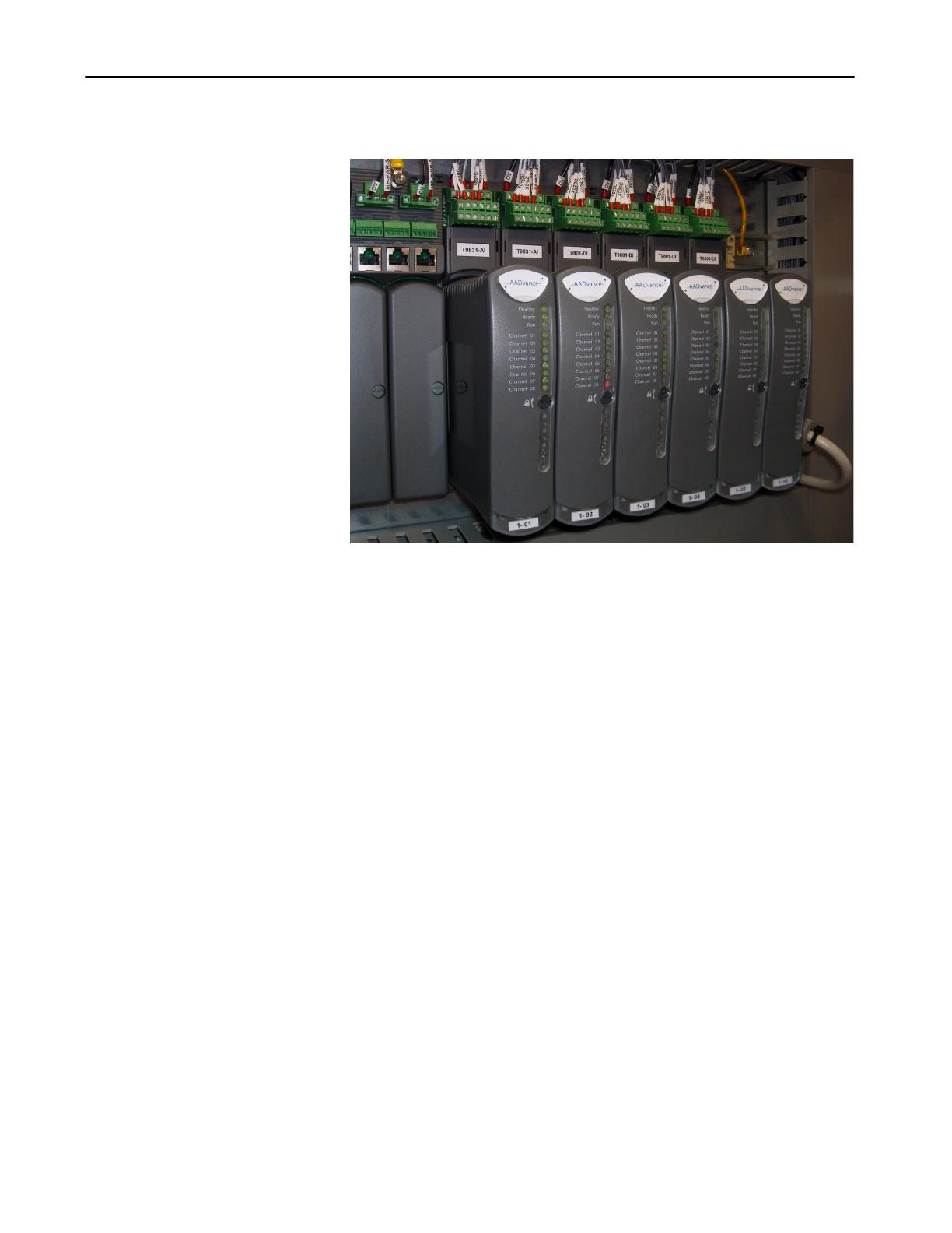
A controller is built from a range of compact plug-in modules that are
straightforward to assemble into a system. They can be mounted onto DIN
rails in a cabinet (see photograph) or directly mounted onto a wall in a control
room. They do not require forced air cooling or special environmental control
NOTE There is no provision for configuring triplicated output
modules
Rockwell Automation Publication ICSTT-RM446N-EN-P - April 2018 19
Introduction Chapter 1
equipment. However, certain consideration to the cabinet type must be applied
when used in hazardous environments.
A secure network communications protocol, developed by Rockwell
Automation for the AADvance system, permits distributed control and safety
using new or existing network infrastructure while ensuring the security and
integrity of the data. Individual sensors and actuators can connect to a local
controller, minimizing the lengths of dedicated field cabling. There is no need
for a large central equipment room; rather, the complete distributed system can
be administered from one or more PC workstations placed at convenient
locations.
The AADvance system has comprehensive built-in diagnostics, while
maintenance activities are straight forward operations which maximize system
availability.
The AADvance controller is developed and built for IEC 61131 compliance
and includes support for all five programming languages. Program access is
secured by a removable "Program Enable" key. Simulation software lets you
prove a new application before reprogramming and downloading, again
maximizing system uptime.

20 Rockwell Automation Publication ICSTT-RM446N-EN-P - April 2018
Chapter 1 Introduction
AADvance Features
The AADvance system controls complex and often critical processes in real
time — executing programs that accept external sensor signals, solving logic
equations, performing calculations for continuous process control and
generating external control signals. These user-defined application programs
monitor and control real-world processes in the oil and gas, refining, rail
transit, power generation and related industries across a wide range of control
and safety applications. AADvance products have a useful lifetime of 20 years.
The main features of the AADvance system are as follows:
• Facilitates differing fault tolerant topologies — 1 out of 1 with
diagnostics (1oo1D), 1 out of 2 with diagnostics (1oo2D) and 2 out of 3
with diagnostics (2oo3D)
• Flexible modular construction using individual modules to build a
system
• Operates as a stand-alone system or part of a larger distributed network
• Easily transformed from a simplex non-safety system to a fault tolerant
safety related system
• IEC 61508 certified
• Scalable I/O module expansion without system interruption
• Supports secure SIL 3 rated 'Black Channel' external communication
over Ethernet
• Supports industry standard protocols including MODBUS and HART
• Supports OPC when using an OPC Portal
System Security
An AADvance system, with its workstations and DCS interfaces, whether
using Ethernet networks or Serial links is likely part of a larger corporate
network which may expose the system to accidental or malicious infection,
attack or less obvious security vulnerabilities. If appropriate (or defined in the
SRS), a security risk assessment should be carried out and the appropriate level
of risk mitigation applied.
The following general security steps should be used to ensure the system is
secure:
• Network and workstation security must set up when installing and
setting up the system. As a minimum use the following security
measures:
• AADvance system must not be connected to a network with open
unsecured access to the Internet.
• A router firewall must be active on the Workstation, preventing access to
the unused Ethernet ports on each communication interface.
Page is loading ...
Page is loading ...
Page is loading ...
Page is loading ...
Page is loading ...
Page is loading ...
Page is loading ...
Page is loading ...
Page is loading ...
Page is loading ...
Page is loading ...
Page is loading ...
Page is loading ...
Page is loading ...
Page is loading ...
Page is loading ...
Page is loading ...
Page is loading ...
Page is loading ...
Page is loading ...
Page is loading ...
Page is loading ...
Page is loading ...
Page is loading ...
Page is loading ...
Page is loading ...
Page is loading ...
Page is loading ...
Page is loading ...
Page is loading ...
Page is loading ...
Page is loading ...
Page is loading ...
Page is loading ...
Page is loading ...
Page is loading ...
Page is loading ...
Page is loading ...
Page is loading ...
Page is loading ...
Page is loading ...
Page is loading ...
Page is loading ...
Page is loading ...
Page is loading ...
Page is loading ...
Page is loading ...
Page is loading ...
Page is loading ...
Page is loading ...
Page is loading ...
Page is loading ...
Page is loading ...
Page is loading ...
Page is loading ...
Page is loading ...
Page is loading ...
Page is loading ...
Page is loading ...
Page is loading ...
Page is loading ...
Page is loading ...
Page is loading ...
Page is loading ...
Page is loading ...
Page is loading ...
Page is loading ...
Page is loading ...
Page is loading ...
Page is loading ...
Page is loading ...
Page is loading ...
Page is loading ...
Page is loading ...
Page is loading ...
Page is loading ...
Page is loading ...
Page is loading ...
Page is loading ...
Page is loading ...
Page is loading ...
Page is loading ...
Page is loading ...
Page is loading ...
Page is loading ...
Page is loading ...
Page is loading ...
Page is loading ...
Page is loading ...
Page is loading ...
Page is loading ...
Page is loading ...
Page is loading ...
Page is loading ...
Page is loading ...
Page is loading ...
Page is loading ...
Page is loading ...
Page is loading ...
Page is loading ...
Page is loading ...
Page is loading ...
Page is loading ...
Page is loading ...
Page is loading ...
Page is loading ...
Page is loading ...
Page is loading ...
Page is loading ...
Page is loading ...
Page is loading ...
/


