Page is loading ...

1
Attention Contractors...
4000 Series
Installer’s Guide
A Step-by-Step Guide for Installing,
Operating and Maintaining a Complete
Lutron GRX-4000 Series System with
XP Series Switching Panels
LUTRON
XP

2
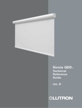
Overview
GRX-4000 Series Control Unit
GRAFIK Eye XP Series Panel
CLASS 2 TRANSFORMERS
PANEL
COVER
SWITCHING MODULE
CIRCUIT SELECTOR
N
N
LUTR
R
Link
Power (Pins
Data (Pins
Circ
Val
V
IE
V
AL
5
4
3
2
1
Load
Control and Zone
High End (optio
Circuit
Low End (optio
Using circuit
Using Zone
T
1
2
3
4 Non-
5 Elec.
Unassig
_
LUTR
12345
R
S
elec
C
ircui
S
elec
V
alu
S
elec
V
alu
D
isplay
H
H
TERMINAL BLOCKS

3
Troubleshooting Guide Page
Troubleshooting Guide.......................24,25
Directories
Circuit Directory ......................................26
Control Directory.....................................27
Maintenance
Maintenance ...........................................28
Glossary of Terms
Glossary of Terms...................................29
Look Inside a Panel Page
XP Series Panels..................................20
Control Wiring
Accessory to Control Unit to Panel .......21
Panel to Panel ......................................22
Circuit Selector
Circuit Selector Functions.....................23
Table of Contents
Install System Page
STEP 1: Mount Wallboxes ................................... 2
STEP 2: Mount Panels....................................... 2,3
STEP 3: Wire System.........................................4,5
STEP 4: Set Address Switches..............................6
STEP 5: Set Function Switches.............................7
STEP 6: Install Controls.........................................8
Start Up System
STEP 7: Activate Loads in Bypass........................8
STEP 8: Activate Controls.....................................9
STEP 9: Assign Load Types................................10
STEP 10: Address GRX-4000 Control Units......... 11
STEP 11: Remove Bypass Jumpers..................... 12
STEP 12: Check System....................................... 13
Set Up System Page
STEP 13: Assign Zones.........................................14
STEP 14: Set Up Scenes on the GRX-4000......... 15
STEP 15: Set Up Accessory Controls...............16,17
STEP 16: Set Normal/Emergency Switch............. 18
Reference Sheets
Step-by-Step Instructions
B
e
l
i
e
v
eit
o
r
n
o
t
,
t
h
i
s
i
s
s
u
p
p
o
s
e
d
t
o
l
o
o
k
l
i
k
e
a
d
i
c
t
i
o
n
a
r
y
!
T
h
i
s
i
c
on
w
a
s
c
r
e
a
t
e
d
b
y
B
r
e
n
t
M
.
N
y
e
,
J
u
l
y
6
,
1
9
9
5
.
B
e
l
i
e
v
eit
o
r
n
o
t
,
t
h
i
s
i
s
s
u
p
p
o
s
e
d
t
o
l
o
o
k
l
i
k
e
a
d
i
c
t
i
o
n
a
r
y
!
T
h
i
s
i
c
on
w
a
s
c
r
e
a
t
e
d
b
y
B
r
e
n
t
M
.
N
y
e
,
J
u
l
y
6
,
1
9
9
5
,
u
n
d
e
r
the
d
i
r
e
c
t
i
o
n
o
f
D
e
r
e
k
R
.
T
h
o
m
a
s
.
T
h
i
s
i
c
on
w
a
s
c
r
e
a
t
e
d
b
y
B
r
e
n
t
M
.
N
y
e
,
J
u
l
y
6
,
1
9
9
5
.
B
e
l
i
e
v
eit
o
r
n
o
t
,
t
h
i
s
i
s
s
u
p
p
o
s
e
d
t
o
l
o
o
k
l
i
k
e
a
d
i
c
t
i
o
n
a
r
y
!
T
h
i
s
i
c
on
w
a
s
c
r
e
a
t
e
d
b
y
B
r
e
n
t
M
.
N
y
e
,
J
u
l
y
6
,
1
9
9
5
.
B
e
l
i
e
v
eit
o
r
n
o
t
,
t
h
i
s
i
s
s
u
p
p
o
s
e
d
t
o
l
o
o
k
l
i
k
e
a
d
i
c
t
i
o
n
a
r
y
!
T
h
i
s
i
c
on
w
a
s
c
r
e
a
t
e
d
b
y
B
r
e
n
t
M
.
N
y
e
,
J
u
l
y
6
,
1
9
9
5
.
B
e
l
i
e
v
eit
o
r
n
o
t
,
t
h
i
s
i
s
s
u
p
p
o
s
e
d
t
o
l
o
o
k
l
i
k
e
a
d
i
c
t
i
o
n
a
r
y
!
T
h
i
s
i
c
on
w
a
s
c
r
e
a
t
e
d
b
y
B
r
e
n
t
M
.
N
y
e
,
J
u
l
y
6
,
1
9
9
5
.
u
n
d
e
r
the
d
i
r
e
c
t
i
o
n
o
f
D
e
r
e
k
R
.
T
h
o
m
a
s
.
T
h
i
s
i
c
on
w
a
s
c
r
e
a
t
e
d
b
y
B
r
e
n
t
M
.
N
y
e
,
J
u
l
y
6
,
1
9
9
5
.
B
e
l
i
e
v
eit
o
r
n
o
t
,
t
h
i
s
i
s
s
u
p
p
o
s
e
d
t
o
l
o
o
k
l
i
k
e
a
d
i
c
t
i
o
n
a
r
y
!
T
h
i
s
i
c
on
w
a
s
c
r
e
a
t
e
d
b
y
B
r
e
n
t
M
.
N
y
e
,
J
u
l
y
6
,
1
9
9
5
.
Table of Contents for GRAFIK Eye Switching Panel
XP

2
2-5/16" (6.7cm)
2-1/8"
Preferred feed and load
wire entry—may be
expanded to 2" max.
4-1/16" (10.3cm)
1"
Slot for recessed mounting
screws (8 places)
7/8" diameter knock out (44 places)
3/8"
1-5/8"
3/8"
.312 dia.
.624 dia.
Keyholes for
surface mounting
(4 places)
1"
2-1/4"
(5.7cm)
15-1/8" (38.4cm)
1/8"
2-5/16" (5.9cm)
1" (2.5cm)
Second preferred feed and
load wire entry—may be
extended to 2" max.
3/4"
41-3/4"
(106cm)
Left side may
be punched
Class 2 (SELV) only
control wiring entry
2"
1
2-1/4"
59"
(150cm)
No entrance on right
side except Class 2
knockouts
8" (20 cm)
2-7/16"
(6.2cm)
11" (28 cm)
Class 2 (SELV) only
alternate control
wiring entry
No entrance on all
x'd out knockouts
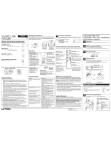
STEP 1: Mount Wallboxes
Use wallboxes with a minimum depth of 2-3/4"
(70mm) for Accessory Controls and 3-1/2" (89mm)
for GRX-4000 Series Control Units.
Multigang installations may require spacers between
wallboxes.
Mount wallboxes flush to 1/8" (3mm) below finished
wall surface.
Finished wall should not have gaps around the
wallbox of greater than 1/8" (3mm).
Mount Wallboxes and
Panels
STEP 2: Mount Panels
Top View
Front View
Bottom View
Control
GRX-CIR
GRX-4S-DW
GRX-AV‘s
GRX-4000 Series
Control Units
2 zone (2 gang)
3 zone (3 gang)
4 zone (4 gang)
6 zone (4 gang)
8 zone (4 gang)
All Others (1 gang)
Wallbox
Mounts in Ceiling with special mounting ring (provided)
Lutron # 241-399 (provided)
1900 Box (4"x4" junction box) or Lutron #241-496
Lutron # 241-519 3-1/2" (89mm) deep
(1 gang each, gangable)
or
2-3/4" (70mm), 3-1/2" (89mm) deep US Wallbox
Step by Step instructions for GRAFIK Eye Switching Panel
Left Side Right Side
WHEN SURFACE MOUNTING, THE KEYHOLE
ACCEPTS A MAXIMUM OF 1/4" MOUNTING
BOLT (1/4" IS RECOMMENDED)
WHEN FLUSH MOUNTING, MOUNT PANEL
FLUSH TO 1/8" (3MM) BELOW FINISHED WALL
SURFACE
XP Series
(Dimensions and Conduit Entry)
READ THE MAINTENANCE REFERENCE SHEET
BEFORE PAINTING THE PANEL OR COVER

3
N
N
LUTR
R
Link
Power (Pins
Data (Pins
Circ
Val
V
IE
V
AL
5
4
3
2
1
Load
Control and Zone
High End (optio
Circuit
Low End (optio
Using circuit
Using Zone
T
1
2
3
4 Non-
5 Elec.
Unassig
_
LUTR
12345
R
S
elec
C
ircui
S
elec
V
alu
S
elec
V
alu
D
isplay
H
H
N
N
LUTR
R
Link
Power (Pins
Data (Pins
Circ
Val
V
IE
V
AL
5
4
3
2
1
Load
Control and Zone
High End (optio
Circuit
Low End (optio
Using circuit
Using Zone
T
1
2
3
4 Non-
5 Elec.
Unassig
_
LUTR
12345
R
S
elec
C
ircui
S
elec
V
alu
S
elec
V
alu
D
isplay
H
H
Mount Wallboxes and
Panels
STEP 2: Mount Panels (cont.)
Suggested Surface Mount
Front View Side View Front View Side View
Suggested Recess Mount
CEILING
Notes:
• Keep length of raceway below 24" to avoid possible
derating (per NEC code for 10 or more conductors).
• Panel generates heat (see table at right). Mount
only where ambient temperature will be 0-40°C
(32°F-104°F).
• Reinforce wall structure as required for weight and
local codes.
• Panel clearances are 1-1/2" (38mm) to each side.
• Distribution Panel not included with XP Series Panel.
• Indoor Use Only. Type 1 enclosure.
• Relative Humidity < 90% non-condensing.
• XP Panels should be mounted within 7° of true
vertical.
CEILING
Weight w/o PackagingPanel
XP-24
XP-32
XP-48
Max BTU/Hrs.
For More Information...
Look inside an XP........................... 20
?
XP
ALTERNATE
FEED AND
LOAD CIRCUIT
WIRING
CLASS 2 (SELV)
WIRING TO
CONTROLS
WALL
FEED AND LOAD
CIRCUIT WIRING
Step by Step instructions for GRAFIK Eye Switching Panel
310
350
430
55 lbs (25 kg)
60 lbs (27 kg)
70 lbs (32 kg)
Caution - Internal relays will click while in
operation. Mount where audible noise is
acceptable.
Caution - Where and how the XP panel is
mounted may depend upon the wiring
method you choose (see step 3).
DISTRIBUTION
PANEL
ALTERNATE
FEED AND
LOAD CIRCUIT
WIRING
CLASS 2 (SELV)
WIRING TO
CONTROLS
WALL
FEED AND LOAD
CIRCUIT WIRING
DISTRIBUTION
PANEL

4
LUTRON
SEQUENCE
ZONE LOCK
SCENE LOCK
FADE OVERRIDE
LUTRON
SEQUENCE
ZONE LOCK
SCENE LOCK
FADE OVERRIDE
LUTRON
LUTRON
STEP 3: Wire System
GRX Wiring
2 #12 AWG (2.5mm
2
) FROM TERMINALS 1 TO 1, AND 2 TO 2
2 #18 AWG (1.0mm
2
) TWISTED SHIELDED PAIR FROM TERMINALS 3 TO 3, AND 4 TO 4 -
BELDEN #9461 OR ALPHA #2211 ARE #22 AWG AND ARE RECOMMENDED.
ALL 4 WIRES ARE AVAILABLE IN ONE CABLE FROM LIBERTY CABLE AT 1-800-530-8998.
LIBERTY P/N IS LUCOM-12/22-RBL
NOTE: TOTAL LENGTH OF WIRE MAY BE NO MORE THAN 2000 FEET FOR #12 AWG
(450m for 2.5mm
2
).
FOR PANEL TO PANEL WIRING, INCLUDE AN ADDITIONAL 1 #18 AWG (1.0mm
2
)
BETWEEN PANELS FROM TERMINALS 5 TO 5.
NOTE: WIRING LIMITATIONS INCLUDE
PANEL TO PANEL WIRING.
Wire System
For More Information...
Accessory Control to Control Unit Panel to Panel Wiring.................................22
to Panel Wiring.................................21
?
ACCESSORY
CONTROLS
(16 MAX.)
NTGRX-4S
NTGRX-4S-IR
GRX-CIR
GRX-4S-DW
NTGRX-RL
NTGRX-4Q
NTGRX-4PS
NTGRX-4M
GRX-AV
GRX-AV-SER
GRX-AV-RS232
GRX-AV-RS232/ATC
NTGRX-2B
GRX-4000 SERIES CONTROL UNITS
(8 MAX.)
GRX-4#02 (2 zone)
GRX-4#03 (3 zone)
GRX-4#04 (4 zone)
GRX-4#06 (6 zone)
GRX-4#08 (8 zone)
# = 1 for GRX-4100’s, 5 for GRX-4500’s
SSA CONTROLS
(10 MAX.)
NTGRX-1S
CLASS 2 WIRING
2 #18 AWG (1mm
2
) TO TERMINALS
SSA AND SSARET OF THE
INDIVIDUAL CONTROL UNIT TO HAVE
ITS SCENE 1 TOGGLED ON AND OFF.
• Maximum number of lighting control panels may
be increased using a repeater—contact Lutron.
• The following cables: Liberty #LUCOM-12/22-RBL,
Belden #9461, and Alpha #2211 are made with #22
AWG wire, and have been tested and approved.
Not all #22 AWG cable will work. Any #18 AWG
twisted, shielded pair will work.
Caution - Wire in a daisy-chain
arrangement as shown - no variations.
Do not substitute cables!
Notes:
• All control wiring is Class 2 (Extra Low Voltage).
Do not place any of these wires in with line voltage
(mains voltage) wiring.
• Panel may be placed in the middle of the wiring as
opposed to on the end as shown, but panel to
panel wiring may be more difficult.
• 2 #12 AWG (2.5mm
2
) wires will not fit in the
Accessory Control terminal blocks. Use the
diagram shown at right to make the connections
in the wallbox. #12 AWG (2.5mm
2
) is necessary
due to voltage drop on the wire.
• Shielding must be connected as shown, but do not
connect to Ground (Earth) or Accessory Control. It
is easiest to connect the bare drain wires and cut
off the outside shield.
• Make wire connections inside the wallbox, GP and
XP panel or in a junction box (provided by others)
within 8ft. (2.4m) from the terminals.
4
3
2
1
2 #12 AWG (2.5mm
2
)
1 #18 AWG
(1mm
2
)
-SHIELD/DRAIN
2 #12 AWG (2.5mm
2
)
Step by Step instructions for GRAFIK Eye Switching Panel
GRAFIK Eye GP, LP, or XP SERIES LIGHTING CONTROL PANELS
(Number of panels max = 33 - Number of Control Units -
Number of Accessory Controls)
CLASS 2 WIRING

Switched Hot
Load 16 A max
Neutral
Hot/Live In
Ground
H
SH
H
SH
H
SH
H
SH
H
SH
H
SH
H
SH
H
SH
Neutral
Dedicated Hot/Live
N
N
H
H
Wire System
STEP 3: Wire System (cont.)
Suggested wiring when panels are close together
Suggested wiring when panels are far apart
Notes:
• Terminal blocks accept one #14 AWG (2.5mm
2
)
through #10 AWG (4.0mm
2
) or two AWG #18 AWG
through #16 AWG wire.
• Two modules and the control feed are shown to the
left. The module terminal blocks are typical of the
rest of the possible 12 modules
• Lutron recommends that the Control Feed be a
dedicated circuit even though the control wiring
will draw 0.5 Amps max.
Danger - An XP Series panel is fed by
multiple circuits. Locate and lock each
feed in the OFF position.
Caution - XP Series panels require entry
of wires as specified. Improper entry will
block serviceable parts or violate NEC codes.
Warning - Do not remove bypass jumpers
at this step.
Caution - Lutron recommends the use of
a trough for ease of wiring (where space
permits).
Caution - Follow all local wiring codes.
5
Module wiring
Splice Neutrals
in Trough
Switched Hot/Live
Wire (SH)
SH
H
XP Panel
H
H
Load 16A Max.
N
SH
SH
N
Neutral
Wire (N)
Small
Distance
Hot/Live
Wire (H)
Distribution Panel
Load 16A Max.
N
SH
Neutral Wire (N)
Large
Distance
H
N
H
Switched Hot/Live
Wire (SH)
XP Panel
Reference Sheets for GRAFIK Eye Switching Panel
Hot/Live
Wire (H)
Distribution Panel

6
Address
N/A
Control 1
Control 2
Control 3
Control 4
Control 5
Control 6
Control 7
Control 8
Control 9
Control 10
Control 11
Control 12
Control 13
Control 14
Control 15
Control 16
STEP 4: Set Address Switches
Control
NTGRX-1S GRX-4000 Series
LUTRON
1
2
3
4
PARTITION STATUS
OPEN
CLOSED
NTGRX-RL NTGRX-4PS
SEQUENCE
ZONE LOCK
SCENE LOCK
FADE OVERRIDE
LUTRON
LUTRON
LUTRON
LUTRON
LUTRON
ALL OTHERS
Function
N/A
Leave switches as factory
set.
Go to Step 6 if no other
types of Accessory controls.
Setting Switches 5 and 6
requires system knowledge.
See Step 5 for function
options.
5 6
LUTRON
LUTRON
Action
No switches for addressing.
Go to Step 6 if no other types of
Accessory Controls.
Must set switches BEFORE
installing these controls.
Set Switches 1-4 on each
Accessory Control to a unique
address.
Must set switches BEFORE
installing these controls.
Set Switches 1-4 on each
Accessory Control to a unique
address.
Set Switches 5-6 to define the
function of control.
1 2 3 4 5 6
1 2 3 4
1 2 3 4 5 6
1 2 3 4 5 6
Set Address Switches
Notes:
• GRX-AV has 8 switch positions. Positions 7 and 8
also set the function.
• GRX-AV-RS232’s do not have an address—
follow instructions packaged with each control
and skip to step 6.
4
3
2
1
Back of Accessory Control
Switch
location
GRX-AV
Step by Step instructions for GRAFIK Eye Switching Panel
Factory Set
For More Information...
See also One-Line Diagram from submittals.
?
Caution - Do not install controls in
wallbox without setting the Address and
Function Switches.

7
NTGRX-4S,
GRX-4S-DW
NTGRX-4S-IR
w/GRX-IT,
GRX-CIR
w/GRX-IT
NTGRX-RL
NTGRX-4Q
NTGRX-4PS
NTGRX-4M
GRX-AV
NTGRX-1S
GRX-IT
GRX-8IT
NTGRX-2B
LUTRON
R
LUTRON
LUTRON
R
1 2 3 4 5 6
Set Function Switches
STEP 5: Set Function Switches
Factory Set
Activate Scenes 1-4
Not Applicable
Sequence Scenes 1-4
Not Applicable
Fifth button turns
Control Units On only.
Momentary Input
Activate Scenes 1-4
Momentary Input
Sequence Scenes 1-4
Momentary Input
4PS functions
Momentary Input
1 Channel fine tuning
Not Applicable
Not Applicable
Activate Scene 1 and
Off
Activate Scenes 5-8
Not Applicable
Not Applicable
Not Applicable
Not Applicable
Momentary Input
Activate Scenes 9-12
Momentary Input
Sequence Scenes 5-16
N/A
Momentary Input
NTGRX-4M Function
Not Applicable
Not Applicable
Activate Scenes 13
and 14
Activate Scenes 9-12
Not Applicable
Not Applicable
Not Applicable
Not Applicable
Momentary Input
Activate Scenes 5-8
Maintained Input
Sequence Scenes 1-4
Maintained Input
4PS functions
Maintained Input
Occupant Sensor
Scene 1 and Off
Not Applicable
Not Applicable
Single Partition
Function
LUTRON
LUTRON
1
2
3
4
PARTITION STATUS
OPEN
CLOSED
LUTRON
SEQUENCE
ZONE LOCK
SCENE LOCK
FADE OVERRIDE
Activate Scenes on
specified GRX-4000
Series Control Units
Raise/Lower specified
Zones on specified
GRX-4000 Series
Control Units
Affect specified GRX-
4000 Series Control
Units
Parallel specified GRX-
4000 Series Control
Units
Toggle 4 specified
groups of GRX-4000
Series Control Units On
and Off.
Affect specified GRX-
4000 Series Control
Units
Toggle between Scene 1
and Off of connected
GRX-4000 Series
Control Unit
Activate Scenes 1-4 or
1-8 and Off, and Raise/
Lower all zones of target
GRX-4000 Series
Control Unit
Affect specified GRX-
4000 Series Control
Units
5 6 5 6 5 6 5 6
Activate Scenes 13-16
Not Applicable
Sequence Scenes 5-16
Not Applicable
Fifth button turns
Control Units Off only.
Momentary Input
Activate Scenes 13-16
Maintained Input
Sequence Scenes 5-16
N/A
Maintained Input
Occupant Sensor
Off Only
Not Applicable
Not Applicable
Activate Scene 16 w/
lockout or previous
Scene w/o lockout
GRX-AV
7 8
7 8
Function Set by Switches
on Back of Control
1 2 3 4 5 6
Function Set
with Front
Buttons
(See Step 17)
Accessory Control
Step by Step instructions for GRAFIK Eye Switching Panel
LUTRON
LUTRON
LUTRON
R
Factory Set
Factory Settings

8
Faceplate
Adapter
Control Facepla
Adapter M
Screws
Control Mounting
Screws
Wallbox
Control
Link
Install Controls and
Activate Loads
STEP 6: Install Controls
After completing steps 4 and 5, mount controls.
Refer to detailed mounting instructions packaged with
each control.
STEP 7: Activate Loads in Bypass
A. Check that the bypass jumpers are in place.
These jumpers protect the switch mechanism from
wiring faults and must be used to check load wiring
when it is installed or modified.
B. Complete load wiring.
C. Turn a load’s input circuit breaker ON.
The loads should energize, the feed breaker should
not trip, and total load current must be no more
than 16 Amps.
D. Repeat ‘C.’ for each circuit with completed load
wiring.
Warning - DO NOT remove bypass
jumpers at this time.
Step by Step instructions for GRAFIK Eye Switching Panel
WALLBOX
CONTROL
CONTROL
MOUNTING SCREWS
ADAPTER
MOUNTING SCREWS
FACEPLATE
ADAPTER
FACEPLATE
CONTROL
LINK
2 position
Bypass
Jumper
LUTRO
R
Link
Power (Pins
Data (Pins
Circui
Valu
V
IE
V
ALU
5
4
3
2
1
Load
Control and Zone
High End (optional
Circuit
Low End (optional
Using circuit
Using Zone
T
1 Inc/Mag
2
3
4 Non-
5 Elec.
Unassigne
_
LUTRO
12345
R
S
elect
C
ircuit
S
elect
V
alue
S
elect
V
alue
D
isplayed
N
N
H
H

9
For More Information...
Troubleshooting Guide.................24, 25
STEP 8: Activate Controls
Once all controls are installed and wiring verified, turn
the control wiring feed circuit breaker ON.
Check that the Power OK LED at the top of the
Circuit Selector is ON. If the Power OK LED is
off, turn off the control breaker, check for shorts
between wires 1 and 2, or 2 and ground.
Note:
For multiple panels once one Power OK LED is
ON, all the Power OK LED’s in all system Circuit
Selector’s should turn ON.
Push scene buttons on Accessory Controls. All GRX-
4000 Series Control Units and Accessory Controls
should act in parallel (e.g. pressing scene 1 on a
control will select scene 1 on all controls, pressing a
raise button will raise all zones).
Notes:
• NTGRX-4Q, NTGRX-4PS, NTGRX-4M
and GRX-AV-RS232’s will be inactive until
Control Set Up is completed.
• GRX-AV will be active only if set to affect Scenes
1-4 and OFF (switches 5,6,7, and 8 all UP).
• NTGRX-2B will be active only if set to affect Scene
1 and OFF (switches 5 and 6 both UP).
• Check for miswires if the controls do not act as
described.
SM
LUTRON
FADE OVERRIDE
ZONE
MASTER
ZONE 6ZONE 5ZONE 4ZONE 3ZONE 2ZONE 1
Push
GRX-4000 Series Control Unit
(6 zone unit shown)
Accessory Control
(NTGRX-4S shown)
LUTRON
Push
Activate Controls
?
‘Power OK’ LED
Step by Step instructions for GRAFIK Eye Switching Panel
S
ELECT
V
ALUE
D
ISPLAYED
Load Type
Circuit
Control and Zone Assigned
Using circuit schedule
Value
3
4
5
1 Inc/Mag LV
2 Fluorescent
3 Neon/CC
S
ELECT
V
ALUE
V
IEW
V
ALUE
4 Non-dim
5 Elec. LV
– Unassigned
S
ELECT
C
IRCUIT
Link Status
Using Zone Capture
Low End Trim (optional)
High End Trim (optional)
Circuit Level
TM
®
Power OK (Pins 1,2)
Data OK (Pins 3,4)
2
1

10
S
ELECT
V
ALUE
D
ISPLAYED
Load Type
Circuit
Control and Zone Assigned
Using circuit schedule
Value
3
4
5
1 Inc/Mag LV
2 Fluorescent
3 Neon/CC
S
ELECT
V
ALUE
V
IEW
V
ALUE
4 Non-dim
5 Elec. LV
– Unassigned
S
ELECT
C
IRCUIT
Link Status
Using Zone Capture
Low End Trim (optional)
High End Trim (optional)
Circuit Level
TM
®
Power OK (Pins 1,2)
Data OK (Pins 3,4)
2
1
To change Load Types:
A. Press and hold buttons 1 and 5 until
LED lights.
B. Press button 5 repeatedly until Load Type lights.
C.Tap button 2 so that ‘AC’ (All Circuits) appears in
the Circuit display.
D.Press button 3 repeatedly (press button once per
second since updating is slower in all circuits) until
‘4’ appears in the Value display.
E. Press and hold buttons 1 and 5 until
VIEW VALUE LED lights.
Notes:
• Most applications will use Load Type 4. Use Load
Type 6 for circuits controlling screens.
• The Circuit Selector Display will go out automatically
after 20 minutes of the last button press.
• Mark all changes to the Circuit Selector’s Values on
the Circuit Directory for future reference.
S
ELECT
V
ALUE
D
ISPLAYED
Load Type
Circuit
Control and Zone Assigned
Using circuit schedule
Value
3
4
5
1 Inc/Mag LV
2 Fluorescent
3 Neon/CC
S
ELECT
V
ALUE
V
IEW
V
ALUE
4 Non-dim
5 Elec. LV
– Unassigned
S
ELECT
C
IRCUIT
Link Status
Using Zone Capture
Low End Trim (optional)
High End Trim (optional)
Circuit Level
TM
®
Power OK (Pins 1,2)
Data OK (Pins 3,4)
2
1
STEP 9: Assign Load Types
Assigning Load Types is done using the Circuit
Selector located in each XP Series panel.
Press button 5 repeatedly until Load Type lights.
Use buttons 1 and 2 to view present load type of each
circuit. Note that ‘ - ’ in the Value display means a
Load Type is not assigned to the circuit.
If load types are already assigned, compare them to
the Circuit Directory (if provided).
If there are no changes to be made, skip to Step 10.
Circuit Selector
Assign Load Types
A,F
SELECT VALUE
Step by Step instructions for GRAFIK Eye Switching Panel
44
44
4
For More Information...
Circuit Selector Functions.................23
Circuit Directory.................................26
?

11
S
ELECT
V
ALUE
D
ISPLAYED
Load Type
Circuit
Control and Zone Assigned
Using circuit schedule
Value
3
4
5
1 Inc/Mag LV
2 Fluorescent
3 Neon/CC
S
ELECT
V
ALUE
V
IEW
V
ALUE
4 Non-dim
5 Elec. LV
– Unassigned
S
ELECT
C
IRCUIT
Link Status
Using Zone Capture
Low End Trim (optional)
High End Trim (optional)
Circuit Level
TM
®
Power OK (Pins 1,2)
Data OK (Pins 3,4)
2
1
STEP 10: Address GRX-4000 Control
Units
Push the scene 1 button on a GRX-4000 Series
Control Unit. The scene 1 LED should go on.
Address Control Unit as follows:
A. Push and hold top and bottom scene buttons until
scene LEDs begin to cycle.
B. Push FADE button until ‘A-’ is displayed in the
FADE window. If A1 through A8 appears, then go
to D since the Control Unit is already addressed.
C.Push MASTER button once. The control will
automatically choose the next available address.
Note the address of each on the Control Directory
(A1-A8).
If a Control or Load Directory already exists, push
MASTER and buttons to have the address
match these directories.
D.Push and hold the top and bottom buttons until the
scene LEDs stop cycling.
Repeat Steps A-D on all GRX-4000 Series Control
Units.
SM
LUTRON
FADE OVERRIDE
ZONE
MASTER
ZONE 6ZONE 5ZONE 4ZONE 3ZONE 2ZONE 1
A,D
B
C
GRX-4000 Series Control Unit
For More Information...
Troubleshooting Guide.................24, 25
Control Directory...............................27
?
Address GRX-4000
Control Units
As soon as a GRX-4000 Series Control Unit is
addressed, check that the Data OK LED (located
below the Power OK LED on the Circuit Selector)
begins to blink. Blinking indicates that the wiring from
a GRX-4000 Series Control Unit to the panel is
correct.
Note:
As soon as a GRX-4000 Series Control Unit is
addressed, Accessory Controls will no longer have
any affect on the GRX-4000 Series Control Units.
The Accessory Controls will be reactivated in
Step 16.
Not lit before addressing
Blinking after
addressing
(approximately once per
second)
Step by Step instructions for GRAFIK Eye Switching Panel

12
Remove Bypass
Jumpers
STEP 11: Remove Bypass Jumpers
Repeat Step 7 if load wiring has been modified.
Turn circuit breakers OFF.
Danger - Do not remove or replace
bypass jumpers while power is ON.
Loosen both screws of each bypass jumper.
Remove and store the bypass jumpers for possible
later use.
Store the bypass jumpers at the bottom of the panel.
DO NOT place them on top of the module.
Warning - When working on any load
(such as replacing a bulb), turn Off
power to the module that powers the
load. Turn the module power off by
switching its input circuit breaker
(MCB) Off.
Turning ON to a load fault WILL
irreparably damage the switch module.
Damage caused by short circuits and
miswiring is not covered in the product
warranty.
Turn Circuit Breakers ON.
BYPASS JUMPERS—
Replace whenever a load
is serviced.
Step by Step instructions for GRAFIK Eye Switching Panel
H
SH
H
SH
H
SH
H
SH
H
SH
H
SH
H
SH
H
SH
Terminal blocks
for 2 modules

13
For More Information...
Circuit Directory.................................26
Control Directory...............................27
?
Check System
STEP 12: Check System
Until zones are assigned in Step 13, all circuits will be
controlled by the first zone of the GRX-4000 Series
Control Unit addressed to ‘A1’. Locate zone 1 of this
‘A1’ control (referred to as A1 1 in the Circuit Selector)
and use it to check that all circuits turn ON and OFF
as expected.
(This address was set in Step 10.)
Note:
If the system has already been Set Up, scenes will
work and A1 1 will not control all circuits.
SM
LUTRON
FADE OVERRIDE
ZONE
MASTER
ZONE 6ZONE 5ZONE 4ZONE 3ZONE 2ZONE 1
First zone of GRX-4000 Series
Control Unit addressed ‘A1’
Step by Step instructions for GRAFIK Eye Switching Panel
To assure proper Set Up, you must have
one or more of the following:
• Factory Customized Set Up.
• Knowledge of how the system is
to operate.
• Plans and specifications from owner’s
representative on how the system is to
be set-up.
• Owner or owner’s representative
STOP!
Possible questions:
•
What should each scene be used for?
Examples include - Day lighting, Night lighting,
Meeting, Accenting, etc...
•
Which circuits should be on in each scene?

14
S
ELECT
V
ALUE
D
ISPLAYED
Load Type
Circuit
Control and Zone Assigned
Using circuit schedule
Value
3
4
5
1 Inc/Mag LV
2 Fluorescent
3 Neon/CC
S
ELECT
V
ALUE
V
IEW
V
ALUE
4 Non-dim
5 Elec. LV
– Unassigned
S
ELECT
C
IRCUIT
Link Status
Using Zone Capture
Low End Trim (optional)
High End Trim (optional)
Circuit Level
TM
®
Power OK (Pins 1,2)
Data OK (Pins 3,4)
2
1
S
ELECT
V
ALUE
D
ISPLAYED
Load Type
Circuit
Control and Zone Assigned
Using circuit schedule
Value
3
4
5
1 Inc/Mag LV
2 Fluorescent
3 Neon/CC
S
ELECT
V
ALUE
V
IEW
V
ALUE
4 Non-dim
5 Elec. LV
– Unassigned
S
ELECT
C
IRCUIT
Link Status
Using Zone Capture
Low End Trim (optional)
High End Trim (optional)
Circuit Level
TM
®
Power OK (Pins 1,2)
Data OK (Pins 3,4)
2
1
Assign Zones
STEP 13: Assign Zones
A. Press and hold buttons 1 and 5 until
lights.
B. Press button 5 repeatedly until
Using Circuit Schedule lights.
C.Use buttons 3 and 4 to assign control (factory set
to A1) and zone (factory set to 1) for each circuit.
Whichever item is blinking can be changed. See
the Control Schedule for control locations. If zones
are already assigned, skip to Step 15.
Example - If the control desired is addressed to
‘A2’ and the zone desired is the 3rd from the left,
use buttons 3 and 4 to get ‘A23’ as a value for the
appropriate circuit.
D.Use buttons 1 and 2 to change to the next circuit
and then repeat Step C. Do this for all affected
circuits. Record each circuit’s control and zone on
the Circuit Directory.
E. Press and hold buttons 1 and 5 until
VIEW VALUE lights. The Circuit Selector’s
display will go out automatically after 20 minutes
of the last button push.
Notes:
• More than one circuit can be assigned to the
same zone.
•
Zone Capture TM
is an alternate method for
assigning zones. It is described in the Circuit
Selector Functions Reference Sheet.
A,E
SELECT VALUE
Step by Step instructions for GRAFIK Eye Switching Panel
For More Information...
Circuit Selector Functions.................23
Circuit Directory.................................26
Control Directory...............................27
?

15
SM
LUTRON
FADE OVERRIDE
ZONE
MASTER
ZONE 6ZONE 5ZONE 4ZONE 3ZONE 2ZONE 1
STEP 14: Set Up Scenes on the GRX-4000
A. Lift the cover flap on a GRX-4000 Series Control
Unit (flap hinges up).
B. Press the Scene 1 button.
C.Press and buttons of each zone to create a
scene. As soon as a zone is changed, the GRX-
4000 Series Control Unit will remember it.
D.Adjust the fade time using and FADE
buttons.
Note:
The fade time can be adjusted from 0 to 59
seconds or 1 to 60 minutes.
E. Press Scene 2 and repeat C-D. Do this for all
scenes.
Note:
Off scene may have Fade time adjusted.
F. Repeat Steps A-E for all of the GRX-4000 Series
Control Units on the job.
A
E
DC
GRX-4000 Series Control Unit
Set Up Scenes on the
GRX-4000
B
Step by Step instructions for GRAFIK Eye Switching Panel

16
Control
(only 1 at a time)
GRX-4000
Series Control
Unit
NTGRX-4S
NTGRX-4Q
NTGRX-4S-IR
GRX-CIR
w/GRX-IT
GRX-4S-DW
NTGRX-RL
NTGRX-4PS
NTGRX-4M
GRX-AV
NTGRX-2B
as a Scene
Selector
NTGRX-2B
as a
Partition
Switch
STEP 15: Set Up Accessory Controls
All Accessory Controls (except NTGRX-1S) must be
set up to make a Control Unit(s) “listen” to button
presses on the Accessory Control.
• Only one Accessory Control can be set up at one
time.
• A Control Unit can also be made to “listen” to
another Control Unit and is therefore listed with the
Accessory Controls at right.
Follow Steps A-C for each Accessory Control.
Notes:
• Accessory Controls can not be made to “listen” to
each other , but a GRX-4000 Series Control Unit
can be made to “listen” to more than one
Accessory Control.
• When it is desired for two GRX-4000 Series
Control Units to always respond to each other’s
button presses, the first Control Unit must be set up
to respond to the second Control Unit’s buttons,
and then the second Control Unit must be set up to
respond to the first Control Unit’s buttons.
• An NTGRX-1S is wired directly to the GRX-4000
Series Control Unit that is to “listen” to it. No set-up
is required.
• GRX-AV-RS232’s do not follow this chart. See
instructions packaged with each control.
Set Up Accessory
Controls
STEP A: Place Control to ‘Talk’ in Set-Up Mode
Action
Press and hold first and fifth buttons of a Control
Unit.
Press and hold first and fifth buttons on Accessory
Control until its LEDs cycle sequentially.
Note: GRX-CIR only has 1 LED. Use the GRX-IT
to activate the first and fifth buttons.
Press and hold Raise and Lower buttons of
NTGRX-RL until its LED blinks (LED is located
behind faceplate)
Press and hold first and fifth buttons of the
NTGRX-4PS until LED 1 blinks.
Press and hold first and fifth buttons of the
NTGRX-4M until LED 1 blinks.
Press and hold the Program Switch until its LEDs
react like the simulated Accessory.
Press and hold both buttons of the NTGRX-2B until
its LED blinks (LED is located behind faceplate).
LUTRON
LUTRON
SEQUENCE
ZONE LOCK
SCENE LOCK
FADE OVERRIDE
LUTRON
1 2 3 4 5 6
LUTRON
1
2
3
4
PARTITION STATUS
OPEN
CLOSED
LUTRON
R
LUTRON
LUTRON
LUTRON
GRX-AV

17
Step by Step instructions for GRAFIK Eye Switching Panel
STEP 15: Set Up Accessory Controls (cont.)
Set Up Accessory
Controls
STEP B: Make Control Unit “Listen” STEP C: Take Control Out of Set-Up Mode
Control
(only 1 at a time)
GRX-4000
Series Control
Unit
NTGRX-4S
NTGRX-4Q
NTGRX-4S-IR
GRX-CIR
w/GRX-IT
GRX-4S-DW
NTGRX-RL
NTGRX-4PS
NTGRX-4M
GRX-AV
NTGRX-2B
as a Scene
Selector
NTGRX-2B
as a
Partition
Switch
Action
Press and hold another Control Unit’s Scene 1
button until its LEDs blink in unison. (To make it
stop “listening”, hold OFF button until LEDs go dark.
Press and hold Scene 1 on a Control Unit until its
LEDs blink in unison. (To make it stop “listening”,
hold OFF button until LEDs go dark.)
Press button of GRX-4000 Control Unit on
all zones that are to be affected by the NTGRX-RL
(to remove, press button).
Choose two Control Units on either side of a
Partition. Press and hold Scene 1 on a Control
Unit until its LEDs blink in unison. Repeat Scene 1
hold on the other Control Unit. Press the next
button on the NTGRX-4PS. Choose another pair
of Control Units. Repeat Scene 1 hold procedure
for each of the NTGRX-4PS buttons. (To remove,
hold OFF button on each Control Unit until LEDs
go dark.)
Choose a Control Unit to be toggled by the
NTGRX-4M. Press and hold Scene 1 on the
Control Unit until its LEDs blink in unison. Repeat
Scene 1 hold on other Control Units to be toggled.
Press the next button on the NTGRX-4M. Choose
a Control Unit to be toggled. Repeat Scene 1 hold
procedure for all 5 of the NTGRX-4M buttons.
Button 5 only turns ON or OFF (it does not toggle).
(To remove, hold OFF button on the Control Unit
until its LEDs go dark).
See above instructions for the simulated
Accessory Control.
Press and hold Scene 1 on a Control Unit until its
LEDs blink in unison. (To remove, hold OFF button
until LEDs go dark).
Press and hold Scene 1 on a Control Unit until its
LEDs blink in unison. Repeat Scene 1 hold
procedure for the other Control Units to be affected.
(To remove, hold OFF button until LEDs go dark)
LUTRON
Control
(only 1 at a time)
GRX-4000
Series Control
Unit
NTGRX-4S
NTGRX-4Q
NTGRX-4S-IR
GRX-CIR
w/GRX-IT
GRX-4S-DW
NTGRX-RL
NTGRX-4PS
NTGRX-4M
GRX-AV
NTGRX-2B
as a Scene
Selector
NTGRX-2B
as a
Partition
Switch
Action
Press and hold first and fifth buttons of the original
GRX-4000 Series Control Unit until LEDs stop
sequencing.
Press and hold first and fifth buttons on Accessory
Control until all LEDs stop cycling.
Press and hold Raise and Lower buttons on
NTGRX-RL until its LED stops blinking.
Press and hold first and fifth buttons of the
NTGRX-4PS until all LEDs stop blinking.
Press and hold first and fifth buttons of the
NTGRX-4M until all LEDs stop blinking.
If the GRX-AV’s LEDs are sequencing, press and
hold the Program Switch until the LEDs stop
sequencing. If the GRX-AV has 1 LED blinking,
press the program switch repeatedly until there are
no blinking LEDs.
Press and hold both buttons of the NTGRX-2B
until the LED stops blinking.
LUTRON
LUTRON
SEQUENCE
ZONE LOCK
SCENE LOCK
FADE OVERRIDE
LUTRON
1 2 3 4 5 6
LUTRON
1
2
3
4
PARTITION STATUS
OPEN
CLOSED
LUTRON
R
LUTRON
LUTRON
SEQUENCE
ZONE LOCK
SCENE LOCK
FADE OVERRIDE
LUTRON
1 2 3 4 5 6
LUTRON
1
2
3
4
PARTITION STATUS
OPEN
CLOSED
LUTRON
R
LUTRON
LUTRON
LUTRON
GRX-AV
LUTRON
LUTRON
GRX-AV
STEP D: Repeat Steps A-C for All Accessory Controls

18
Circuit Selector in
Normal (Non-Essential)
Panel
Circuit Selector in
Emergency (Essential)
Lighting Panel
SW6 SW6
Move left Move right
SELECT VALUE DISPLAYED
Load Type
Circuit
Control and Zone Assigned
Using circuit schedule
Value
3
4
5
1 Inc/Mag LV
2 Fluorescent
3 Neon/CC
SELECT VALUE
VIEW VALUE
4 Non-dim
5 Elec. LV
– Unassigned
SELECT CIRCUIT
Link Status
Using Zone Capture
Low End Trim (optional)
High End Trim (optional)
Circuit Level
TM
®
Power OK (Pins 1,2)
Data OK (Pins 3,4)
2
1
Set Normal/Emergency
Switch
SELECT VALUE DISPLAYED
Load Type
Circuit
Control and Zone Assigned
Using circuit schedule
Value
3
4
5
1 Inc/Mag LV
2 Fluorescent
3 Neon/CC
SELECT VALUE
VIEW VALUE
4 Non-dim
5 Elec. LV
– Unassigned
SELECT CIRCUIT
Link Status
Using Zone Capture
Low End Trim (optional)
High End Trim (optional)
Circuit Level
TM
®
Power OK (Pins 1,2)
Data OK (Pins 3,4)
2
1
STEP 16: Set Normal/Emergency Switch
(Non-Essential/Essential)
Note:
This step is only performed if there are any panels
with Emergency (Essential) Lighting Circuits on
the job.
Panels are shipped with Switch 6 (located at the base
of each Circuit Selector) in the center position for
operation without any Emergency (Essential) Lighting
Circuits.
Identify a panel supplied with Normal (Non-Essential)
power. Move its Switch 6 to the left position.
For all the Emergency (Essential) Lighting Panels,
move switch 6 to the right position.
In this arrangement, the Emergency (Essential)
Lighting Panel will “sense” the Normal (Non-Essential)
Panel’s power. When Normal (Non-Essential) power
is removed, the Emergency (Essential) Lighting will
go to ‘ord’ override levels (factory set to ON).
Loss of Normal (Non-Essential) power can be
simulated by turning off all connected Normal (Non-
Essential) Panels’ Control Breakers.
When Switch 6 is left in its center position (as
shipped), terminal 5 has no affect on the Circuit
Selector operation.
Notes:
• If there is no Normal Panel, contact Lutron
for GRAFIK Eye 4000 Application Note #5:
How to
create a ‘sense’ line.
• Override (‘ord’) Level is factory set to turn all circuits
ON. If the override level is to be OFF, contact Lutron
for GP Panel Advanced Function #1.
/