Page is loading ...

GRX-LC8 CONTROLLER
Installation and Setup Instructions Please Read
DESCRIPTION
The GRX-LC8 controller works with a GRX-CES series daylight sensor to allow for changes to be made to a Lutron
lighting system through a contact closure. It is a single channel lighting controller that features an adjustable ON
setpoint as well as an adjustable OFF setpoint. The controller features a signal deadband and time delay to ensure
lighting stability. The controller is powered by a PP series power pack.
INSTALLATION
Mount the controller using the adhesive strips provided. Choose a location where the PP series power pack can be
provided with power.
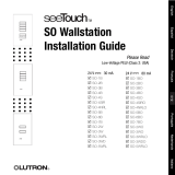
WIRING
R
6 7 8
1 2 3 4 5
SENSOR DELAY
OFF
ON
On LED
Off LED
On Setting Knob
Off Setting Knob
Sensor (typical)
Power pack
PP-120H,
PP-277H, or
PP-UNVH*
LC8 Controller
Yellow (0-10 V signal)
Black
(common)
Red (24 V )
Red (24 V )
Black
Blue (cap off)
Black (120 V )
White (neutral)
Red (cap off)
Red (cap off)
N.O. contact
Common
N.C. contact
To Lutron lighting control system
PELV (Class 2: USA) only
No line voltage
Notes
• When interfacing to a Lutron system, the
N.C. contact will turn lights on (contact
closure close) when daylight levels are
low, and turn lights off (contact closure
open) when daylight levels are high.
• When the Off or On LED is lit, the light
level is above the setting of its respective
knob.
CALIBRATION
Each GRX-CES sensor is calibrated during manufacturing to the light levels in its intended environment (indoor,
outdoor, etc.). Below is a chart of the settings for each model. The first column corresponds to the settings on the
adjustment knobs in the GRX-LC8 controller.
Adjustment
Knob Setting
Corresponding Foot-Candle Thresholds
GRX-CESI GRX-CESA GRX-CESS GRX-CESO
Below 1 0 2 10 0
1 10 100 200 25
2 20 200 400 50
3 30 300 600 75
4 40 400 800 100
5 50 500 1000 125
6 60 600 1200 150
7 70 700 1400 175
8 80 800 1600 200
9 90 900 1800 225
10 100 1000 2000 250
*Check with Lutron for availability

LIMITED WARRANTY
Lutron will, at its option, repair or replace any unit that is defective in materials or manufacture within one year after
purchase. For warranty service, return unit to place of purchase or mail to Lutron at 7200 Suter Rd., Coopersburg,
PA 18036-1299, postage pre-paid.
This warranty is in lieu of all other express warranties, and the implied warranty of merchantability is limited to
one year from purchase. This warranty does not cover the cost of installation, removal or reinstallation, or dam-
age resulting from misuse, abuse, or improper or incorrect repair, or damage from improper wiring or installation.
This warranty does not cover incidental or consequential damages. Lutron’s liability on any claim for damages
arising out of or in connection with the manufacture, sale, installation, delivery, or use of the unit shall never
exceed the purchase price of the unit.
This warranty gives you specific legal rights, and you may also have other rights which vary from state to state. Some
states do not allow limitations on how long an implied warranty lasts, so the above limitation may not apply to you.
Some states do not allow the exclusion or limitation of incidental or consequential damages, so the above limitation
or exclusion may not apply to you.
Lutron and the sunburst logo are registered trademarks of Lutron Electronics Co., Inc. © 2009.
World Headquarters
Lutron Electronics Co., Inc.
7200 Suter Road
Coopersburg, PA 18036
TEL +1-610-282-3800
FAX +1-610-282-1243
Internet: www.lutron.com
E-mail: [email protected]
Lutron Electronics Co., Inc.
Made and printed in U.S.A.
P/N 031-290 Rev. A 08.04.09
R
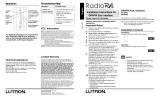
CALIBRATION (CONTINUED)
Using the chart on the previous page, set the On adjustment knob: This is the low light level that will trigger your
lights to go on. Set the Off adjustment knob: This is the high light level that will trigger your lights to turn off. For
proper operation, set the On knob at least 10% (1 tick mark on the knob) lower than the Off knob to create the
dead band.
TROUBLESHOOTING
If your system is not functioning, check for the following problems:
• Check the controller power: On the GRX-LC8 controller, you should be able to measure 24 V between terminals
4 and 5.
• Check the sensor power: Connect a voltmeter between its yellow and black wires. When the sensor is covered, it
should produce 0 V , and when it is in bright light, it should produce 10 V . If this is not the case, replace the
sensor.
• Check the controller function: The input delay switch should be off (up). With no sensor connected, all three LEDs
should be lit; when you short terminals 1 and 2 together, the LEDs should turn off. If this is not the case, replace
the controller.
• Check the controller settings: On the GRX-LC8 controller, the adjustment knob settings may be faulty. Follow the
above calibration instructions to reset.
1
2
3
4
5
6
7
8
9
10
1
2
3
4
5
6
7
8
9
10
SIMULATOR
JACK
INPUT
TIME
DELAY
RELAY
STATUS
ON
ON
ON
OFF
OFF
OFF
FOR FURTHER
CALIBRATION
INFORMATION,
SEE IMM
(INSTALLATION
MAINTENANCE
MANUAL).
OCC
SENSOR
FOOTCANDLE
SETTINGS
1 10
10 100
25 250
100 1000
200 2000
I
O
A
S
OFF setting
ON setting
Daylighting Level (foot-candles)
Dead
band
Time of day
Time of day
Lights ON Lights ON
Lights OFF
GRX-LC8
Calibration
/