EPSILON
SYNCHRONIZATION
SUPPLY
UNIT(SSU)
INSTALLATION, OPERATING AND USER’S MANUAL
95 Methodist Hill Drive
Rochester, NY 14623
Phone: US +1.585.321.5800
Fax: US +1.585.321.5219
3 Avenue du Canada
91974 Les Ulis, France
Phone: +33(0)1.64.53.39.80
Fax: +33(0)1.64.53.39.81
www.spectracomcorp.com
www.spectracom.fr
Ref. Number 08921-D0
Manual Revision D0
30 July 2008

Copyright © 2008 Spectracom Corporation. The contents of this publication may not be
reproduced in any form without the written permission of Spectracom Corporation.
Specifications subject to change or improvement without notice.
Spectracom, EPSILON CLOCK, NetClock, Ageless, TimeGuard, TimeBurst, TimeTap,
LineTap, MultiTap, VersaTap, and Legally Traceable Time are Spectracom registered
trademarks. All other products are identified by trademarks of their respective
companies or organizations. All rights reserved.

SPECTRACOM LIMITED WARRANTY
LIMITED WARRANTY
Spectracom warrants each new product manufactured and
sold by it to be free from defects in software, material,
workmanship, and construction, except for batteries, fuses, or
other material normally consumed in operation that may be
contained therein AND AS NOTED BELOW, for five years after
shipment to the original purchaser (which period is referred to
as the “warranty period”). This warranty shall not apply if the
product is used contrary to the instructions in its manual or is
otherwise subjected to misuse, abnormal operations, accident,
lightning or transient surge, repairs or modifications not
performed by Spectracom.
The GPS receiver is warranted for one year from date of
shipment and subject to the exceptions listed above. The
power adapter, if supplied, is warranted for one year from date
of shipment and subject to the exceptions listed above.
THE TIMEVIEW ANALOG CLOCKS ARE WARRANTED FOR
ONE YEAR FROM DATE OF SHIPMENT AND SUBJECT TO
THE EXCEPTIONS LISTED ABOVE.
THE TIMECODE READER/GENERATORS ARE
WARRANTED FOR ONE YEAR FROM DATE OF SHIPMENT
AND SUBJECT TO THE EXCEPTIONS LISTED ABOVE.
THE WIRELESS CLOCK SYSTEM TRANSMITTERS AND/OR
TRANSCEIVERS AND CLOCKS ARE WARRANTED FOR
TWO YEARS FROM DATE OF SHIPMENT AND SUBJECT
TO THE EXCEPTIONS LISTED ABOVE.
THE EPSILON CLOCKS, BOARDS, AND
SYNCHRONIZATION UNITS ARE WARRANTED FOR TWO
YEARS FROM DATE OF SHIPMENT AND SUBJECT TO THE
EXCEPTIONS LISTED ABOVE.
The Rubidium oscillator, if supplied, is warranted for two years
from date of shipment and subject to the exceptions listed
above.
All other items and pieces of equipment not specified above,
including the antenna unit, antenna surge suppressor and
antenna pre-amplifier are warranted for 5 years, subject to the
exceptions listed above.
WARRANTY CLAIMS
Spectracom’s obligation under this warranty is limited to in-
factory service and repair, at Spectracom’s option, of the
product or the component thereof, which is found to be
defective. If in Spectracom’s judgment the defective condition
in a Spectracom product is for a cause listed above for which
Spectracom is not responsible, Spectracom will make the
repairs or replacement of components and charge its then
current price, which buyer agrees to pay.
Spectracom shall not have any warranty obligations if the
procedure for warranty claims is not followed. Users must
notify Spectracom of the claim with full information as to the
claimed defect. Spectracom products shall not be returned
unless a return authorization number is issued by Spectracom.
Spectracom products must be returned with the description of
the claimed defect and identification of the individual to be
contacted if additional information is needed. Spectracom
products must be returned properly packed with transportation
charges prepaid.
Shipping expense: Expenses incurred for shipping
Spectracom products to and from Spectracom (including
international customs fees) shall be paid for by the customer,
with the following exception. For customers located within the
United States, any product repaired by Spectracom under a
“warranty repair” will be shipped back to the customer at
Spectracom’s expense unless special/faster delivery is
requested by customer.
Spectracom highly recommends that prior to returning
equipment for service work, our technical support department
be contacted to provide trouble shooting assistance while the
equipment is still installed. If equipment is returned without first
contacting the support department and “no problems are
found” during the repair work, an evaluation fee may be
charged.
EXCEPT FOR THE LIMITED WARRANTY STATED ABOVE,
SPECTRACOM DISCLAIMS ALL WARRANTIES OF ANY
KIND WITH REGARD TO SPECTRACOM PRODUCTS OR
OTHER MATERIALS PROVIDED BY SPECTRACOM,
INCLUDING WITHOUT LIMITATION ANY IMPLIED
WARRANTY OR MERCHANTABILITY OR FITNESS FOR A
PARTICULAR PURPOSE.
Spectracom shall have no liability or responsibility to the
original customer or any other party with respect to any liability,
loss, or damage caused directly or indirectly by any
Spectracom product, material, or software sold or provided by
Spectracom, replacement parts or units, or services provided,
including but not limited to any interruption of service, excess
charges resulting from malfunctions of hardware or software,
loss of business or anticipatory profits resulting from the use or
operation of the Spectracom product or software, whatsoever
or howsoever caused. In no event shall Spectracom be liable
for any direct, indirect, special or consequential damages
whether the claims are grounded in contract, tort (including
negligence), or strict liability.
EXTENDED WARRANTY COVERAGE
Extended warranties can be purchased for additional periods
beyond the standard five-year warranty for those products
covered under five-year warranty. Contact Spectracom no later
than the last year of the standard five-year warranty for
www.spectracomcorp.com
www.spectracom.fr

extended coverage.

Spectracom Corporation


Spectracom Corporation EPSILON SSU
User’s Manual iii
Table of Contents
Table of ContentsTable of Contents
Table of Contents
1 INTRODUCTION ............................................................................................................. 1-1
1.1 Safety Precautions ........................................................................................................................1-1
1.2 Safety during Adjustments, Maintenance, and Repair...................................................................1-1
1.3 Inventory........................................................................................................................................1-2
1.4 Inspection ......................................................................................................................................1-2
1.5 General Description.......................................................................................................................1-2
1.6 Subassemblies ..............................................................................................................................1-4
1.7 Maintenance and Supervision Software ........................................................................................1-5
1.8 Front Panel Connectors.................................................................................................................1-6
1.9 Warning Lights...............................................................................................................................1-9
1.10 Function Backups, Reliability.......................................................................................................1-11
1.11 Hot-Plugging................................................................................................................................1-11
2 TECHNICAL FEATURES ................................................................................................ 2-1
2.1 Dimensions and Weight.................................................................................................................2-1
2.2 Operating Environment..................................................................................................................2-1
2.3 Power Supply ................................................................................................................................2-1
2.4 Power Consumption on -48 VDC...................................................................................................2-1
2.5 2048 kHz Synchronization Input ....................................................................................................2-1
2.6 2048 kbit/s Synchronization Input..................................................................................................2-2
2.7 2048 kbit/s Synchronization Loopback ..........................................................................................2-2
2.8 10 MHz Synchronization Inputs .....................................................................................................2-2
2.9 GPS Reception..............................................................................................................................2-3
2.10 Timing Characteristics of SSU-PRC ..............................................................................................2-3
2.10.1 Noise Generation in Locked Mode from GPS................................................................................2-3
2.10.2 1 pps/UTC Accuracy in GPS Mode ...............................................................................................2-3
2.10.3 Pull-in Range .................................................................................................................................2-3
2.10.4 Noise Generation in Locked Mode from Ideal Reference ..............................................................2-3
2.10.5 Holdover Mode ..............................................................................................................................2-3
2.10.6 Phase Noise Tolerance .................................................................................................................2-4
2.10.7 Transfer Characteristics.................................................................................................................2-4
2.10.8 Phase Response During Input Reference Switching .....................................................................2-4
2.10.9 Phase Transient Due to CLOCK Module Switching.......................................................................2-4
2.11 TimingCharacteristics of SSU-STNe..............................................................................................2-4
2.11.1 Pull-in Range .................................................................................................................................2-4
2.11.2 Noise Generation in Locked Mode from Ideal Reference ..............................................................2-4
2.11.3 Holdover Mode ..............................................................................................................................2-4
2.11.4 Phase Noise Tolerance .................................................................................................................2-5
2.11.5 Transfer Characteristics.................................................................................................................2-5
2.11.6 Phase Response During Input Reference Switching .....................................................................2-5
2.11.7 Phase Transient due to CLOCK Module Switching .......................................................................2-5
2.11.8 Noise Generation in GPS Locked Mode........................................................................................2-5
2.11.9 1 pps/UTC Accuracy in GPS Mode ...............................................................................................2-5
2.12 Timing Characteristics of SSU-STN...............................................................................................2-5
2.12.1 Pull-in Range .................................................................................................................................2-5
2.12.2 Noise Generation in Locked Mode from Ideal Reference ..............................................................2-5

EPSILON SSU Spectracom Corporation
User’s Manual iv
2.12.3 Holdover Mode ..............................................................................................................................2-6
2.12.4 Phase Noise Tolerance .................................................................................................................2-6
2.12.5 Transfer characteristic ...................................................................................................................2-6
2.12.6 Phase Response During Input Reference Switching .....................................................................2-6
2.12.7 Phase Transient due to CLOCK Module Switching .......................................................................2-6
2.12.8 Noise Generation in GPS Locked Mode........................................................................................2-6
2.12.9 1 pps/UTC Accuracy in GPS Mode ...............................................................................................2-6
2.13 Timing Characteristics of SSU-SLN...............................................................................................2-7
2.13.1 Pull-in Range .................................................................................................................................2-7
2.13.2 Noise Generation in Locked Mode from Ideal Reference ..............................................................2-7
2.13.3 Holdover Mode ..............................................................................................................................2-7
2.13.4 Phase Noise Tolerance .................................................................................................................2-7
2.13.5 Transfer Characteristic ..................................................................................................................2-7
2.13.6 Phase Response During Input Reference Switching .....................................................................2-7
2.13.7 Phase Transient due to CLOCK Module Switching .......................................................................2-7
2.13.8 Noise Generation in GPS Locked Mode........................................................................................2-8
2.13.9 1 pps/UTC Accuracy in GPS Mode ...............................................................................................2-8
2.14 Phase lock-in at power-up .............................................................................................................2-8
2.14.1 Warming-up...................................................................................................................................2-8
2.14.2 Lock-in Time with 2048 kHz or 2048 kbit/s Signal .........................................................................2-8
2.14.3 Lock-in Time with GPS Signal .......................................................................................................2-8
2.15 Input Reference Signal Quality Monitoring ....................................................................................2-8
2.16 2.048 kHz Output...........................................................................................................................2-9
2.17 2.048 kbit/s Output ........................................................................................................................2-9
2.18 1pps, 10 MHz, ToD Outputs ..........................................................................................................2-9
2.18.1 10 MHz ..........................................................................................................................................2-9
2.18.2 1PPS ...........................................................................................................................................2-10
2.18.3 ToD ............................................................................................................................................2-10
2.19 Auxiliary Connector Signals.........................................................................................................2-10
2.19.1 Alarm Connectors........................................................................................................................2-10
2.19.2 Remote-control RJ45...................................................................................................................2-10
2.19.3 Remote-control RS232 ................................................................................................................2-11
2.19.4 Extension Connector ...................................................................................................................2-11
2.20 Control PC for SSUWIN Software ...............................................................................................2-11
3 PUTTING THE SSU INTO SERVICE .............................................................................. 3-1
3.1 Installation .....................................................................................................................................3-1
3.2 Modules and Composition of an SSU............................................................................................3-1
3.2.1 Composition of an SSU .................................................................................................................3-1
3.2.2 INPUT Modules .............................................................................................................................3-1
3.2.3 CLOCK Modules............................................................................................................................3-2
3.2.4 DIST Modules................................................................................................................................3-2
3.3 Installation of Modules into an SSU...............................................................................................3-3
3.4 Powering Up..................................................................................................................................3-4
3.5 Configure the SSU.........................................................................................................................3-5
3.6 Synchronizing with 2048 kHz or 10 MHz signal with no INPUT Module ........................................3-5
3.6.1 Synchronizing with a 10 MHz signal and a 2048 kHz signal..........................................................3-5
3.6.2 Synchronizing with Two 2048 kHz signals.....................................................................................3-6

Spectracom Corporation EPSILON SSU
User’s Manual v
3.7 Synchronizing with 2048 kHz or 2048 kbit/s Signal through INPUT Module..................................3-6
3.8 Synchronizing with GPS ................................................................................................................3-7
4 OPERATION .................................................................................................................... 4-1
4.1 General Information on Operating Functions.................................................................................4-1
4.1.1 Management of Operating Functions ............................................................................................4-1
4.1.2 Remote Control Ethernet ...............................................................................................................4-1
4.1.3 Configuration of the SSU ...............................................................................................................4-2
4.1.4 Nominal Operation of the SSU ......................................................................................................4-2
4.1.5 Maintenance Functions of the SSU ...............................................................................................4-2
4.1.6 Status of the Elements...................................................................................................................4-3
4.1.7 Alarms ...........................................................................................................................................4-3
4.2 Configuration Parameters..............................................................................................................4-3
4.2.1 Network Parameters......................................................................................................................4-3
4.2.2 INPUT Module ...............................................................................................................................4-3
4.2.3 CLOCK Module .............................................................................................................................4-4
4.2.4 DIST Modules................................................................................................................................4-6
4.3 Operating States............................................................................................................................4-6
4.3.1 INP modules..................................................................................................................................4-6
4.3.2 CLOCK Modules............................................................................................................................4-6
4.3.3 DIST Modules................................................................................................................................4-7
4.3.4 Management Module.....................................................................................................................4-7
4.4 Description of the SSU Functions..................................................................................................4-7
4.4.1 Automatic Selection of Input Links.................................................................................................4-7
4.4.2 Selection of the Operational INPUT Board ....................................................................................4-9
4.4.3 Selection of the Master CLOCK Board ..........................................................................................4-9
4.4.4 Slaving of the Local Oscillator .....................................................................................................4-10
4.4.5 MTIE/TDEV Measurements.........................................................................................................4-11
4.5 Management of the SSM Message..............................................................................................4-11
4.5.1 Utilization of the SSM message...................................................................................................4-11
4.5.2 Review of Received SSM Messages...........................................................................................4-12
4.5.3 Constitution of the Distributed SSM Message .............................................................................4-12
4.6 MANAGEMENT OF 2048 kbit/s FRAMES G.704 ........................................................................4-13
4.6.1 Received Frames ........................................................................................................................4-13
4.6.2 Transmitted Frames ....................................................................................................................4-13
4.6.3 Output Distributed Frames...........................................................................................................4-13
4.7 Hot-Plugging/Extraction...............................................................................................................4-13
5 SSUWIN MAINTENANCE SOFTWARE .......................................................................... 5-1
5.1 Operating Environment..................................................................................................................5-1
5.2 Installation AND START-UP ..........................................................................................................5-1
5.2.1 PC Connection with the SSU.........................................................................................................5-1
5.2.2 Installation of SSUWIN Software in PC .........................................................................................5-2
5.2.3 Default SSU IP Addresses.............................................................................................................5-2
5.2.4 Changing IP Network and Configuration Paramaters in the SSU ..................................................5-2
5.3 <File> Menu...................................................................................................................................5-6
5.3.1 Saving or Loading the Configuration..............................................................................................5-7
5.3.2 Status Refreshing "F5" ..................................................................................................................5-7
5.3.3 Software Upgrade..........................................................................................................................5-7

EPSILON SSU Spectracom Corporation
User’s Manual vi
5.4 <Setup> MENU ...........................................................................................................................5-10
5.4.1 Functions of the Menu .................................................................................................................5-10
5.4.2 <Setup >Network> Submenu ......................................................................................................5-11
5.4.3 <Setup >Input> Submenu............................................................................................................5-12
5.4.4 <Setup >Clock> Submenu...........................................................................................................5-15
5.4.5 <Setup >GPS> Submenu ............................................................................................................5-17
5.4.6 <Setup >Distribution> Submenu..................................................................................................5-18
5.5 <View> MENU.............................................................................................................................5-19
5.5.1 Functions of the <View> Menu ....................................................................................................5-19
5.5.2 <View >SSU Front Panel> Submenu ..........................................................................................5-19
5.5.3 <View >Detailed Status> Submenu .............................................................................................5-20
5.5.4 <View >Synoptical> Submenu.....................................................................................................5-25
5.5.5 <View >Software versions> Submenu.........................................................................................5-26
5.5.6 <View >Monitoring Status> Submenu .........................................................................................5-27
6 MAINTENANCE............................................................................................................... 6-1
6.1 Updating the Software Version ......................................................................................................6-1
6.1.1 Definition of the Software Versions................................................................................................6-1
6.1.2 Updating software in nominal operation.........................................................................................6-2
6.2 Oscillator Control ...........................................................................................................................6-2
6.3 Urgent AND NON-Urgent alarms...................................................................................................6-2
6.4 Analysis of Internal Warning Lights ...............................................................................................6-3
6.5 Troubleshooting.............................................................................................................................6-4
6.5.1 INPUT Board .................................................................................................................................6-4
6.5.2 CLOCK Board................................................................................................................................6-4
6.5.3 DIST Board....................................................................................................................................6-5
6.5.4 Management Board .......................................................................................................................6-5
7 APPENDIX ....................................................................................................................... 7-1
7.1 Pin Assignment of Front Panel Connectors...................................................................................7-1
7.1.1 DC power supply connectors POWER –48V .................................................................................7-1
7.1.2 Connectors INPUTS 2048 kHz H1, H2 ..........................................................................................7-1
7.1.3 Connectors INPUTS 2048 kHz H3, H4 ..........................................................................................7-2
7.1.4 Connectors INPUTS 2048 kbit/s B1, B2 ........................................................................................7-2
7.1.5 Connectors OUTPUTS O1 to O32 at outputs 2048 kHz or 2048 kbit/s..........................................7-3
7.1.6 Connectors OUTPUTS O1 and O2, O9 and O10, O17 and O18, O26 and O27 at T/F
outputs (10 MHz) ...........................................................................................................................7-3
7.1.7 Connectors OUTPUTS O3 and O4, O11 and O12, O19 and O20, O28 and O29 at T/F
outputs (1PPS) ..............................................................................................................................7-4
7.1.8 Connectors OUTPUTS O3 and O4, O11 and O12, O19 and O20, O28 and O29 at T/F
outputs (ToD).................................................................................................................................7-4
7.1.9 Connector REMOTE CONTROL RS232 .......................................................................................7-5
7.1.10 Connector REMOTE CONTROL ETHERNET ...............................................................................7-5
7.1.11 Connector ALARMS-NURG A1 .....................................................................................................7-6
7.1.12 Connector ALARMS-URG A2........................................................................................................7-6
7.1.13 Connector EXTENS.......................................................................................................................7-7
7.2 2048 kbit/s FRAME AND SSM Messages .....................................................................................7-8
7.2.1 2048 kbit/s frame ...........................................................................................................................7-8
7.2.2 SSM Messages .............................................................................................................................7-9

Spectracom Corporation EPSILON SSU
User’s Manual vii
7.3 Format ToD ...................................................................................................................................7-9
7.4 GPS Antenna Installation.............................................................................................................7-10
7.4.1 GPS Antenna Location ................................................................................................................7-10
7.4.2 Gain Calculation ..........................................................................................................................7-11
7.4.3 Antenna and Cable Choice..........................................................................................................7-11
8 ABBREVIATIONS AND ACRONYMS.............................................................................. 8-1

EPSILON SSU Spectracom Corporation
User’s Manual viii

Spectracom Corporation EPSILON SSU
User’s Manual 1-1
1
11
1
Introduction
IntroductionIntroduction
Introduction
This manual contains information and warnings that must be understood and followed by the
customer to ensure reliable operation and long service life.
1.1
1.11.1
1.1
Safety Precautions
Safety PrecautionsSafety Precautions
Safety Precautions
• Before switching on the unit, ensure that it is compatible with the local mains supply.
(Refer to Installation).
• The plug must be inserted into a socket with earth connection. The safety connection
must not be broken by using an extension cord without earth conductor.
• Before switching on the unit, if the unit is connected to measurement or control circuits,
protective earth terminal(s) shall be connected to a protective conductor.
• If measurement or control circuits are without earth-ground protection terminal(s), the
mains plug shall be inserted before connections are made to measurement or control
circuits.
WARNING: If the protective conductor's path to ground is broken or
defeated, the danger of electrical shock to the operator
may be present. Never break the connection on purpose.
Before disconnecting the unit from the main power
supply, always switch it off. Failure to do may cause
damage that voids your Spectracom warranty.
1.2
1.21.2
1.2
Safety during Adjustments, Maintenance, and Repai
Safety during Adjustments, Maintenance, and RepaiSafety during Adjustments, Maintenance, and Repai
Safety during Adjustments, Maintenance, and Repair
rr
r
When the unit is connected to the power supply, it may be dangerous to touch the terminals and
parts that may be exposed when opening covers or removing components (except for plug-in
components).
The unit must be disconnected from all power sources before carrying out any adjustments,
replacements, maintenance, or repair.
When it is unavoidable to open the unit for maintenance and repair, such operations should be
carried out only by qualified personnel who are properly informed of the hazards involved.
Only fuses with a suitable rating and of the specified type are to be used for replacement
purposes. It is prohibited to use fuses that have been tampered with, or shorted fuse-holders.

EPSILON SSU Spectracom Corporation
User’s Manual 1-2
WHENEVER IT IS LIKELY THAT PROTECTION HAS BEEN IMPAIRED, THE APPARATUS
MUST BE SWITCHED OFF, DISCONNECTED, AND SECURED AGAINST ANY
UNINTENDED OPERATION.
1.3
1.31.3
1.3
Inventory
InventoryInventory
Inventory
Before installing your Spectracom product, please verify that all material ordered has been
received. If there is a discrepancy, please contact Spectracom Customer Service. Customer
service is available by telephone at +33 (0) 1.64.53.39.80 (France), or +1.585.321.5800 (United
States). Updated contacts information are available on web site, see “Support” page.
CAUTION: Electronic equipment is sensitive to Electrostatic
Discharge (ESD). Observe all applicable ESD
precautions and safeguards when handling the
Spectracom equipment.
NOTE: If equipment is returned to Spectracom, it must be shipped in its original packing
material. Save all packaging material for this purpose.
1.4
1.41.4
1.4
Inspection
InspectionInspection
Inspection
Unpack the equipment and inspect it for damage. If any equipment has been damaged in
transit, please contact Spectracom Customer Service. Customer service is available by
telephone at +33 (0) 1.64.53.39.80 (France), or +1.585.321.5800 (United States). Updated
contacts information are available on web site, see “Support” page.
The basic shipment comprises the following items:
- The SSU
- Two 48 VDC power plugs
- This manual
- CD-ROM containing SSUWIN (SSU Ethernet Local Manager Software).
1.5
1.51.5
1.5
General Description
General DescriptionGeneral Description
General Description
The main function of an SSU is to regenerate a synchronization signal from several possible
reference sources and with a determined quality level. If all the sources disappear, the SSU
maintains the synchronization rate with a built-in high-stability oscillator. Critical elements are
backed up so that any failure on a module does not interrupt the clock distribution.

Spectracom Corporation EPSILON SSU
User’s Manual 1-3
The SSU operating environment is currently based on 2048 kHz or 2048 kbit/s rates
(E1 frames), with additional capabilities of synchronization and distribution in 10 MHz.
The EPSILON SSU family has three types of clocks meeting the needs of the various
performance levels as described in ITU-T and ETSI recommendations. The unit common to
these three platforms is the SSU. The difference is in the performance of built-in oscillators.
EPSILON PRC:
Level 1 Reference Clock
The PRC delivers a synchronization reference signal to all or part of a network.
EPSILON STNe:
Transit Node level-2 resynchronization clock (enhanced stability)
The SSU-STNe is intended for transit nodes interfacing with other nodes.
EPSILON STN:
Transit Node level-2 resynchronization clock
The SSU-STN is intended for transit nodes interfacing with other nodes.
EPSILON SLN:
Local Node level-2/3 resynchronization clock
The SSU-SLN is intended for synchronization nodes interfacing directly with terminal
equipment.
Optionally, a GPS receiver provides long-term stability of the distributed frequency.
Accuracy in GPS Slaving Holdover Stability Holdover Short-term Stability
PRC
< ± 1x10
-12
(24h) < ± 1x10
-11
/day (Rb) < ± 1x10
-11
/10 sec
< ± 3x10
-12
/100 sec
STNe
< ± 2x10
-12
(24h) < ± 1x10
-10
/day < ± 2x10
-11
/10 sec
STN
< ± 2x10
-12
(24h) < ± 3x10
-10
/day < ± 1x10
-10
/10 sec
SLN
< ± 2x10
-11
(24h) < ± 1x10
-9
/day < ± 1x10
-10
/10 sec
Table 1 - 1. Frequency Accuracy and Stability.

EPSILON SSU Spectracom Corporation
User’s Manual 1-4
1.6
1.61.6
1.6
Subassemblies
SubassembliesSubassemblies
Subassemblies
The breakdown into subassemblies ensures modularity sufficient to meet all customer needs
and provide change possibilities.
A unit comes in two configurations: with INPUT module and without INPUT module. The
configuration is set at the restart of the MANAGEMENT module. That means that if you add an
INPUT module while the SSU is running the reference signal path will not be modified. Instead,
to make the INPUT module known, it is necessary to perform a reset on the MANAGEMENT
module, unplugging and plugging back the module or short circuit the two pins at the front of the
module (open the cover), or by SSUWIN software, activating the updated version of
Management module (which is equivalent to a software reset of the module).
Modules are hot plugged, without the need to cut mains supplies. Modules have their own
power supply converters.
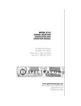
Figure 1 - 1. SSU Modules.
INPUT A and B Modules (2 locations):
These accept synchronization inputs at 2048 kHz (4 per module) and/or 2.048 Mbit/s (2 per
module). One of the modules performs the function and the other ensures concurrently the
redundancy. The SSU is fitted with 2 modules or 1 module (no redundancy) or no INPUT
module if the input is direct to CLOCK module.
CLOCK A and B Modules (2 locations):
These are fitted, as chosen, with four versions of local oscillators in CLOCK-OCXO (STN),
CLOCK-OCXO (STNe), CLOCK-OCXO (SLN), and CLOCK-Rubidium (PRC). The role of the
module is to provide a stable clock from the synchronization inputs of the INPUT boards or from
its own inputs (channel A at 2048 kHz/10 MHz and channel B at 2048 kHz) if INPUT boards are
not installed. Each of the modules is fitted, optionally, with a GPS receiver. Two modules
operating concurrently ensure redundancy. CLOCK modules exist in two versions (factory
configuration): channel A is designed to receive either 10 MHz or 2048 kHz.
DIST Modules (4 locations):
These are available in three versions: DIST-2048 kHz, DIST-2048 kbit/s, DIST T/F (pps-tod-
10 MHz), distributing respectively eight 2048 kHz outputs, or eight 2048 kbit/s outputs, or two
IN P U T
C L O C K M A N A G E R D IS T
A
B
A
B
1 1
2
3
4

Spectracom Corporation EPSILON SSU
User’s Manual 1-5
10 MHz and two 1PPS outputs and two ToD outputs. Output amplifiers are backed up so as to
deliver output signals even in case one of the amplifiers is failing, as the level, in this case, is
only subjected to level decrease.
MANAGEMENT Module (1 location):
This manages configuration parameters and collects states, but is not essential for the SSU
operation in "Running" mode.
1.7
1.71.7
1.7
Maintenance and Supervision Software
Maintenance and Supervision SoftwareMaintenance and Supervision Software
Maintenance and Supervision Software
The SSU apparatus is delivered accompanied by maintenance software SSUWIN running on
PC in Windows environment. This PC is fitted with standard Ethernet RJ45 network interface
and is connected direct to the Ethernet RJ45 connector of the SSU through a crossover cable or
via IP network.
In order to constitute a complete synchronization network, network supervision software
EPSYNC MANAGER is supplied separately. This software is remote controlled from one (or
more) PC / Windows supervision station(s) connected to the SSU via IP network.
Functions of supervision with the SSU are described in the EPSYNC MANAGER user’s manual.
Menus and functions of the SSUWIN software are included in the EPSYNC MANAGER
software.

EPSILON SSU Spectracom Corporation
User’s Manual 1-6
FABRIQUE EN FRANCE PAR TEKELEC SYSTEMES
29 AV DE LA BALTIQUE 91953 LES ULIS FRANCE
RESEAU 36V - 72V ---
4.5A / 2.5A
INPUTS 2048 kHz
H1
H2
H3
H4
INPUTS 2048 kbit/s
B2
B1
OUTPUTS
O17
O18
O25
O26
O3
O4
O5 O6 O7
O11 O12
O13
O14 O15
O19
O20 O21
O22
O23
O27
O28
O29 O30 O31
O8
O16
O24
O32
O1
O2
O9
O10
N
U
R
G
ALARMS
U
R
G
A1
A2
EXTENS.
INPUTS REF
R1
R2
INPUTS GPS
G1
G2
POWER
-48V
-48V
0 V
-48 V
REMOTE CONTROL
RS232
ETHERNET
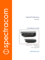
1.8
1.81.8
1.8
Front Panel Connectors
Front Panel ConnectorsFront Panel Connectors
Front Panel Connectors
Figure 1 - 2. Front Panel - Connectors.

Spectracom Corporation EPSILON SSU
User’s Manual 1-7
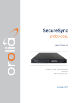
POWER
INPUTS 2048 kHz INPUTS/OUTPUTS 2048 kbit/s INPUTS REF INPUTS GPS
POWER
-48V
-48V
0 V
-48 V
INPUTS 2048 kHz
H1
H2
H3
H4
INPUTS 2048 kbit/s
B2
B1
INPUTS REF
R1
R2
INPUTS GPS
G1
G2
Figure 1 - 3. Front Panel - Connectors (2).
POWER
–48 V DC power supply backed-up input. Paths of both –48 V power supplies are
separate up to powered modules.
INPUTS 2048 kHz (H1, H2, H3, H4)
Inputs from synchronization clocks G.703 at 2048 kHz for INPUT boards (H1, H2,
H3, H4) or for CLOCK boards (H1 and H2 on different pins) without INPUT board.
Each connector powers concurrently both INPUT boards or both CLOCK boards.
H1 is the direct input to CLOCK board (in its 2048 kHz version) and H2 is the direct
input, in 2048 kHz, to CLOCK board (in both versions). See, in Appendix, H1 and
H2 pin assignments in the case of an input to INPUT modules, or direct to CLOCK
modules without INPUT board.
INPUTS/OUTPUTS 2048 kbit/s (B1, B2)
Inputs from synchronization frames G.704 at 2048 kbit/s for INPUT boards. Each
connector powers concurrently both INPUT boards. Input signals are duplicated
through a line interface circuit and output from the same connector.
INPUTS REF (R1, R2)
Inputs from synchronization clocks at 10 MHz for CLOCK boards (in their 10 MHz
version), CLOCK A receiving signals from R1 and CLOCK B from R2. Only used if
reference clock inputs are direct without INPUT board.
INPUTS GPS (G1, G2)
Antenna inputs for GPS receivers on CLOCK boards.

EPSILON SSU Spectracom Corporation
User’s Manual 1-8
OUTPUTS REMOTE CONTROL ALARMS EXTENSION
O1
O2
O9
O10
REMOTE CONTROL
RS232
ETHERNET
N
U
R
G
ALARMS
U
R
G
A1
A2
EXTENS.
Figure 1 - 4. Front Panel - Connectors (3).
OUTPUTS (01 to 032)
Outputs from regenerated clocks (8 receptacles per DIST module) or frames G.704
at 2048 kbit/s (8 receptacles per DIST module) or reference signals at 10 MHz,
1PPS and ToD (6 receptacles per module). One line of connectors corresponds to
one DIST Module with the same numbering.
REMOTE CONTROL (RS232, ETHERNET RJ45)
Access via Ethernet Network to supervision and maintenance functions of the SSU
and RS232 access for network-parameter configuration.
ALARMS (A1, A2)
Outputs of alarm-indicating signals generated by MANAGEMENT board.
EXTENSION
Access to an extension unit for DIST modules for a larger number of outputs.
GROUND
Casing grounding.
Page is loading ...
Page is loading ...
Page is loading ...
Page is loading ...
Page is loading ...
Page is loading ...
Page is loading ...
Page is loading ...
Page is loading ...
Page is loading ...
Page is loading ...
Page is loading ...
Page is loading ...
Page is loading ...
Page is loading ...
Page is loading ...
Page is loading ...
Page is loading ...
Page is loading ...
Page is loading ...
Page is loading ...
Page is loading ...
Page is loading ...
Page is loading ...
Page is loading ...
Page is loading ...
Page is loading ...
Page is loading ...
Page is loading ...
Page is loading ...
Page is loading ...
Page is loading ...
Page is loading ...
Page is loading ...
Page is loading ...
Page is loading ...
Page is loading ...
Page is loading ...
Page is loading ...
Page is loading ...
Page is loading ...
Page is loading ...
Page is loading ...
Page is loading ...
Page is loading ...
Page is loading ...
Page is loading ...
Page is loading ...
Page is loading ...
Page is loading ...
Page is loading ...
Page is loading ...
Page is loading ...
Page is loading ...
Page is loading ...
Page is loading ...
Page is loading ...
Page is loading ...
Page is loading ...
Page is loading ...
Page is loading ...
Page is loading ...
Page is loading ...
Page is loading ...
Page is loading ...
Page is loading ...
Page is loading ...
Page is loading ...
Page is loading ...
Page is loading ...
Page is loading ...
Page is loading ...
Page is loading ...
Page is loading ...
Page is loading ...
Page is loading ...
Page is loading ...
Page is loading ...
Page is loading ...
Page is loading ...
Page is loading ...
Page is loading ...
Page is loading ...
Page is loading ...
Page is loading ...
Page is loading ...
Page is loading ...
Page is loading ...
/