
1
MANUAL P/N 900000111 REV K
User Guide
Networked Frequency Standard
Model NFS-220
P/N 091000001
Revision K
April 2018
Brandywine Communications
1153 Warner Ave
Tustin, CA 92780
(714) 755 1050
(714) 755 0175
http://www.brandywinecomm.com

2
MANUAL P/N 900000111 REV K
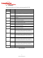
Revision History
REVISION
DATE
COMMENTS
NC
8-13-2008
Original release of NFS220 user guide.
A
02-20-2009
Updated
B
02-19-2010
Change Alarm Status on J9 INPUT/OUTPUT
C
05-20-2011
Update to reflect updated web pages. Incorporated Free run mode
D
12-11-2013
Updated to add firmware and FPGA update procedures
E
01-24-2014
Updated to include power consumption.
F
08-22-2014
Updated to include default IP address information.
G
05-29-2015
Added factory default instructions
H
09-04-2015
Added MIB Description
J
12-15-2015
Corrected information about pulse width
K
04-03-2018
Clarified IRIG local time settings, updated Java installation instructions.

3
MANUAL P/N 900000111 REV K
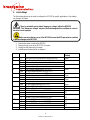
Safety Warnings
WARNING: This unit contains lethal AC voltages. Disconnect the unit from
the AC supply before removing the cover.
WARNING:
The lightning flash with an arrowhead inside of an equilateral triangle is intended to alert the
user to the presence of un-insulated “dangerous voltage” within the product’s enclosure. The
“dangerous voltage” may be of sufficient magnitude to constitute a risk of electrical shock to
people. Do not attempt to repair the unit without first unplugging it.
CAUTION:
The exclamation point inside of an equilateral triangle is intended to alert the user to the
presence of important operation and maintenance instructions in the user guide. This unit
should only be repaired by qualified personnel. Several board assemblies contain static
sensitive devices. Appropriate procedures must be used when handling these board
assemblies.

4
MANUAL P/N 900000111 REV K
Table of Contents
1!Introduction ..................................................................................................................................... 6!
2!Specifications ................................................................................................................................. 7!
2.1!LED Indicators ....................................................................................................................... 10!
2.2!Connections .......................................................................................................................... 11!
2.3!Source Impedance Selection and Signal Termination ......................................................... 12!
3!Unpacking and Installation ........................................................................................................... 13!
3.1!Unpacking ............................................................................................................................. 13!
3.2!Installation ............................................................................................................................. 13!
3.2.1!Mounting ........................................................................................................................ 13!
3.2.2!Power ............................................................................................................................. 13!
3.2.3!Ethernet ......................................................................................................................... 13!
3.2.4!Input Reference Connections ........................................................................................ 13!
3.2.4.1!GPS Antenna ......................................................................................................... 13!
3.2.4.2!External GPS Receiver (Have Quick/1PPS) .......................................................... 15!
3.2.4.3!External 1PPS Receiver ......................................................................................... 15!
3.2.5!NTP Server Connection Example .................................................................................. 16!
3.3!Output signal connections ..................................................................................................... 16!
3.3.1!Signal Connections ........................................................................................................ 16!
3.3.2!Network Connections ..................................................................................................... 16!
3.3.2.1!Discovering the automatically assigned NFS-220 IP address ................................ 16!
3.3.2.2!Changing NFS220 Network IP address using Internet Explorer ............................ 17!
3.3.2.3!Latest Version of Java Software ............................................................................. 19!
4!Configuration ................................................................................................................................ 20!
4.1!Setup ..................................................................................................................................... 20!
4.1.1!System ........................................................................................................................... 20!
4.1.2!IP Address ..................................................................................................................... 21!
4.1.3!SNMP Download MIB File ............................................................................................. 21!
4.2!Status .................................................................................................................................... 23!
4.2.1!Local Time ..................................................................................................................... 23!
4.2.2!Reference Status ........................................................................................................... 23!
4.2.3!Oscillator Status ............................................................................................................. 24!
4.2.4!Fault Status .................................................................................................................... 24!
4.3!Time ...................................................................................................................................... 25!
4.3.1!Serial Output (TOD) ....................................................................................................... 26!
4.3.2!Time Zone Settings ........................................................................................................ 27!
4.3.2.1!Standard Time Zone settings ................................................................................. 27!
4.3.2.2!Special case – 30 minute time zone setting. .......................................................... 27!
4.3.3!Daylight Saving Time ..................................................................................................... 28!
4.3.4!Daylight Saving Time (Advanced) ................................................................................. 28!
4.3.5!Setting the IRIG Time Code format. .............................................................................. 29!
4.4!Password .............................................................................................................................. 30!
4.4.1!Password ....................................................................................................................... 30!
4.5!Reference .............................................................................................................................. 31!
4.5.1!Reference Selection ...................................................................................................... 32!
4.5.1.1!GPS Reference (Factory default) ........................................................................... 32!

5
MANUAL P/N 900000111 REV K
4.5.1.2!Have Quick & 1PPS Reference .............................................................................. 33!
4.5.1.3!External 1PPS Only Reference .............................................................................. 33!
4.5.1.4!Free-Run Reference ............................................................................................... 33!
4.5.2!10 MHz Output Level Settings ...................................................................................... 34!
4.5.3!Output Timing Setting .................................................................................................... 35!
4.5.3.1!Setting 1PPS Pulse width ....................................................................................... 35!
4.5.3.2!Setting 1PPS Pulse delay ...................................................................................... 36!
4.6!Help ....................................................................................................................................... 37!
4.7!Firmware Upgrade ................................................................................................................ 37!
4.8!FPGA Upgrade ...................................................................................................................... 38!
4.9!Webpage Upgrade ................................................................................................................ 40!
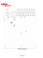
5!Drawings ....................................................................................................................................... 45!
6!Link Settings ................................................................................................................................. 48!
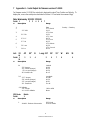
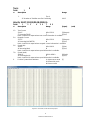
7!Appendix A – Serial Output for firmware version ### ................................................................... 50!
8!Appendix B – MIB File .................................................................................................................. 52!
Table of Figures
Figure 1 Typical NFS-220 NTP Server Network Connection .............................................................. 16!
Figure 2 NFS-220 console port start-up string .................................................................................... 17!
Figure 3 Browser settings for NFS-220 ............................................................................................... 17!
Figure 5: Setup ................................................................................................................................... 20!
Figure 6 Download MIB file ................................................................................................................. 21!
Figure 7 NFS-220 MIB (sample) ......................................................................................................... 22!
Figure 8: Status ................................................................................................................................... 23!
Figure 9: Time ..................................................................................................................................... 25!
Figure 10 Standard IRIG Formats ....................................................................................................... 29!
Figure 11: Password ........................................................................................................................... 30!
Figure 12 Reference Tab .................................................................................................................... 31!
Figure 13 Selecting the NFS-220 reference ....................................................................................... 32!
Figure 14 GPS Fixed/Mobile Selection ............................................................................................... 32!
Figure 15 Manual Setting of Time in NFS-220 .................................................................................... 33!
Figure 16 Manual Setting of Time in NFS-220 .................................................................................... 34!
Figure 17 Setting NFS-220 10 MHz output level ................................................................................ 35!
Figure 18 Output Timing Settings ....................................................................................................... 35!
Figure 19 - Serial Time, Position and Velocity output. ........................................................................ 47!

6
MANUAL P/N 900000111 REV K
1 Introduction
The NFS220 is a precision time and frequency standard that uses the Global Positioning System (GPS).
It is designed for use in WI-FI, Wi-Max, satellite communications, telecommunications and military
communication applications.
The NFS220 utilizes a high performance 16 channel GPS receiver. An automatic position-averaging feature
enables the best use of GPS when operating in a fixed location.
The NFS220 is fitted with an internal back up oscillator that is continuously calibrated to GPS using an
advanced algorithm, providing optimal frequency control of the oscillator. This ensures that the highest time
and frequency accuracy is maintained if no satellites can be tracked, and ensures an ultra stable, low noise
frequency reference.
The basic NFS220 includes a precision OCXO frequency standard, while TCXO and Rubidium oscillators
are available options that offer a variety of price and performance options. An option with a low noise OCXO
phase locked to a Rubidium is also available, combining the low noise characteristic of the OCXO with the
long term stability of a Rubidium oscillator.
The NFS220 provides “at a glance” status indication via front panel LED’s and can be integrated with other
management systems using Ethernet and serial ports.
The NFS220 provides simple integration into military platforms by allowing synchronization from Have Quick
time code, which is available on military SA-ASM GPS receivers such as the DAGR(AN/PSN-13) or
PLGR(AN/PSN-11). The NFS220 also generates Have Quick and 1PPS signals compatible with ICD-GPS-
060.
The integrated Ethernet interface provides Network Time Protocol (NTP) synchronization to other connected
computers. In addition to NTP, the NFS220 Ethernet interface contains a built-in web server that allows the
NFS220 to be controlled using a standard web browser such as Internet Explorer or Chrome. Simple
Network Management Protocol (SNMP) allows easy integration of the NFS220 with industry standard
network management systems.
The NFS220 provides three 1PPS time mark outputs. A unique feature allows precise controlled delays to
be inserted into these outputs to compensate for cable- and other propagation delays. Compensation delay
is independent for each output and has <1ns resolution.
Serial time code outputs are provided to allow time synchronization to be distributed to computers, displays,
and other equipment requiring precision time. Two outputs are dedicated to Have Quick time code. Two
outputs (one modulated, one DC level shift) may be user selected from IRIG A, IRIG B, IRIG E or IRIG G.
Four low phase noise 10 MHz sine wave outputs from the disciplined oscillator are provided. Signal
amplitude is able to be set using the software available.
All outputs are provided with activity detectors. Loss of any output is indicated by means of an individual
front panel alarm LED as well as through the network interface or a discrete alarm output.

7
MANUAL P/N 900000111 REV K
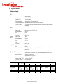
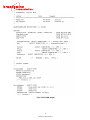
2 Specifications
Reference Inputs
GPS
Receiver Type
Parallel 16 Channel. All-in-view satellites tracked continuously and
simultaneously
Satellite Signal
GPS L1 1575.42 MHz
Satellite Code
C/A 1.023 MHz
Warm Start
<10 sec(Open Sky)
Autonomous Start
<60 seconds Cold Start (Open Sky)
Cold Start Requirement
Automatic: No input of time or position required
Position Accuracy
2.4 m horizontal, 5 m altitude with respect to WGS84 after 24 hour position
averaging
Antenna Connector
BNC Female
Have
Quick
Signal Type
Have Quick II per ICD-GPS-060
Input Impedance
50 ohm
Level
0-5V
TFOM Threshold
4
Connector
DB-9 (J-10)
External
1PPS
Signal Type
1PPS
Input Impedance
50 ohm
Level
2.5 - 5V
Maximum Frequency
Error
2x10⁻⁹
Connector
DB-9 (J10)
Input Modes
GPS
Default
Have Quick/1PPS
Uses 1PPS for synchronization, Time of Day is loaded automatically from
Have Quick
External 1PPS only
Uses 1PPS for synchronization, Time of Day is loaded manually by user
System Accuracy
Specifications are based on GPS mode tracking satellites unless noted.
Timing Accuracy
± 100 ns. absolute UTC
Std Deviation 15ns (OCXO)
Timing Accuracy
(holdover mode, ± 5ºC)
< 25 µsec/day (OCXO)
< 2 µsec /day (Rb2)
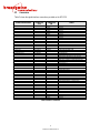
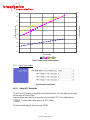
Frequency stability)
See tables below
Oscillator Option
Stability
-10 to 50 °C
Allan Variance
1s
10s
100s
1000s
10000s
1 day
TCXO
2.5x10⁻⁶
1x10⁻⁷
1x10⁻⁷
1x10⁻⁷
5x10⁻⁸
2x10⁻⁹
1x10-11
OCXO (std)
3x10⁻⁹
5x10-12
8x10-12
1x10-11
1x10-11
5x10-12
1x10-12
Rb1
7x10⁻¹⁰
3x10-11
1.6x10⁻¹¹
8x10-12
<1x10-12
Rb2
4x10⁻¹⁰
1x10-11
3x10-12
1x10-12
<1x10-12
Rb/OCXO
4x10⁻¹⁰
5x10-12
1x10-11
3x10-12
<1x10-12

8
MANUAL P/N 900000111 REV K
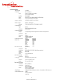
System Outputs
1PPS Output
3 Outputs
Connector
BNC (2) DB9 (1)
Level
0-10V for output 1 and 2 (BNCs)
0-5V for output 3 (DB9)
On Time
Rising Edge
Width
100ns to 6.5 ms software settable in 100ns steps
Delay
-0.5 to +0.5 seconds in 1 ns steps
Individually settable for each output
Network Interface
Interface Type
10BaseT, Half-Duplex.
Protocols
TCP/IP, UDP, NTPv3, HTTP, SNMP v1, DHCP
Serial Interface
Type
RS232
RS422 link selectable by user
Baud rate
115200, N,8,1
Sine Wave Outputs
Outputs
4 independently buffered outputs with software level adjustment
Connector
BNC
Frequency
10MHz
Level
9-16dBm into 50 ohm
Software settable
Phase Noise (OCXO,
RB/OCXO)
Offset dBc/√/Hz
1Hz -90
10Hz -120
100Hz -130
1kHz -140
10kHz -150
100kHz -155
Time Code 1 Output
(Modulated)
Connector
BNC
Code Type
IRIG A135, B125, E115, G145 software selected
Control
Functions
IEEE 1344
Level
3 V p-p into 600 ohm
Time Code 2 Output
(DCLS)
Connector
DB9 J9-2
Code Type
IRIG A005, B005, E005, G005
Selection
same as modulated code
Levels
DC Level Shift (0-5V)
Time Code 3,4 Output
Connector
BNC (1) DB9 (1)
Code Type
Have Quick
per ICD-GPS-060
Levels
0-10V for output 1 (BNC)
0-5V for output 2 (DB9)
Alarm Status
Voltage free relay changeover contacts. Link settable for +5V alarm out
Status Indicator LED’s
Power
Tracking Satellites
Valid Time

9
MANUAL P/N 900000111 REV K
Holdover/12hr Holdover alarm
Output Good/Fail ( 8 LEDs)
Environmental
Temperature
Instrument: -10 to +50 °C
Antenna: -40 to +85 °C
Humidity
95% non condensing
Power
Consumption
85-265VAC 50/60Hz
40 Watts
Optional
12VDC, 24VDC, -48VDC, 125VDC
Dimensions
19” rack mount
1.75” (1U) height, 6.5“ depth
Weight
3.5 lb. typical
EMC Emission
EN55022
FCC Chapter 15 Subpart B, Class A
EMC Immunity
EN55024

10
MANUAL P/N 900000111 REV K
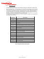
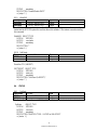
2.1 LED Indicators
Table 1 below describes each LED indicator on the front panel of the NFS-220.
LED
COLOR
COMMENT
Power
Green
Indicates Prime Power is applied to the NFS220.
Time Valid
Green
Indicates that the unit has been synchronized to an external reference.
Amber
Indicates that the unit is in Holdover.
Tracking
Satellites
Green
Indicates that the GPS receiver is tracking satellites OR that the Have
Quick time code has been successfully decoded if HQ is selected as a
reference.
Red
Indicates that the NFS220 has not had a valid reference for 12 hours.
Off
Indicates that the NFS220 is not tracking satellites or successfully
decoding HQ.
IRIG
J8
Green
Indicates that the IRIG time code output on J8 is operating.
Red
Indicates that the IRIG time code output on J8 has failed or that there
is an excessive load on the output.
HQ
J7
Green
Indicates that the Have Quick time code output on J7 is operating.
Red
Indicates that the Have Quick time code output on J7 has failed or that
there is an excessive load on the output.
1PPS
J6
Green
Indicates that the 1PPS pulse output on J6 is operating.
Red
Indicates that the 1PPS pulse output on J6 has failed or that there is
an excessive load on the output.
1PPS
J5
Green
Indicates that the 1PPS pulse output on J5 is operating.
Red
Indicates that the 1PPS pulse output on J5 has failed or that there is
an excessive load on the output.
10MHz
J4
Green
Indicates that the 10MHz output on J4 is operating.
Red
Indicates that the 10MHz output on J4 has failed, that there is an
excessive load on the output, or that the output is connected to a
cable that is improperly terminated and is causing a reflection on the
line.
10MHz
J3
Green
Indicates that the 10MHz output on J3 is operating.
Red
Indicates that the 10MHz output on J3 has failed, that there is an
excessive load on the output, or that the output is connected to a
cable that is improperly terminated and is causing a reflection on the
line.
10MHz
J3
Green
Indicates that the 10MHz output on J2 is operating.
Red
Indicates that the 10MHz output on J2 has failed, that there is an
excessive load on the output, or that the output is connected to a
cable that is improperly terminated and is causing a reflection on the
line.
10MHz
J3
Green
Indicates that the 10MHz output on J1 is operating.
Red
Indicates that the 10MHz output on J1 has failed, that there is an
excessive load on the output, or that the output is connected to a
cable that is improperly terminated and is causing a reflection on the
line.
Ethernet
J11
Yellow
Activity
Green
Link
Table 1 LED Indicators

11
MANUAL P/N 900000111 REV K
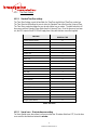
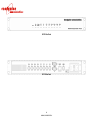
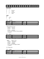
2.2 Connections
Table 2 shows the signal interface connections provided on the NFS-220.
CONNECTOR REFERENCE
CONNECTOR
TYPE
CONNECTOR
PIN
SIGNAL
J1 10 MHz OUTPUT 1
BNC FEMALE
CENTER
10 MHz
SHIELD
GROUND
J2 10 MHz OUTPUT 2
BNC FEMALE
CENTER
10 MHz
SHIELD
GROUND
J3 10 MHz OUTPUT 3
BNC FEMALE
CENTER
10 MHz
SHIELD
GROUND
J4 10 MHz OUTPUT 4
BNC FEMALE
CENTER
10 MHz
GROUND
J5 1 PPS OUTPUT 1
BNC FEMALE
CENTER
1 PPS
SHIELD
GROUND
J6 1 PPS OUTPUT 2
BNC FEMALE
CENTER
1 PPS
SHIELD
GROUND
J7 HAVE QUICK OUT
BNC FEMALE
CENTER
HAVE QUICK II TIME CODE per ICD-GPS-060
SHIELD
GROUND
J8 IRIG OUT
BNC FEMALE
CENTER
MODULATED IRIG TIME CODE
SHIELD
GROUND
J9 INPUT/OUTPUT
DB-9 FEMALE
1
NO CONNECTION
2
DC LEVEL SHIFT IRIG TIME CODE
3
HAVE QUICK II TIME CODE per ICD-GPS-060
4
ALARM OUT CONTACT-CLOSED ON ALARM
5
ALARM OUT CONTACT-CLOSED ON NO-ALARM
6
GROUND
7
1 PPS OUTPUT 3
8
GROUND
9
ALARM OUT COMMON
J10 CONSOLE PORT
DB-9 MALE
1
HAVE QUICK INPUT (EXTERNAL REFERENCE)
2
RS232 RECEIVE DATA
3
RS232 TRANSMIT DATA (SERIAL DATA)
4
1PPS INPUT (EXTERNAL REFERENCE)
5
GROUND
6
RS422 RECEIVE DATA -
7
RS422 RECEIVE DATA +
8
RS422 TRANSMIT DATA – (SERIAL DATA)
9
RS422 TRANSMITDATA + (SERIAL DATA)
J11 ETHERNET
RJ-45
1
TX+
2
TX-
3
RX+
4
-
5
-
6
RX-
7
-
8
-
J12 ANTENNA
BNC FEMALE
CENTER
GPS L1, +5V power for antenna
SHIELD
GROUND
Table 2 Interface Connections

12
MANUAL P/N 900000111 REV K
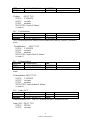
2.3 Source Impedance Selection and Signal Termination
Signal/Connector
Connector
Link Setting
Source Impedance
Recommended Load
Impedance
Factory Setting
10 MHz
J1
N/A
50 ohm
50 ohm
N/A
10 MHz
J2
N/A
50 ohm
50 ohm
N/A
10 MHz
J3
N/A
50 ohm
50 ohm
N/A
10 MHz
J4
N/A
50 ohm
50 ohm
N/A
1PPS 1
J5
LK5 on
Low Z
50 ohm
LK5 off
50 ohm
50 ohm
ü
1PPS 2
J6
LK6 on
Low Z
50 ohm
LK6 off
50 ohm
50 ohm
ü
1PPS 3
J9-7
LK7 on
Low Z
50 ohm
LK7 off
50 ohm
1 kohm
ü
Have Quick 1
J7
LK2 on
Low Z
50 ohm
LK2 off
50 ohm
50 ohm
ü
Have Quick 2
J9-3
LK3 on
Low Z
50 ohm
LK3 off
50 ohm
1 kohm
ü
IRIG modulated
J8
N/A
6 ohm
600 ohm
N/A
IRIG DCLS
J9-2
LK3 on
Low Z
50 ohm
LK3 off
50 ohm
1 kohm
ü
Table 3 Source Impedance and Recommended Signal Terminations

13
MANUAL P/N 900000111 REV K
3 Unpacking and Installation
3.1 Unpacking
Remove the NFS-220 from the shipping carton. The following items should be included in the
shipment:
• 1 NFS-220
• 1 GPS antenna
• 1x 100 feet of coaxial antenna cable
• 1 user guide (CD-ROM)
3.2 Installation
3.2.1 Mounting
The NFS220 can be installed into a 19” rack mount cabinet either using rack slides or only using the
front panel flanges. For static applications, the short depth and light weight of the NFS-220 ensures
that the front panel is not stressed when only the front panel is used for support.
If the NFS220 is installed on a mobile platform and must survive shock and vibration, the use of
slides is recommended. Slides are installed using 10-32 UNF-2B hardware.
Optional Rack Mount Slides:
P/N 002000123, SLIDE, RACK, 24", 21" TRAVEL, 85 LB
P/N 002000150, SLIDE, RACK, 28", 27" TRAVEL, 80 LB
Original Manufacturer: General Devices Chassis Trak Type C300.
3.2.2 Power
Insert the power cord of the NFS-220 into an electrical socket to power up the unit. The Power LED
indicator will illuminate green.
3.2.3 Ethernet
Connect one end of an Ethernet patch cable to the NFS-220 Ethernet port J11. Connect the other
end of the Ethernet cable to your network with an Ethernet hub or switch.
3.2.4 Input Reference Connections
3.2.4.1 GPS Antenna
Connect the GPS antenna to the J12 Antenna BNC connector on the rear panel of the unit. The
GPS antenna must be located in a suitable location with a clear view of the sky. In most cases, the
GPS signals do not penetrate buildings. Use the cable provided in the shipment to connect the GPS

14
MANUAL P/N 900000111 REV K
antenna and NFS-220. In the event that a longer cable is required, a low loss cable must be used so
that the total signal attenuation at 1575 MHz is < 20 dB. For more information on suitable cables
contact Brandywine Communications.
q Location
Several factors need to be considered when installing the GPS antenna. In most cases, the antenna
is mounted externally (outdoor) and exposed to the elements. A good quality coaxial cable of 50
ohm impedance is required to connect the GPS antenna to the NFS-220. The cable provides two
functions, which are to conduct the GPS RF signals (1575.42 MHz) that are received from the GPS
antenna to the NFS-220 and to conduct the DC bias voltage (5 VDC) provided by the NFS-220 to the
LNA (low noise amplifier) contained inside of the GPS antenna. The antenna should be mounted
securely, with a clear view of the sky, and with the top of the antenna pointing upward. In some
installations it may not be possible to mount the antenna such that the antenna has a clear 360
degree view of the sky. In such cases pick the location with the best view of the sky.
q Exposure to High RF Fields
Some installations may occur in locations where a variety of high power transmitters and antennas
are located. The GPS antenna should not be directly exposed to or bombarded with high level RF
energy. In such cases, the antenna should be located either above, below, or to the side of these
high power RF transmission antennas.
q Lightning Protection
The NFS-220 does not provide any inherent protection against lightning strikes. In general, lightning
protection (when desired or needed) is provided by an externally mounted protection device that is
designed to shunt the high voltage transient to a well established earth ground. Lightning arresting
devices designed for use with the GPS antenna system are available at Brandywine Communications
(P/N 001000914).
q RF Loss
The most important source of signal loss is the RF signal attenuation experienced in the cable. The
amount of attenuation is related to the type (quality) of coaxial cable and cable length. The antenna
provides about 30 dB of gain to the received GPS signal. The purpose of this gain is to offset the
loss that is experienced in the cable between the GPS antenna and NFS-220. It is recommended
that the overall antenna system gain (antenna gain - cable loss) be between 10 dB - 33 dB. Using an
antenna with 30 dB of gain allows for about 20 dB of cable loss. The NFS-220 is shipped with 100’ of
Belden 8240 antenna cable with a cable loss of approximately 18 dB. For distances beyond 100’,
Brandywine recommends low loss Belden 9914 with a loss of 5.84 dB/100ft
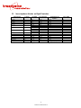
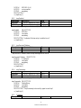
Standard antenna cable using this configuration is available from Brandywine as shown in Table 4.
For distances beyond 330’, an in-line amplifier is required.
q Tempest Facilities/Extremely Long Cable Runs
For applications where no conductive penetration of EMC shielding can be tolerated or for extremely
long cable runs, Brandywine Communications offers a remotely powered fiber optic antenna link.

15
MANUAL P/N 900000111 REV K
This comprises two external units. The remote down-converter and fiber unit is connected to the
antenna and it converts the GPS RF signal to an optic signal at lower frequencies that is suitable for
transmissions over a fiber optic cable. The local fiber and up-converter unit accepts the optical signal
and converts it back into an electrical RF signal that is processed by the NFS-220. Please note that
the unit does not require calibration.
PART NUMBER
CABLE LENGTH
CABLE TYPE
002-0037
100 feet
RG58 (supplied)
002-0040
150 feet
RG8
002-0052
250 feet
RG8
002-0039
330 feet
RG8
051000001
In-line amplifier 20 dB
TNC/TNC connectors
002-0065
Fiber optic cable converter up to
1500 meters
Multi-mode fiber optic
Table 4 NFS-220 Antenna Cable options
Please note that it can take up to five (5) minutes for the unit to lock on to a GPS signal after
powering up. Until then, the unit will not be sending out valid time.
The unit must have at least four (4) GPS satellites in view at all times in order to generate valid
time.
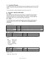
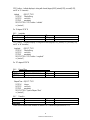
3.2.4.2 External GPS Receiver (Have Quick/1PPS)
The NFS-220 can also be synchronized to an external GPS receiver such as the AN/PSN-13
Defence Advanced GPS Receiver (DAGR), or AN/PSN-11 PLGR .
Both of these receivers incorporate a 1PPS Time Mark and Have Quick time code output that are
used by the NFS220 as references. Both signals are required for automatic operation. The NFS-220
requires that the TFOM is ≤4 before it will accept the time.
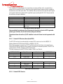
The cable connections to the NFS-220 are shown in Table 5 and Table 6:
AN/PSN-13 DAGR
Signal Name
Direction
NFS220 (J10)
J2-7
Have Quick
>
1
J2-6
1PPS
>
4
J2-11
Signal Return
>
5
Table 5 Cable Connection to DAGR
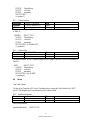
AN/PSN-11 PLGR
Signal Name
Direction
NFS220 (J10)
7
Have Quick
>
1
6
1PPS
>
4
11
Signal Return
>
5
Table 6 Cable Connection to PLGR
3.2.4.3 External 1PPS Receiver

16
MANUAL P/N 900000111 REV K
The NFS -220 can also be synchronized to an external receiver that incorporates a 1PPS Time Mark
only as a reference. A accurate manual time entry is necessary in this case. See section 4.5.1.3
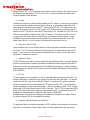
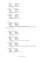
3.2.5 NTP Server Connection Example
The NFS-220 is suitable for use as a Network Time Server, supporting Network Time Protocol (NTP).
An example of the deployment of the NFS-220 in this role is shown below.
Figure 1 Typical NFS-220 NTP Server Network Connection
3.3 Output signal connections
3.3.1 Signal Connections
The output signals from the NFS-220 should be connected as required using appropriate
connectors/cables. The cable should be terminated in the impedance shown in Table 3 for optimum
operation. In particular, the 1PPS signal has very fast rise times, and to prevent unwanted reflections,
these outputs should be terminated correctly in 50 ohm
All BNC connectors are 50 ohm.
3.3.2 Network Connections
The NFS-220 is shipped with a label that indicates the IP address stored in the unit. The default
settings are:
• IP Address: Automatic – set by DHCP server
• Subnet Mask: Automatic – set by DHCP server
• Gateway:Automatic – set by DHCP server
To change the network address, the user may use a web browser, or the console port. The two
processes are described below.
If the NFS-220 cannot find a DCHP server on the network, it will set itself to the default IP
Address of 192.168.1.220, unless it has already been set to an existing static IP.
The NFS-220 Plus will display the IP address on the front panel display as it powers up.
3.3.2.1 Discovering the automatically assigned NFS-220 IP address
Workgroup
Switch
NFS-220
LAN
Enterprise Server
(NTP Stratum 2)
NTP
Clients
Local NTP
Clients

17
MANUAL P/N 900000111 REV K
In the default configuration, the NFS-220 is automatically assigned an IP address by the network’s
DHCP server. If it cannot find a DHCP server, it will set itself to 192.168.1.220. In order to use a
web browser to control the unit, this address must be discovered.
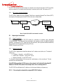
This can be done, either by using the “Microchip Ethernet Device Discoverer” application from a
computer on the same network as the unit, or by connecting a computer to the NFS-220 console port
J10, via RS232, and using a terminal program such as HyperTerminal or Tera Term.
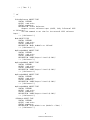
1. Configure the terminal program to accept ASCII data at 115,200 baud, No Parity, 8
bits/character, 1 stop bit (115200, N, 8,1); No Flow Control.
2. Cycle Power to the NFS-220.
3. A short string will be broadcast by the NFS-220 that has the IP address of the unit.
4. Note that in the example shown in Figure 2 the IP address changed upon power up from
192.168.2.206 (previous setting) to 192.168.1.129 which is the new address that the DHCP
server assigned to it upon power up.
Figure 2 NFS-220 console port start-up string
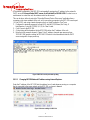
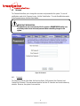
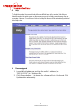
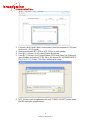
3.3.2.2 Changing NFS220 Network IP address using Internet Explorer
Enter the IP address of the NFS-220 into the address bar of a web browser running on a computer
that is connected to the same network as the NFS-220, as shown in Figure 3
Figure 3 Browser settings for NFS-220

18
MANUAL P/N 900000111 REV K
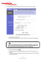
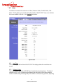
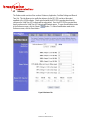
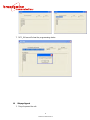
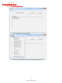
The browser page for the NFS-220 will load. Select the tab for Setup, as shown in Figure 4.
Figure 4 Setting IP address through the browser
1. Check the Box to Disable DHCP
2. Enter the desired parameters for the device IP address, the Subnet Mask and the gateway.
If you enter an invalid IP address, subnet mask and gateway, you may not be
able to reach the NFS-220 using a web browser. Carefully check this information prior to
entry, and check with your network administrator for the correct settings.
3. Click on the Submit button.
4. Note that the browser will not reload the page, because the NFS-220 IP address has now
changed.
5. Set the browser to the newly configured IP address and confirm that the NFS-220 IP address
has changed as desired.

19
MANUAL P/N 900000111 REV K
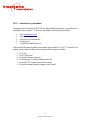
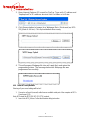
3.3.2.3 Latest Version of Java Software
To properly control and monitor the NFS-220 via a web browser based interface, Java software must
be installed on your computer. To obtain the Java software, follow the steps given below.
1. Go to http://www.java.com.
2. Click on the Download link.
3. Click on the Java Download link.
4. Download Java.
5. Complete the installation process.
Please note that the oldest acceptable Java software version number is 1.4.2_05. To check the Java
software version number installed on your computer, follow the steps given below.
1. Go to ‘Start’.
2. Go to ‘Control Panel’.
3. Go to ‘Add or Remove Programs’.
4. Scroll through the ‘Currently installed programs’ list.
5. Locate the ‘J2SE Runtime Environmental’ program.
6. The version number follows the program’s name in step 5.

20
MANUAL P/N 900000111 REV K
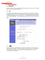
4 Configuration
Please note that the unit will automatically reboot when a serious error or lock up occurs. This allows
the unit to reset and run instead of locking up.
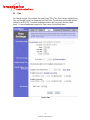
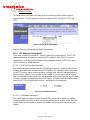
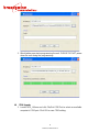
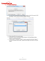
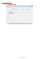
4.1 Setup
The Setup tab consists of two sections, the System and IP Address. This tab allows you to modify
setup information for the NFS-220. Please note that a Class C Network is being used therefore valid
IP addresses are between 192.0.0.0 to 223.255.255.0. To save all modifications made to the Setup
screen, click the Submit button. To undo all modifications made to the Setup screen, click the Reset
button.
Figure 5: Setup
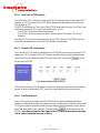
4.1.1 System
The System section consists of two fields, the Version and Unit Location. The Version refers to the
version number of the firmware. The Unit Location refers to the location of the unit. A maximum of
127 characters may be entered in the Unit Location field. Entering apostrophes (‘) in the Unit
Location field is not recommended.
Page is loading ...
Page is loading ...
Page is loading ...
Page is loading ...
Page is loading ...
Page is loading ...
Page is loading ...
Page is loading ...
Page is loading ...
Page is loading ...
Page is loading ...
Page is loading ...
Page is loading ...
Page is loading ...
Page is loading ...
Page is loading ...
Page is loading ...
Page is loading ...
Page is loading ...
Page is loading ...
Page is loading ...
Page is loading ...
Page is loading ...
Page is loading ...
Page is loading ...
Page is loading ...
Page is loading ...
Page is loading ...
Page is loading ...
Page is loading ...
Page is loading ...
Page is loading ...
Page is loading ...
Page is loading ...
Page is loading ...
Page is loading ...
Page is loading ...
Page is loading ...
Page is loading ...
Page is loading ...
Page is loading ...
Page is loading ...
Page is loading ...
Page is loading ...
Page is loading ...
Page is loading ...
Page is loading ...
-
 1
1
-
 2
2
-
 3
3
-
 4
4
-
 5
5
-
 6
6
-
 7
7
-
 8
8
-
 9
9
-
 10
10
-
 11
11
-
 12
12
-
 13
13
-
 14
14
-
 15
15
-
 16
16
-
 17
17
-
 18
18
-
 19
19
-
 20
20
-
 21
21
-
 22
22
-
 23
23
-
 24
24
-
 25
25
-
 26
26
-
 27
27
-
 28
28
-
 29
29
-
 30
30
-
 31
31
-
 32
32
-
 33
33
-
 34
34
-
 35
35
-
 36
36
-
 37
37
-
 38
38
-
 39
39
-
 40
40
-
 41
41
-
 42
42
-
 43
43
-
 44
44
-
 45
45
-
 46
46
-
 47
47
-
 48
48
-
 49
49
-
 50
50
-
 51
51
-
 52
52
-
 53
53
-
 54
54
-
 55
55
-
 56
56
-
 57
57
-
 58
58
-
 59
59
-
 60
60
-
 61
61
-
 62
62
-
 63
63
-
 64
64
-
 65
65
-
 66
66
-
 67
67


Ask a question and I''ll find the answer in the document
Finding information in a document is now easier with AI
Other documents
-
 Orolia Epsilon Clock EC31M User manual
-
Meinberg IMS-M1000-S User manual
-
-
-
-
Meinberg IMS LANTIME M1000S User manual
-
-
-
-
 Orolia SecureSync 2400 Time and Frequency Synchronization System User manual

