Page is loading ...

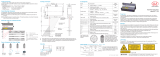
Connection Guide
IF2030/PNET
Interface module

Connection Guide IF2030/PNET
2
1 General
This document describes how to connect IF2030/PNET to SIMATIC S7 controllers.
IF2030/PNET is an interface module to connect Micro-Epsilon sensors (controller) equipped
with either an RS422 or RS485 interface to PROFINET. This is how these devices can be
integrated into Siemens PLC environments. This guide refers to the STEP 7 V.14
programming software which is part of the TIA Portal framework. Other versions may differ in
the design of the graphical user interface and their range of features.
2 System design
Please prepare the following equipment to connect an IF2030/PNET-compatible sensor
(controller) with a Siemens PLC environment:
CPU module of the Siemens SIMATIC S7 series
Micro-Epsilon sensor (controller) with RS422 or RS485 interface, incl. corresponding
connection cable
IF2030/PNET interface module, incl. GSDML file (download from the Micro-Epsilon
website or data storage device included in the scope of supply)
Computer with installed STEP 7 software (TIA Portal)
2x Ethernet cables
Power supply PS2020 (optional)
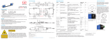
Please note that the connectable Micro-Epsilon sensors (controllers) are stored in the
IF2030/PNET firmware. The figure below schematically shows you how to connect the
previously mentioned components.

Connection Guide IF2030/PNET
3
3 Basic settings and configuration
3.1 Importing IF2030/PNET into the software
1. Start the TIA (Totally Integrated Automation) Portal. Therefore, either double-click the TIA
Portal icon on your desktop or call up the framework via the Start Menu.
2. Click the button Create new project which is at the top left of the Start portal
view. Enter a project name and confirm by clicking the Create button.
3. Switch to the Devices & networks portal.

Connection Guide IF2030/PNET
4
4. Click Add new device. Select the S7 CPU series you are using in the device list and
click the Add button. Make sure that the checkbox Open device view on the bottom left
of the window is activated.
Hint: Identify your CPU module based on the order number on the S7 device, its packaging,
or the delivery note. Also select the correct firmware Version.
Note: Here, you can also change the default Device name PLC_1. However, this is not
mandatory.
5. The software switches automatically to the Project view and displays the Working
window (center of screen) in the Device view. Below, you can find the Inspector
window which shows the parameterization options of the selected PLC in the Properties
register.
Note: The TIA Portal automatically assigns the IP address and subnet mask. You can
manually adjust these data here (General PROFINET interface Ethernet
addresses) if necessary and save them by clicking the Save project button
(top left corner in the Toolbar).

Connection Guide IF2030/PNET
5
6. Import the GSDML file. In general, it contains information about a PROFINET device
(properties such as supported sensors and parameters of IF2030/PNET) and is provided by
Micro-Epsilon. This file is necessary for the PROFINET controller and must be integrated into
the corresponding configuration software.
Navigate in the Main menu to Options Manage general station description
files (GSD).
7. Select the path for the file „GSDML-Vx-MICRO-EPSILON-IF2030.xml“ in the open Dialog
box and click the Install button.

Connection Guide IF2030/PNET
6
8. After successful installation, switch to the Project view again by clicking Devices &
networks in the Project tree on the left side of the screen.
9. Make sure that IF2030/PNET has been integrated correctly.
Use the Hardware catalog (within the Task window) next
to the Working window for this purpose. The catalog shows
all hardware components which can be configured with the
current STEP 7 version.
Follow this path: Other field devices PROFINET IO
I/O MICRO-EPSILON MESSTECHNIK GmbH PNS
IF2030/PNET.

Connection Guide IF2030/PNET
7
3.2 Unique integration of IF2030/PNET into the PROFINET network
10. Switch to the Network view of the Working window and add IF2030/PNET from the
Hardware catalog by drag and drop.
11. Connect the green Ethernet socket of IF2030/PNET with the one of the PLC by clicking
one of the green boxes with the left mouse button. Hold the button and draw the resulting
line to the other green box in order to create a PROFINET subsystem.
12. Switch to Device view, double-click your IF2030/PNET and assign a (device) Name in
the Inspector window (tab Properties General). This name is used for
identification in the PROFINET network and as address. Therefore, it must be unique
throughout the system!
Note: This is one of several possibilities to change the device name.

Connection Guide IF2030/PNET
8
13. The change of name has
to be communicated to the
PROFINET network. Right-click
IF2030/PNET to reach the
function Assign device
name in the displayed
Shortcut menu.
14. Click the Update list button in the open Dialog box in order to display all possible
devices in the PROFINET network corresponding to the profile. Select the line containing the
IF2030/PNET, which should be given a new name, in the appearing list (Status “Device
name is different”). Finally, click the Assign name button.
Hint: If you activate the Flash LED checkbox in the orange highlighted area you can verify
which device you are currently addressing. This is especially helpful in larger networks.

Connection Guide IF2030/PNET
9
3.3 Defining inputs and outputs of IF2030/PNET
15. Add modules to IF2030/PNET. In the Hardware catalog on the right-hand side, first
select the appropriate input module for the payload. Drag it to the first free Slot in the
Device overview. Then select the output module “Basic configuration” and place it in the
next free spot.
Note: IF2030/PNET determines the amount of cyclic data to be transmitted itself and selects
a suitable module. The module must match the one selected in TIA. The determination
results from the logic described below.
15.1 Determination of payload data: If a value != 0 is entered in the Datasize object (hex
address 0x2022), this value is used as data quantity per sensor for selecting the module.
Otherwise the following applies for (►Operating Instructions 4.2.2)
ME Bus / RS485 sensors: IF2030/PNET asks the first sensor at boot time for the
amount of payload data and multiplies it by the number of sensors.
MEO / RS422 device: IF2030/PNET cannot determine the amount of data, which is
why the 128 Bytes input module is selected by default.

Connection Guide IF2030/PNET
10
15.2 Debug header: If the Cyclic Status Information is activated in the settings at
boot time, additional 8 Bytes are added to the determined demand. The debug header can
be addressed directly via the hex address 0x2028.
15.3 Module selection: From the number of available modules (16, 32, 48, 80, 128, 208, 336,
544, 880, 1424 Bytes) the smallest possible one is selected, which can fulfill the demand. To
give you some examples:
RS422 sensor 128 Bytes Input
RS422 sensor, DebugHeader (0x2028) active 208 Bytes Input
RS422 sensor, Datasize (0x2022) = 42 48 Bytes Input
RS485 sensor with frame length 66 Bytes 80 Bytes Input
4x RS485 sensors with frame length 23 Bytes 128 Bytes Input
3.4 Loading the configuration into the PLC
16. Click the Download to device symbol button in the Toolbar. Alternatively, right-
click the image of your S7 in the Network view and select the function in the Shortcut
menu.

Connection Guide IF2030/PNET
11
17. In the open Dialog box, select the option “PN/IE_1“ (the previously created PROFINET
subsystem) in Connection to interface/subnet. Click the Start search button
afterwards. Next, select your target PLC in the displayed list. Clicking the Load button
transfers the hardware configuration.
18. The ”Load preview“ Dialog box opens. Select the “Stop all” option in Stop modules.
The device configuration can only be loaded when the CPU is in the operating state “STOP”!

Connection Guide IF2030/PNET
12
Note: Depending on whether you created a new project or opened an existing one, it might
be necessary to overwrite the so-called additional information. The latter is recommended to
ensure an up-to-date data pool. This can be done by scrolling downwards within the same
dialog and checking the Overwrite all box at Additional information.
Click the Load button. The PLC is thereby introduced to its environment for the first time.
The loading process is indicated visually by a red flashing LED of the S7 device.
19. The results of the loading process are displayed in the following Dialog box. If the
process was completed successful, start your S7. Activate the Start all checkbox, if
necessary, and click the Finish button.
If no error occurs, the S7 changes to the operating state “RUN” which is indicated by the
green RUN-LED.

Connection Guide IF2030/PNET
13
4 Accessing input and output data
1. Switch to the Device view
and take a look at the Device
overview of IF2030/PNET.
Memorize the start address of
the input module as an
example.
Depending on the module, the
address space (memory
address bytes) is visible in the I address or the Q address columns. These addresses
are automatically assigned to the respective module depending on the slot.
2. Go to the Project tree. Follow this path in your PLC:
PLC tags Default tag table. The latter opens in
the Working window by double-clicking.
3. You can now define variables in the Tag register to read out the desired memory
locations. Each PLC tag is assigned a name, a data type, and an address.
Proceed as follows to read out the content of the input module at its start address:
3.1 Assign a (tag) Name and select the Data type “DWord”.

Connection Guide IF2030/PNET
14
3.2 Open the extended view of the address definition. This facilitates the correct
specification of operand and memory space. Enter the start address from point 1 and
confirm the entry by clicking the symbol button with the green check mark.
4. You can monitor the values of the PLC tags in online
mode directly via the Default tag table. Click either
the Monitor all symbol button in the Toolbar or
select this function by right-clicking within the tag table.
This leads to the online mode and the column Monitor value is displayed in the table.
Clicking the symbol button once again quits the monitor mode.

Connection Guide IF2030/PNET
15
Below is an example to help you interpret the values correctly. One RS422 device outputs
two values. Depending on whether the debug header was activated in your IF2030/PNET,
the value of the corresponding PLC variable is composed as follows:
.
For further examples and information on the interpretation and conversion of sensor values,
please refer to ►Operating Instructions A 4.

Connection Guide IF2030/PNET
16
5 Using the output module “Basic configuration”
A special output module is available for making basic settings via the TIA portal interface.
Proceed as follows to configure IF2030/PNET using a few basic parameters.
1. Select the output module “Basic configuration” and place it in the next free Slot in the
Device overview – cf. basic settings (section 3).
Note: The "Basic configuration" module must always be located one slot below the input
module!
2. Double-click the module in the Device view. Switch to the Inspector window and
navigate to tab Properties General Module parameters.
3. Make all desired settings ("Baud rate" to "Status information") and finally activate the "Initial
configuration" (seventh configuration option). Ensure that you specify the sensor interfaces
correctly (►Operating Instructions 4.2.2):
ME-Bus + RS485
MEO-ASCII + RS422

Connection Guide IF2030/PNET
17
4. Save your changes by clicking the Save project button . Now you can
load the settings into the CPU. If this is not the case, select your S7 device in the working
window, and click the Download to device symbol button in the Toolbar.
5. The loading procedure is described in section 3 of this document. Return to the Module
parameters view of the Inspector window after this process. Deactivate the “Initial
configuration” there, save and reload afterwards.
Restart the IF2030/PNET for the changes to take effect!
Note: This step is required due to the selected/used mechanism to establish a GUI for
parameterizing IF2030/PNET while preventing the configuration from being sent again
(repeatedly) to the CPU in the further course.
2
1

Connection Guide IF2030/PNET
18
6 Configuring IF2030/PNET via function blocks
You can also configure your IF2030/PNET via S7 with
some function blocks. These cover core functions
(extended scope compared to the output module
from section 5) that can be used for all compatible
Micro-Epsilon sensors.
These blocks are unencrypted so that you can view
the code (“Structured Control Language”) and use it
as template for your own programs. The function
blocks are provided together with the GSDML file. Below, you will find an overview of the
configuration examples including the register addresses in Hex format. The corresponding
object directory can be found in ►Operating Instructions 5.4.
IF2030_BaudrateInterface: R/W Sensor interface (0x2023) and baud rate (0x2020)
IF2030_CycletimeDatasize: R/W Cycle time (0x2021) and data size (0x2022)
IF2030_HTTL-Debug: R/W Switching between HTL/TTL (0x2027) and activation of the
debug header (0x2028)
IF2030_MEB_floatparam: R/W Sensor parameters of type Float (0x2510)
IF2030_MEB_intparam: R/W Sensor parameters of type Int (0x2530)
IF2030_MEB_uintparam: R/W Sensor parameters of type UInt (0x2530)
IF2030_Reset: W Delete IF2030/PNET configuration (0x2024) or sensor configuration
(0x2025) and restart (0x2026)
IF2030_SelectSensor: R/W Sensor selection (0x2000) and R Sensor list (0x2001)
Note: The device_id of the connected device (Micro-Epsilon sensor or controller) must be
passed to each function block. A trigger on TRUE for a program cycle triggers the desired
action (read has priority over write), the end of which is signaled by done = TRUE. A
status != 0 indicates an error while sending or receiving data. If reset_after_write
= TRUE, IF2030/PNET is restarted after successful configuration so that the changes made
become effective immediately.
6.1 Importing function blocks
1. Go to the Project tree. Follow this path in your PLC: External source files
Add new external file. Double-click the latter to open a Dialog box.
2. Select the path for the source file “IF2030_FBs.scl” and click the Open button.

Connection Guide IF2030/PNET
19
3. When stored correctly, your source file is
available in the External source files folder
(Project tree). Now transfer the function
blocks from the source file to the Program blocks
folder. Therefore, right-click the source file to
open the Shortcut menu and select the
Generate blocks from source command.
Confirm the message which may appear
informing that existing blocks will be overwritten.
4. The generated function blocks are now available in the
Program blocks folder. You will see the result of the
generation in the Inspector window in the Info
Compile tab. Please note that these messages refer to the
source file!

Connection Guide IF2030/PNET
20
6.2 Executing function blocks
5. Select the Program blocks folder of your CPU in the Project tree and then click
Add new block to create a global data block.
Select the Data block option in the following Dialog box and change the block name, if
necessary. Select "Global-DB" as type. Activate the checkbox Add new and open, if this is
not the case automatically. Now confirm by clicking the OK button.
6. The data block is displayed automatically. Now create the necessary variables,
depending on the function module. The start value is the value with which the data block is
loaded in the main memory of the CPU. Then click the Save project button (top left
corner in the Toolbar).
/