Page is loading ...

Assembly Instructions
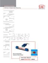
optoCONTROL EDU190
Intended Use
The optoCONTROL EDU190 system is designed for use in industrial and laboratory areas. It is used
to display the measurement values and parameters of all optical optoCONTROL ODC micrometers
with digital interface.
The optoCONTROL EDU190 digital display must only be operated within the limits specified in the
technical data, see operating instructions. The digital display must be used in such a way that no
persons are endangered or machines are damaged in the event of malfunction or total failure of the
system. Take additional precautions for safety and damage prevention in case of safety-related ap-
plications.
Warnings
Avoid use in Ex areas.
> Death or injury due to explosion hazard
Liquids, metal swarf and wire parts may not enter the openings of the digital display under any
circumstances.
> Electric shock, risk of fire
The digital display liquid contains a powerful irritant. In case of skin contact, wash immediately with
plenty of water. In case of eye contact, hold the eye open, flush with plenty of water and get medical
attention.
> Risk of injury, damage to the eyes or skin
Connect the power supply according to the safety regulations for electrical equipment.
> Danger of injury, damage to or destruction of the system
The supply voltage must not exceed the specified limits.
> Damage to or destruction of digital display
No sharp or heavy objects should be allowed to affect the cables. Avoid folding the cables. Do not
bend more tightly than the minimum bending radius of the cables.
> Damage to or destruction of the cables, failure of the digital display
Avoid shocks and impacts to the digital display.
> Damage to or destruction of the digital display
Storing the digital display where the temperature is lower/higher than recommended in the technical
data can cause the LCD display liquid to congeal/become isotopic.
Avoid use in direct sunlight, strong magnetic fields, high temperatures and sudden temperature
changes.
> Color alterations on the display or system failure
X9771398-A011079HDR
MICRO-EPSILON Eltrotec GmbH
Manfred-Wörner-Straße 101 · 73037 Göppingen / Germany
www.micro-epsilon.com
*X9771398-A01*
Notes on CE Marking
The following apply to the digital display:
- EU Directive 2014/30/EU
- EU Directive 2011/65/EU, “RoHS” Category 9
The measuring system is designed for use in industrial environments and meets the require-
ments.
Proper Environment
- Protection class:
Front panel:
:
IP 66 (EDU190-4 Pro), IP 65 (EDU190-7 Pro)
Rear: IP 20
- Operating temperature: -10 ... +60 °C (+14 ... +140 °F)
- Storage temperature: -20 ... +70 °C (-4 ... +158 °F)
- Humidity: 5 - 85% (non-condensing)
- Ambient pressure: Atmospheric pressure
Installation and Assembly
Place the digital display on a stable surface during installation.
Use the cut out dimensions in the technical data, see operating instructions.
Install the digital display into the panel cut-out.
Secure the digital display by screwing the recesses head screw clockwise, allowing the
built-in bracket to flip out and tighten against the cabinet.
Tighten the screws from 0.5 to 1.0 Nm.
4 (or 8) screws
Fig. 1 Installation of digital display
Dimensional drawing for the 4.3 inches model
100 (3.94)*
104 (4.09)
145
(5.71)
43
(1.69)
50
(1.97)*
50
(1.97)*
100 (3.94)*
100 (3.94)*
Cut out dimensions for the installation of the digital display: 130 x 89 mm (5.12 x 3.50 inches)
Fig. 2 Dimensional drawing optoCONTROL EDU190-4 Pro, dimensions in mm (inches), not to scale
Dimensional drawing for the 7 inches model
100
(3.94) *
204
(8.03)
143 (5.63)
43
(1.69)
50
(1.97)*
50
(1.97)*
100
(3.94) *
100
(3.94) *
Cut out dimensions for the installation of the digital display: 189 x 128 mm (7.44 x 5.04 inches)
Fig. 3 Dimensional drawing optoCONTROL EDU190-7 Pro, dimensions in mm (inches), not to scale
*The specified values indicate the space required for installing the control panel.
Displays
A green LED on the right side
of the display indicates if the
transmission is active.
Flashing when the digital display is connected with the
sensor.
No flashing when the digital display is not connected
with the sensor.
The ON/OFF status is dis-
played on the blue multicolor
LED on the left side of the
digital display.
ON
OFF
Compatible Optical Micrometers
The digital display can be used with the following optoCONTROL series:
optoCONTROL 1202
1220
2500
2520
2600
Fig. 4 optoCONTROL EDU190
Read the detailed instruction manual before using the sensor. The manual is available online on
www.micro-epsilon.com/download/manuals/man--optoCONTROL-EDU-190--en.pdf.

Display Measurement Value
1
2
3
4
5
7
6
1 Connection status
2 Measured value - limit values are indicated in colors.
3 Buttons for info window Info and for settings window Cong.
4 LED for connection signal; flushes when connection is active.
5 Type of measurement
6 Triggering switched on
7 Display of limit value status
Sensor Information
1
2
3
1 Selected measuring program
2 Info site about selected sensor type/connection type RS422 or Ethernet
3 Trigger mode state
Connections
Depending on available interfaces, the respective ODC sensors can be connected either via LAN
connection or COM connection.
Power supply
LAN connection COM connection
RS422 / RS232
Item Connection Description
Fig. 5 Ports on the display
bottom side
1 Power supply +24 VDC (18 ... 32 VDC)
2 LAN A 1 x 10/100 Base-T (RJ-45 shielded)
3 COM RS422 or RS232
Please refer to the operating instructions for details on the pin assignment.
Supply voltage:
- Digital display: +24 VDC (18 - 32 VDC)
- The exact values can be found in the operating instructions of the respectively connected
sensor.
Power consumption:
- EDU190-4 Pro: 12 W (24 V)
- EDU190-7 Pro: 14,4 W (24 V)
Cable
PC190-2
Pin Color Power supply
Fig. 6 Pin assignment
PC190-2
PIN + white +24 V
PIN - brown -GND
Switch off the power supply when you exit the display program or switch off the sensor.
Switch on the power supply again when you restart the display program or the sensor.
Connections for optoCONTROL 2500/2600
Ports on the display bottom side Optical connections at the controller of the
ODC 2500/2600
Fig. 7 Connections for optoCONTROL 2500/2600
Connections for optoCONTROL 1202/1220
8-pin. female connector
Binder series 712
(SPS female connector)
4-pin. connector
Binder series 707
(PC female connector)
3-pin. connector
Binder series 712
(connection to sender)
Power supply
COM connection
RS422 / RS232
SCD1202-x-RS232
PC190-2
PS2020
Ports on the display bottom side Connections on the controller of the ODC
1202/1220
Connections for optoCONTROL 2520
Power supply
LAN connection COM connection
RS422 / RS232
PC190-2
SCD2520-3
PC/SC190-3
PS2020
To
light source
CE2520x
PC/SC2520-3/IF2008
Ports on the display bottom side Optical connections at the controller of the
ODC 2520
The Ethernet connection requires the SCD2520-3 and PC190-2 cables.
The RS422 connection requires the PC/SC2520-3/IF2008 and PC/SC190-3 cables.
Software Quick Guide
Settings
The digital display is configured to automatically detect the connected sensor type and to adjust
the user interface accordingly. The display software can be set in English or German and has
several buttons for the visualization, configuration and retrieval of sensor data. Depending on the
sensor, a large number of additional settings such as filters, measuring programs and calculation
functions can be set via the sensor’s web interface and visualized on the display.
It does not matter whether the digital display is connected via the RS232/RS422 connection or the
Ethernet connection.
The set standard IP is 169.254.168.150. Some changes that are selected via the web interface
of the ODC 2520 sensor or the ODC 12xx software will not take effect until the digital display is
restarted.
Disconnect the display from the power supply.
Restart the digital display when you need to change the controller settings.
i
Refer to the operating instructions for the sensor settings.
1
2
4
5
3
1
Master value settings
2
Settings IP address
3
Language setting
4
Circumference calculation from diameter measurement (only selectable with diameter
measurement)
5
Activating limit value measurement and setting upper High limit and lower Low limit
value.
Power supply
LAN connection COM connection
RS422 / RS232
Light source
(5-pin)
Operating voltage
(3-pin)
Receiver
(12-pin)
Inputs and
outputs
(25-pin)
SCD2500-3/EDU190/RS422
SCD2500-3/EDU190/RS232
SCD2500-3-3/RS232
PC190-2
PS2020
/