Page is loading ...

Assembly Manual
Pathway® Stair System
For use with the Pathway® Modular Ramp System, as freestanding stair, or
with other structures.
Manufactured in the USA
LIFETIME WARRANTY. Please register at www.ezaccess.com/warranty-satisfaction.
© EZ-ACCESS®, a division of Homecare Products, Inc. All rights reserved.
All text and images contained in this document are proprietary and may not be shared, modified,
distributed, reproduced, or reused without the express written permission of EZ-ACCESS.
14697 REV 03-03-2020

- 2 -
ASSEMBLY MANUAL
For EZ-ACCESS® Pathway® Stair System
ATTENTION INSTALLER AND END USER:
• For residential use only.
• 850 lb. weight capacity. Do not exceed weight capacity.
• Read and follow all instructions, labels and warnings prior to assembly and use.
• Installer, please leave this ASSEMBLY MANUAL with the end user.
• When Pathway Stair System is freestanding, all four feet of the stair MUST be securely anchored.
TOOLS TYPICALLY REQUIRED:
• Ratchet with 1/2” deep well socket or 1/2” wrench
• 1/8″ drill bit
• 5/32″ T-Handle Allen wrench or similar tool
• 3/16″ Allen wrench
• #2 Phillips head screw driver or similar tool
• Box knife
• 25’ tape measure
• Level
• Rubber mallet
• File
• Power drill
SYMBOL MEANINGS:
This is the WARNING symbol . Symbol may appear in various colors and in conjunction with other symbols.
WARNING may be spelled out and not include the symbol. WARNING (word or symbol) indicates a failure, by any
user, to obey that safety warning could result in damage to property and or equipment, as well as serious personal
injury or death to operator and others.
This is the NOTE symbol . Symbol may appear in various colors and in conjunction with other symbols. NOTE
may be spelled out and not include the symbol. NOTE (word or symbol) indicates a failure to obey all notes could
result in improper operation, and, at the sole discretion of the manufacturer, may void your warranty.
WARNING! READ AND FOLLOW ALL INSTRUCTIONS AND WARNINGS BEFORE USE!

- 3 -
PROPER SET UP AND USE WARNINGS
• Read and follow all labels, instructions, and warnings prior to assembly and use. To obtain a copy of
complete instructions and warnings, call customer service at 1-800-451-1903.
• Whenever the Pathway Stair System is freestanding, all four feet of the stair MUST BE securely anchored.
• Use caution at all times. Proper maintenance and upkeep to the stair system and all Pathway® system
components is vital. NOTE: The term “system” refers to the entire Pathway Modular Access System,
including, gate, stairs, ramp, platform, risers, handrails, supports, transition plates, landing pad, and any/all
hardware and components.
• Regularly check that all parts are in good condition and check the system for damage. Ensure all fasteners
and locking mechanisms are in place and tightened. If any part of the stair system is damaged, loose, or
missing, DO NOT USE UNTIL REPAIRS CAN BE MADE BY A CERTIFIED INSTALLER OR OTHER
QUALIFIED PERSON.
• Do not walk, sit, stand, etc. on the system until the installation is complete.
• Consult local building codes regarding securing stair system for wind loads.
• If user has a mobility concern, or is otherwise not in able-bodied physical condition, ONLY USE STAIR
SYSTEM WITH A QUALIFIED HELPER.
• Keep the stair system clear of debris and clutter. Do not use if walking surface is unsafe.
• The system may be slippery when wet or icy.
• Confirm the stair system is correctly leveled and positioned securely. Periodically check for ground shifts.
• Metal conducts electricity. Do not use near exposed wiring or hang lights from stair system.
• Never place anything on, under, or attach anything to system.
• Only use components supplied or approved by manufacturer with system.
• Do not sit, stand, or climb on guards, gates, or handrails.
• Do not use handrails, gates, or any other part of the stair system, to support planters, decorations, etc.
• Do not play on or around stair system, including, but not limited to, running, jumping, bicycles, scooters,
skateboards, etc.
• Properly support and restrain stair system in transit or storage.
• At all times, keep the stair system clear of dirt, leaves, and other debris that may accumulate on the
surface. Simply sweeping the system or using a garden hose will usually suffice, but, if needed, a damp
cloth or soft brush with soap and water can be used (avoid alkaloid detergents). Rinse well and use extra
caution when stair system surface is wet.
• If system surface is covered with ice and/or snow, DO NOT USE until accumulation is removed and the
tread surface swept clean. Magnesium Chloride salt substitute may be used to melt snow or ice
accumulation. However, after the snow and/or ice threat has cleared, be sure to clean the tread surface
with soap and water (avoid alkaloid detergents) to remove Magnesium Chloride residue. Rinse well and
use extra caution when stair system surface is wet.
• Regularly check that all parts are in good condition and check the stair system for damage. Ensure all
fasteners and locking mechanisms are in place and tightened. If any part of the system is damaged, loose,
or missing, DO NOT USE UNTIL REPAIRS CAN BE MADE BY A CERTIFIED INSTALLER OR OTHER
QUALIFIED PERSON.
• If stair system is damaged or unstable, DO NOT USE UNTIL REPAIRS CAN BE MADE BY A CERTIFIED
INSTALLER OR OTHER QUALIFIED PERSON.
• For additional care, usage, or general safety information, please call 1-800-451-1903.

- 4 -
The Pathway Modular Stair System is designed to work in conjunction with the Pathway Modular Ramp System but
can be used as a standalone stair on an existing porch or deck. There are seven models which cover different
height ranges from 8” to 59-3/8”. See below for descriptions and height ranges. Each stair will include two side rails,
two legs, the number of treads needed for the height range and posts, handrail tubes and tube connectors.
USAGE NOTES:
When properly anchored, the Pathway Modular Stair System may be used as a freestanding stair.
The Pathway Modular Stair System may also be attached to existing platforms, decks, or other suitable structures.
INSTALLATION/CONFIGURATION WARNING:
Installing the Pathway Stair System in any non-compliant configuration, or rise, may result in an unsafe situation and
or installation being rejected by your local inspector or AHJ. Always check your local codes and assemble in
compliance. Consult your local contractor for assistance.
CONFIGURATIONS CHART ( SEE “INSTALLATION/CONFIGURATION WARNING” ABOVE)
PN Short Name Description (w/ Recommended Rises)
Number
of Treads
Rise: Code
Compliant
Rise: Non-
Compliant
14911 PSS0814 EZ-ACCESS PATHWAY STAIR SYSTEM 8”-14" 1 8”-14” 8”-17.375”
14912 PSS1521 EZ-ACCESS PATHWAY STAIR SYSTEM 15”-21" 2 15”-21” 15”-24.375”
14913 PSS2228 EZ-ACCESS PATHWAY STAIR SYSTEM 22”-28" 3 22”-28” 22”-31.375”
14914 PSS2935 EZ-ACCESS PATHWAY STAIR SYSTEM 29”-35" 4 29”-35” 29”-38.375”
14915 PSS3642 EZ-ACCESS PATHWAY STAIR SYSTEM 36”-42" 5 36”- 42” 36”- 45.375”
14916 PSS4349 EZ-ACCESS PATHWAY STAIR SYSTEM 43”-49" 6 43”-49” 43”-52.375”
14917 PSS5056 EZ-ACCESS PATHWAY STAIR SYSTEM 50”-56" 7 50”-56” 50”-59.375”
When connected to a platform in the Pathway Modular Ramp System, the stair will commonly be used with at least
one Platform Handrail to Stair Connector (MHRPSC).

- 5 -
Refer to the Pathway Modular Ramp System assembly manual for all instructions not covered in this manual for
the Pathway Stair System.
1. BASIC SYSTEM COMPONENTS
1.1. Because each installation is different, your system may or may not contain these basic
components.
PATHWAY STAIR SYSTEM
Pathway Stair System 22”-28” (shown without stair support tubes and feet).
OPTIONAL: MHRPSC
(CONNECTOR – HR PLATFORM TO HR STAIR)
OPTIONAL: PSSxxxx
FEET & LEG PAIRS
This kit is used to connect the stair handrails to the
platform handrails. The supplied 36” handrail tubes
are cut to length during installation.
This kit is used for additional support at the top of
the stair system or when stairs are being used as
a standalone system.
NOT TO SCALE

- 6 -
2. ASSEMBLING THE RISER
2.1. Lay the right hand stair side rails flat with tread channel cleats pointing up and insert the treads
into the channel cleats. Place on cardboard or other suitable surface to avoid scratching the side
rail. Make sure the tread is positioned with the traction ridges oriented upward. Use a rubber mallet
if needed to tap the tread into the tread channel cleat until the holes in the cleat line up with the
holes in the stair tread (FIG.1).
FIG. 1
2.2. Install 5/16”-18 x 2-1/4” carriage bolts in the holes through the top side of the right hand channel
cleats. Use a rubber mallet to sink carriage bolts into holes. Install 5/16” washers and nuts onto the
carriage bolts on the bottom side of the channel cleats but do not tighten fully yet (FIG. 2).
FIG. 2

- 7 -
2.3. Set the left hand side rail on the treads and tap into place until the holes in the channel cleat line
up with the holes in the tread (FIG.3).
FIG. 3
2.4. Install 5/16”-18 x 2-1/4” carriage bolts with nuts and washers in the left side rail and through the
tread, as described in 2.2.
2.5. After all carriage bolts, nuts and washers are installed, tighten nuts using ratchet with 1/2” socket
or 1/2” wrench. Tighten nuts until the channel cleat clamps onto the tread slightly. NOTE: Some
deformation in the channel cleat by the carriage bolt is normal.
3. ASSEMBLING THE STAIR LEGS & HANDRAILS
3.1. First assemble the stair hangers to the top vertical posts. The top vertical post is the post with six
3/8” holes; the bottom vertical post only has four. Attach the stair hangers to the hole 10” from the
bottom using the 5/16”-18 x 3/4” long hex bolt, 5/16”-18 locknut and 5/16” flat washer supplied.
Orient the Stair Hanger as shown with the short leg attached to the post and the long leg oriented
toward the bottom then tighten fasteners securely (FIG.4).
NOTE: The top vertical posts are universal but stair hangers must be assembled to opposite sides
to create posts for the left and right side of the stairs.
FIG. 4

- 8 -
3.2. Insert the top vertical posts into each top corner pocket with the stair hanger oriented away from
the riser. Tighten one 3/8”-16 set screw in each top corner pocket (FIG.5).
3.3. Insert legs in bottom corner pockets so that the square base foot is oriented under the riser as
shown. Tighten one 3/8”-16 set screw on each bottom corner pocket (FIG. 6).
FIG. 5
FIG. 6
3.4. Hang the stair assembly on the platform in the desired location. Adjust the vertical position of the
riser on the legs and top posts by loosening and retightening the 3/8”-16 set screws in the riser
corner pockets until the distance from bottom tread to ground is approximately the same distance
from top tread to the platform walking surface and the stair treads are level. After the riser has
been positioned and leveled, tighten all set screws in the corner pockets for stair top posts and
legs securely (FIG. 7).

- 9 -
FIG. 7
3.5. Make sure the stair assembly is positioned flush against the platform side rail and use the holes in
the stair hanger tabs as a template to drill 1/8” holes through the top wall of the side rail. Fasten
the stair assembly to platform using two provided 1/4" pan head self-tapping screws (FIG. 8).
NOTE: If the stair will be used with a Connector – HR Platform to Stair (MHRPSC), a minimum of
6” is required between the platform vertical post and stair top post.
FIG. 8
3.6. Insert the stair bottom posts in bottom corner pockets with the holes on top (FIG. 9). DO NOT
tighten set screws yet.

- 10 -
FIG. 9
3.7. Locate the eight closure elbows and disassemble by removing the screw and nut, then remove the
center insert (FIG. 10).
3.8. Insert the elbow half with the internal set screw into both ends of one handrail tube. Make sure the
side for the assembly screw is oriented in the same direction and the flat portions of the elbow
halves are parallel on both ends of the handrail tube then tighten the internal set screw securely
using a T-Handle Allen wrench or similar tool. NOTE: The handrail tubes need to be trimmed most of
the time. It is recommended you complete steps 3.10 to 3.12 with one handrail tube before installing
elbow halves with internal set screws in the rest.
FIG. 10

- 11 -
3.9. Assemble the closure elbow halves with threaded holes to the stair posts on the side facing the
riser using the provided 5/16”-18 x 3/4” long hex bolts but do not tighten fully (FIG. 11).
3.10. Using one handrail tube with closure elbow halves with internal set screws installed, assemble to
one of the closure elbow halves with the threaded hole in stair upper post using the elbow center
insert, assembly screw & nut but do not tighten fully (FIG. 12).
3.11. Adjust stair bottom post on one side up or down until the handrail tube is parallel to the stair side
rail and the holes in the elbow halves at the stair bottom post align then tighten the
3/8”-16 set screws in the bottom corner pockets securely (FIG. 12). NOTE: If the holes in the
elbow halves at the stair bottom post do not align when the handrail tube is parallel to the stair side
rail, the handrail tube must be trimmed until they do. Remove the elbow half with the internal set
screw from the from the lower end of the handrail tube, trim as needed & reinstall elbow half.
Repeat until tube is parallel to stair side rail and holes in lower elbow align.
3.12. After one of the stair bottom posts is set at the correct height, set the other at the same height and
tighten the set screws in the bottom corner pockets securely.
3.13. Cut the remaining handrail tubes to the final length established in 3.11 and insert closure elbow
halves with internal set screws as described in 3.8.
3.14. Assemble the handrail tubes with closure elbow halves with internal set screws installed to the
elbow halves installed on the stair posts in 3.9 and tighten all elbow assembly and elbow
attachment bolts securely.
3.15. Insert a 1-1/2” square tube plug into the top of each leg and install a plastic angle cap on top of
each stair post (FIG. 13). Use the Turbo Fuse Gel included with the stair assembly hardware to
secure the plastic angle caps as needed.
3.16. The stair legs of the Pathway Stair System must be anchored (anchors not provided) to the
ground. Select the appropriate anchor for the ground condition where the stair is installed and use
the holes closest to the front of the stair for anchoring (FIG. 11).
FIG. 11

- 12 -
FIG. 12
FIG. 13

- 13 -
4. INSTALLING THE CONNECTOR – HR PLATFORM TO HR STAIR (MHRPSC)
(OPTIONAL EQUIPMENT)
4.1. Installation of the closure elbows in the CONNECTOR – HR PLATFORM TO HR STAIR
(MHRPSC), used to connect a stair top post to a platform handrail post, is similar to installing the
stair handrails but the closure elbow is not disassembled first. Assemble one closure elbow to the
stair top post and one to the platform handrail post opposite the stair top post using the provided
5/16”-18 x 3/4” long hex bolts but do not tighten fully (FIG. 14).
FIG. 14
4.2. The closure elbow attached to the stair top post should be at approximately 90 degrees and
pointed toward the closure elbow attached to the platform handrail post. Align the round portions of
the closure elbows facing each other and make sure the flat faces are parallel then tighten the
5/16”-18 x 3/4” long hex bolts and the elbow assembly screws enough to hold the elbows in place.
4.3. Measure the distance between the two larger round faces. The gap between the upper and lower
closure elbows should be the same but it is advisable to check both before cutting the tubes to fit
(FIG.15).
FIG. 15

- 14 -
4.4. Cut the 1-1/2″ diameter round tubes to fit the gap measured in the previous step.
4.5. Using a metal file, smooth all sharp edges from cutting the round tubes.
4.6. Disassemble the closure elbows by removing the elbow screws and nuts but do not remove the
closure elbows halves from the platform handrail or stair top posts (refer to FIG. 10 for closure
elbow assembly details).
4.7. Install a closure elbow half with internal set screw into each end of the cut tube until fully engaged.
4.8. Test fit assembly with closure elbow halves installed on the posts then remove and tighten internal
set screws with a T-Handle wrench. An Allen wrench and pliers to get additional torque can be
used as an alternate.
4.9. Reassemble all elbows by replacing center insert and securing with the screw and nut then tighten
all fasteners, including the 5/16”-18 x 3/4” long hex bolts, securely.
4.10. Test to ensure all elbows are properly secured and attached. If needed, tighten internal set screws
to secure more rigidly.
4.11. Repeat steps 4.1 to 4.10 for all locations.
4.12. Double check that all fasteners are tightened securely. Periodically check for ground shifts and
regularly check and tighten hardware as needed.
5. INSTALLING FEET AND PATHWAY SYSTEM LEG PAIRS (PSSxxxx) (OPTIONAL
EQUIPMENT)
5.1. Installation of PATHWAY STAIR SYSTEM LEG PAIRS (PSSxxxx where xxxx denotes the stair
system rise) at the top is similar to installing the stair leg at the bottom but the components are not
welded assemblies. First insert the 1-1/2” square support tube through the open area in the upper
riser corner pocket and into the foot. The foot should be oriented either under the stair as shown
(FIG. 16).
FIG. 16

- 15 -
5.2. Tighten the thumb screw in the foot.
5.3. Use the hole in the foot as a template to drill an 11/32” or 3/8” hole through the support tube and
secure foot to support tube using a 5/16”-18 x 3” long hex bolt & 5/16”-18 locknut.
WARNING! YOU MUST INSTALL THE NUT AND BOLT LISTED IN STEP 5.3 ABOVE, OR A
DANGEROUS SITUATION MAY RESULT.
5.4. Tighten the 3/8”-16 set screws in the riser corner pocket securely (FIG.16).
5.5. Insert a 1-1/2” square tube plug into the top of each support tube.
5.6. Repeat steps 5.1 to 5.5 on the opposite side.
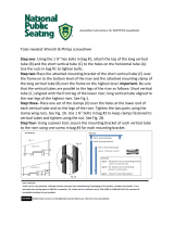
6. FREESTANDING STAIR USE & INSTALLATION
WARNING! WHEN USING AS A FREESTANDING STAIR, YOU MUST SECURELY ANCHOR
ALL FOUR FEET, OR A DANGEROUS SITUATION MAY RESULT. CONTACT YOUR LOCAL
CONTRACTOR FOR EXPERT ADVICE AND ASSISTANCE.
6.1. If the Pathway Stair System is freestanding (i.e., not attached to a platform, deck, or porch) ALL
FOUR FEET (TWO AT THE BOTTOM AND TWO AT THE TOP) OF THE STAIR MUST BE
SECURELY ANCHORED (anchors not provided). Select the appropriate anchor for the ground
condition where the stair is installed. Use the holes closest to the front of the stair for the two
bottom feet and any one of the three holes in the two polymer feet at the top (FIG. 17).
FIG. 17
/