Page is loading ...

Manufactured in the USA
3-YEAR WARRANTY. Please register at www.ezaccess.com/warranty-satisfaction.
© EZ-ACCESS®, a division of Homecare Products, Inc. All rights reserved.
All text and images contained in this document are proprietary and may not be shared, modified, distributed,
reproduced, or reused without the express written permission of EZ-ACCESS.
18543 02-28-2020
PATHWAY® HD Code Compliant Modular Access System
Installation Supplement for PATHWAY® HD Steps
Use this Supplement alongside the PATHWAY® HD Code Compliant Modular Access System Installation Manual

IN
Installation Supplement for PATHWAY® HD Steps
Page 2 of 29
INTRODUCTION
This supplement addresses the installation of PATHWAY® HD Steps, a component that attaches to the PATHWAY®
HD Code Compliant Modular Access System but can also be installed on most existing landings. Refer to the
PATHWAY® HD Code Compliant Modular Access System Installation Manual for instructions relevant to ramps,
platforms, and their related components. Throughout this document, the PATHWAY HD Steps are also referred to as
“step”, “steps”, and “system”. For more information, please call customer service at 1-800-451-1903.
SYMBOL MEANINGS
The WARNING symbol indicates a potentially hazardous condition/situation. The safety warnings
throughout this manual, and on your equipment, if any, are for the protection of people and property.
Failure by any operator to abide by safety warnings will result in a waiver of all liabilities, loss of your
warranty, and could result in equipment damage and or failure, property damage, risk of serious bodily
injury, and or death. The symbol may appear in various colors and in conjunction with other symbols
and with or without the written word “WARNING”.
The NOTE symbol indicates important information. Failure to obey all notes could result in improper
operation, less-than-optimum equipment performance, and at the sole discretion of the equipment
manufacturer, may void your warranty. The symbol may appear in various colors and in conjunction
with other symbols and with or without the written word “NOTE”.
WARNINGS
STAIR Uniform Live Load Rating: 100 pounds per square foot and a concentrated vertical load of 300
pounds over an area of 4 square inches. Do not exceed Uniform Live Load Rating.
PLATFORM Rated Load: 100 lbs. psf live load, 300 lbs. concentrated. Do not exceed Rated Load.
Read, understand, and follow the Installation Manual, Supplements, and Addendums, if any, in their
entirety. Learn and understand the location and function of all features, Rated Load, safety devices,
and labels before use. If you do not understand which manuals apply, or their content, do not use the
system and call 1-800-451-1903 for further information.
Always follow all warnings and safety directives.
Maintaining all labels and manuals in legible condition is required by the system owner and is
essential for safe operation. Do not remove product safety labels. If any labels are missing,
damaged, or become illegible, they must be replaced. An illegible label will fail to alert individuals on
or around the system of a procedure or hazardous operating conditions. To obtain replacement
copies of instructions, warnings, and labels, call 1-800-451-1903.
Professional installation by an EZ-ACCESS approved technician is required.
Do not use the system for anything other than its intended purpose of providing access to individuals
moving from one landing to another.
Always use handrails for added stability.
Use only components supplied or approved by EZ ACCESS with the system.
Never place on, under, or attach to the system anything the manufacturer did not supply. Do not use
any part of the system to support, attach, or hang planters, baskets, lights, ropes, cords, decoration,
fabrics, or other ornaments or furnishings.
Proper maintenance and upkeep to the system is vital. Call 1-800-451-1903 to inquire about inspections
and service.
Before each use, visually inspect the system to ensure that all parts are in good condition and that
the system is free of any damage. If any part of the system appears damaged, loose, or missing, do
not use until repaired by an EZ ACCESS approved technician.
Annually (more frequent in harsher environments) inspect all fasteners and verify all nuts, bolts,
screws, and other fasteners are undamaged and secure. If any part of the system appears damaged,
loose, or missing, DO NOT USE until repaired by an EZ ACCESS approved technician.
Do not tamper with, attempt to repair, or modify any portion of the system. Only EZ-ACCESS
approved technicians may provide service.
The system must be installed and maintained as specified in this manual and per your applicable
local codes. Ask your local contractor or your Authority Having Jurisdiction (AHJ) for information.

IN
Installation Supplement for PATHWAY® HD Steps
Page 3 of 29
WARNINGS, CONT’D.
This system is made from aluminum. Aluminum is electrically conductive. Do not lay power cords on or
across electrically conductive materials, such as this system. Do not use system near exposed wiring or
hang lights or extension cords from system.
Use caution when using the system. Ensure hair, clothing, shoelaces, jewelry, and other personal
items are not and do not catch on anything that may create a hazard.
Do not lean on, walk on, or otherwise bear weight on the system until installation is complete.
Use system only with a qualified helper.
Before each use, remove dirt, leaves, and all other items and debris that may have accumulated.
Sweeping will often suffice, but for more concentrated cleaning, use a garden hose and a damp
cloth or soft brush with mild soap and water (avoid alkaline detergents). Rinse well and use extra
caution when system surface is wet.
If snow and or ice is present on the system, remove accumulations before use. Please refer to
‘DEICING’ section for more information.
Before each use, confirm the system is level and positioned securely. Periodically check for ground
shifts and make any necessary adjustments.
Do not sit, stand, or climb on guards, gates, or handrails.
Only walk on the step. Never play, run, jump, or climb, on or around.
Properly support and restrain the system in transit or storage.
For additional care, usage, or general safety information, please call 1-800-451-1903.
ATTENTION INSTALLER and END USER
Prior to use, read and understand this manual and all other applicable manuals, including
supplements and addendums, if any, and warning labels, in their entirety. Learn and understand the
location and function of all features, Rated Loads, safety devices, and labels before use. If you do
not understand which manuals apply, or their content, do not use the PATHWAY® HD Code
Compliant Modular Access System and call 1-800-451-1903 for further information.
Leave this Installation Manual with the end user.
Fill out online warranty registration.
IMPORTANT SHIPPING INFORMATION
The shipment contains a packing list. Confirm all items are present before starting installation. Open
shipping boxes and inspect for damage or missing parts. If damaged or missing parts are noted, DO
NOT INSTALL OR USE.
Check for shipping damage immediately upon receipt and note any freight damage on freight bill
while driver is still present. Contact shipper right away with any freight damage concerns. In most
cases, freight damage claims will not be allowed unless noted on the freight bill. Pictures of damage
before the unit is unpacked can be very helpful.
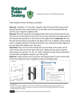
TOOLS TYPICALLY REQUIRED
POWER DRILL
TORPEDO OR CARPENTER’S LEVEL
PLIERS
7/16″ SOCKET OR 7/16″ WRENCH
#2 PHILLIPS HEAD SCREWDRIVER
HACKSAW
1/2″ SOCKET OR 1/2″ WRENCH
1/8”, 3/8”, AND 13/32” DRILL BITS
C-CLAMPS
5/16″ SOCKET OR 5/16″ WRENCH
5/32″ AND 3/16″ ALLEN WRENCHES
BOX KNIFE
RAT TAIL AND FLAT FILE
25’ TAPE MEASURE
RUBBER MALLET

IN
Installation Supplement for PATHWAY® HD Steps
Page 4 of 29
TABLE OF CONTENTS
SECTION 1: GETTING STARTED ........................................................................................................................... 5-6
SECTION 2: TWO-LINE RAIL CLOSURE ................................................................................................................. 7-8
SECTION 3: PICKETED GUARD CLOSURE ........................................................................................................... 9-10
SECTION 4: STEP HANDRAILS .......................................................................................................................... 11-14
SECTION 5: 60” RISE STEP GUARD REINFORCEMENT ..................................................................................... 15-16
SECTION 6: RETURNING HANDRAIL AT CLOSURE ........................................................................................... 17-18
SECTION 7: UPPER LOOP ................................................................................................................................. 19-20
SECTION 8: CONNECT STEP HANDRAIL TO RAMP HANDRAIL ......................................................................... 21-22
SECTION 9: OPTIONAL EQUIPMENT – RETURN TO GROUND HANDRAIL ....................................................... 22-23
SECTION 10: OPTIONAL EQUIPMENT – RETURN TO LANDING HANDRAIL ..................................................... 24-27
SECTION 11: OPTIONAL EQUIPMENT – STEPS ON PLATFORM EXTENDER ...........................................................28
SECTION 12: LEVELING FEET .................................................................................................................................28
SECTION 13: FINAL STEPS AND CHECKS ................................................................................................................29
SECTION 14: DEICING ............................................................................................................................................29

IN
Installation Supplement for PATHWAY® HD Steps
Page 5 of 29
1. GETTING STARTED
1.1. Before beginning the assembly process, install the PATHWAY® HD Code Compliant Modular Access
System, except DO NOT install a platform guard or two-line rail on the side of a platform where the
step will be installed.
When a step is installed on the 5’ side of a platform, center the step on the platform and use
upper loops on both sides of the step. When installed on wider platforms, place the step to one
side of the platform and use a upper loop only on the side closest to the platform angle post
and use a closure on the other side. For placement in any other location on a platform, custom
components may be required.
The platform to which the step attaches to must be stable and level.
The surface on which the step rests must also be stable and level. If ground is not stable
and level, create a surface that is stable and level at the proper height by digging or filling.
Leveling feet come with the system. When adjusting the step, be mindful of applicable building
codes and ADA guidelines. EZ-ACCESS will not be responsible for any costs or liabilities resulting
from use of the leveling feet. The ground must be leveled at the proper height with respect to
the platform.
1.2. There are three common configurations for step use (FIG. 1.1). For situations other than those
shown, consult the project drawings for the specific arrangement.
1.2.1. Adjacent to ramp at 90° (an “inside” corner turn).
1.2.2. In-line on the opposite side of a ramp.
1.2.3. On a landing platform without a ramp (standalone).
Never place a step directly across from a down sloping ramp without a gate or
other device to prevent the person descending the ramp from unintentionally
continuing forward down the steps.
FIG. 1.1

IN
Installation Supplement for PATHWAY® HD Steps
Page 6 of 29
1.3. Set the upper lip of the riser onto the platform in the desired location (FIG. 1.2).
Do not lean, walk, or otherwise bear weight on the step until installation is complete.
1.4. Install two step guards into the corner pockets of the step until the lower post rests on the ground or
aligns with the bottom of the lower corner pockets (FIG. 1.2).
1.5. Tighten two 3/8”-16 x 1/2” long headless cup point socket setscrews in each corner pocket securely
(FIG. 1.2).
1.6. Install 1-1/2” square x 3/16” wall tube plugs in the tops of the 1-1/2” step guard posts. Use a rubber
mallet or similar tool to fully seat as needed (FIG. 1.2).
1.7. If installing a step on the 5-ft. (nominal) side of a PATHWAY HD platform, skip to ‘STEP HANDRAILS’
section.
FIG. 1.2

IN
Installation Supplement for PATHWAY® HD Steps
Page 7 of 29
2. TWO-LINE RAIL CLOSURE
2.1. Install a platform angle post in the open corner pocket where the two-line rail will be attached
(FIG. 2.1). Secure in place as described in the ‘HANDRAILS’ section of the PATHWAY HD Code
Compliant Modular Access System Installation Manual.
2.2. Insert 1-1/2” diameter 5/16”-18 threaded inserts in both ends of the 1-1/2” diameter top rail and
1-1/2” square 5/16”-18 threaded inserts in both ends of the midrail and barrier. Use a rubber
mallet or similar tool to fully seat as needed (FIG. 2.1).
The top rail, midrail, and barrier are specific to the platform size and should not require trimming.
2.3. Connect the top rail, midrail, and barrier to the platform angle post using 5/16”-18 x 1” hex bolts
and 5/16” flat washers in the locations shown (FIG. 2.1).
Do not use a washer with the lowermost bolt.
FIG. 2.1

IN
Installation Supplement for PATHWAY® HD Steps
Page 8 of 29
2.4. Attach 1-1/2” square closure post to the top rail and midrail using a 5/16”-18 x 2-1/4” hex bolt and
5/16” flat washer. Do not tighten fully at this time (FIG. 2.2).
2.5. Attach the upper closure bracket to the 1-1/2” square closure post using a 5/16”-18 x 2-1/4” hex
bolt, 5/16”-18 locknut, and 5/16” flat washer through the second hole from the top. Do not tighten
fully at this time. Orient the bracket as shown with respect to the closure post and the upper step
guard post (FIG. 2.2).
2.6. Attach lower closure bracket to the 1-1/2” square closure post and barrier using 5/16”-18 x 2-
1/4” hex bolt and 5/16” flat washer through the post and bracket into the threaded inserts in the
barrier. Orient the bracket as shown with respect to the closure post and the upper step guard
post (FIG. 2.2).
2.7. Attach the two closure brackets to the upper step guard post using 5/16”-18 x 2-1/4” hex bolts,
5/16”-18 locknuts, and 5/16” flat washers (FIG. 2.3).
2.8. Install a 1-1/2” square tube plug in the top of the 1-1/2” square closure post. Use a rubber mallet
or similar tool to fully seat as needed (FIG. 2.4).
2.9. Tighten all fasteners securely.
FIG. 2.2
FIG. 2.3
FIG. 2.4

IN
Installation Supplement for PATHWAY® HD Steps
Page 9 of 29
3. PICKETED GUARD CLOSURE
3.1. Install a platform angle post in the open corner pocket where the picketed guard closure will be
attached (FIG. 3.1).
3.1.1. Secure in place as described in the ‘HANDRAILS’ section of the PATHWAY HD Code
Compliant Modular Access System Installation Manual.
3.2. Insert 1-1/2” diameter 5/16”-18 threaded inserts in both ends of the 1-1/2” diameter top rail. Use
a rubber mallet or similar tool to fully seat as needed (FIG. 3.1).
The top rail and picketed guard closure are specific to the platform size. Because the
picketed guard closure is symmetric, it can be installed with either end up.
3.3. Connect the top rail and picketed guard closure to the platform angle post using 5/16”-18 x 1” hex
bolts and 5/16” flat washers in the locations shown (FIG. 3.1).
Do not use a washer with the lowermost bolt (FIG. 3.1).
3.4. Attach the 1-1/2” square closure post to the top rail using a 5/16”-18 x 2-1/4” hex bolt and 5/16”
flat washer. Do not tighten fully at this time (FIG. 3.2).
3.5. Attach closure brackets to the 1-1/2” square closure post and to the picketed guard closure using
5/16”-18 x 2-1/4” hex bolts and 5/16” flat washers through the post and closure brackets, into the
threaded inserts in the picketed guard closure top and bottom rails. Do not tighten fully at this time
(FIG. 3.2).
FIG. 3.1
FIG. 3.2

IN
Installation Supplement for PATHWAY® HD Steps
Page 10 of 29
3.6. Attach two closure brackets to the upper step guard post using 5/16”-18 x 2-1/4” hex bolts,
5/16”-18 locknuts, and 5/16” flat washers (FIG. 3.3).
3.7. Install a 1-1/2” square tube plug in the top of the 1-1/2” square closure post. Use a rubber
mallet or similar tool to fully seat as needed (FIG. 3.4).
3.8. Tighten all fasteners securely.
FIG. 3.3
FIG. 3.4

IN
Installation Supplement for PATHWAY® HD Steps
Page 11 of 29
4. STEP HANDRAILS
4.1. This section discusses the various loops and handrail components that are available for the step.
FIG. 4.1a Lower Loop Left Hand
FIG. 4.1b Lower Loop Right Hand
FIG. 4.1c Extended Lower Loop Left Hand
Extended lower loops are intended for use in localities where code requires the
lower loop to extend 12” level in addition to the one tread depth at the slope of
the step
FIG. 4.1d Extended Lower Loop Right Hand
FIG. 4.1e Upper Transition Bend Left Hand
FIG. 4.1f Upper Transition Bend Right Hand
FIG. 4.1g Upper Loop
FIG. 4.1h 90° Bend is available in 13-1/4”, 26-1/2”, and 38-3/4” lengths (field-trim as needed)
FIG. 4.1i 1-1/2” Diameter Handrail (field-trim to length)
FIG. 4.1j Center Handrail Bracket Pair (used on steps 42” and higher only)
LOWER LOOP – LEFT LOWER LOOP – RIGHT
EXTENDED
LOWER LOOP – LEFT
EXTENDED
LOWER LOOP – RIGHT
FIG. 4.1a
FIG. 4.1b
FIG. 4.1c
FIG. 4.1d
UPPER TRANSITION BEND – LEFT UPPER TRANSITION BEND – RIGHT UPPER LOOP
FIG. 4.1e
FIG. 4.1f
FIG. 4.1g
90° BEND HANDRAIL CENTER HANDRAIL BRACKET (PAIR)
FIG. 4.1h
FIG. 4.1i
FIG. 4.1j

IN
Installation Supplement for PATHWAY® HD Steps
Page 12 of 29
4.2. Attach lower loops to lower step guard posts and 1-1/2” square pickets using 5/16”-18 x 2-1/4”
button head socket cap screws, 5/16”-18 locknuts, and 5/16” flat washers oriented as shown. Do
not tighten fully at this time (FIG. 4.2).
4.3. Attach (or clamp securely in the correct location) the top transition bends to the upper 1/2” square
pickets using 5/16”-18 x 2-1/4” button head socket cap screws, 5/16”-18 locknuts, and 5/16” flat
washers oriented as shown (FIG. 4.2). Do not tighten fully at this time.
4.4. The handrail comes in a length which may cover two or more riser heights. Orient the swaged end
toward the top transition bend, then trim the non-swaged end until the handrail fits snugly between the
lower loop and the top transition bend with the swaged end extending into the top transition bend as
far as possible and the swaged end of the lower loop extending as far as possible into the non-swaged
end of the handrail. This may require removing and reinstalling the top transition bend more than once
for the best fit (FIG. 4.3).
4.4.1. Use a file to deburr all sharp edges from trimming handrail.
4.5. Securely tighten the fasteners attaching the lower loop and top transition bend.
FIG. 4.2
FIG. 4.3

IN
Installation Supplement for PATHWAY® HD Steps
Page 13 of 29
4.6. Drill two 1/8” pilot holes:
4.6.1. One on the underside of the handrail.
4.6.2. One on the underside of the top transition bend at 3/4” from the non-swaged ends,
through one wall of the handrail or top transition bend and the swaged ends where they
overlap (FIG. 4.4).
4.7. Install 1/4” x 1” self-drilling, self-tapping pan head Phillips screw through each pilot hole (FIG. 4.4).
4.8. Attach the lower loop return tab to the lower 1-1/2” square picket using a 5/16”-18 x 1-1/4” long hex
washer head screw (FIG. 4.5).
4.9. Tighten all fasteners securely.
4.10. Repeat the same process for installing the handrail on the opposite side of the step.
4.11. If the installation includes a step that is 42” or higher, the guards will include a center 1-1/2” square
picket and come with a pair of center handrail brackets. Steps below 42” high generally do not have
a 1-1/2” square center picket. If the 1-1/2” square center picket is not included, then center handrail
brackets are not required.
For center handrail brackets on a 60” step rise, refer to ‘60” RISE STEP GUARD
REINFORCEMENT’ section.
FIG. 4.4
FIG. 4.5

IN
Installation Supplement for PATHWAY® HD Steps
Page 14 of 29
4.12. Attach center handrail brackets to center 1-1/2” square pickets using 5/16”-18 x 2-1/4” button head
socket cap screws, 5/16”-18 locknuts, and 5/16” flat washers oriented as shown (FIG. 4.6). Tighten
securely.
4.13. Attach center handrail bracket to the step handrail using a 1/4” x 1” long self-drilling, self-tapping
pan head Phillips screw (FIG. 4.7).
4.14. Tighten all fasteners securely.
4.15. Repeat the process for installing the center handrail bracket on the opposite side of the step.
4.16. If installing a step on the 5-ft (nominal) side of a PATHWAY HD platform, skip to ‘RETURNING
HANDRAIL AT CLOSURE’ section.
FIG. 4.6
FIG. 4.7

IN
Installation Supplement for PATHWAY® HD Steps
Page 15 of 29
5. 60” RISE STEP GUARD REINFORCEMENT
5.1. The 60” step includes two 1-1/2” square step guard reinforcement posts (“reinforcement posts”)
and the required hardware to reinforce the guards at the center 1-1/2” square pickets.
5.2. Install the center handrail brackets and the reinforcement posts to the center 1-1/2” square pickets
using 5/16”-18 x 4” button head socket cap screws, 5/16”-18 locknuts, and 5/16” flat washers,
oriented as shown (FIG. 5.1).
5.2.1. Orient the reinforcement posts so that the two lower holes at 7-1/4” apart are in contact
with the side rail (FIG. 5.1). Do not fully tighten at this time.
The lower hole should be approximately 1-1/8” vertically from the bottom of
the side rail when the upper hole is aligned with the center handrail bracket
mounting hole. If the two lower holes in the reinforcement post are not
positioned so they can be used as a template to drill holes in the riser side
rail, or the second hole from the bottom is not on the side rail, the post is
upside down. Flip 180-degrees and reassemble in the correct orientation.
5.3. Using the reinforcement post as a template, drill three 3/8” holes through both the center 1-1/2”
square picket and the side rail (FIG. 5.1). Rotate the 1-1/2” square reinforcement posts out of the
way or disassemble if needed.
FIG. 5.1

IN
Installation Supplement for PATHWAY® HD Steps
Page 16 of 29
5.4. Attach reinforcement post to riser side rail using 5/16”-18 x 4” button head socket cap screws,
5/16”-18 locknuts, and 5/16” flat washers oriented as shown with one washer placed under the
screw head, one used as a spacer between the reinforcement post and the riser side rail, and one
washer under the locknut (FIG. 5.2).
5.5. Attach reinforcement post to the center 1-1/2” square picket using 5/16”-18 x 3-1/2” long button
head socket cap screws, 5/16”-18 locknuts, and 5/16” flat washers oriented as shown with one
washer under the head of the cap screw and the other on the outside under the locknut (FIG. 5.2).
5.6. Install a 1-1/2” square tube plug in the top of the 1-1/2” square closure post. Use a rubber mallet
or similar tool to fully seat as needed (FIG. 5.2).
5.7. Attach the center handrail bracket to the step handrail using a 1/4” x 1” long self-drilling, self-
tapping pan head Phillips screw (refer back to FIG. 4.7).
5.8. Tighten all fasteners securely.
5.9. Repeat the process for installing the reinforcement post on the opposite side of step.
FIG. 5.2

IN
Installation Supplement for PATHWAY® HD Steps
Page 17 of 29
6. RETURNING HANDRAIL AT CLOSURE
6.1. Align the lower hole in the handrail bracket with the hole in the handrail bracket standoff. Hold
(clamp if needed) the assembly on the side of the platform angle post, then trim the short leg of
the 1-1/2” diameter 90° bend (“90° bend”) until the long leg of the 90° bend aligns with saddle of
the handrail bracket while the short leg extends over the swaged end of the top transition bend as
far as possible (FIG. 6.1).
If the step handrail continues and is connected to another handrail component, such as
a ramp handrail or the handrail from another step, do not follow the instructions in this
section but skip ahead to ‘CONNECT STEP HANDRAIL TO RAMP HANDRAIL’ SECTION.
The procedure for installing the handrail return at the closure is the same for two-line rails and
picketed guard closures.
6.2. Use a file to deburr all sharp edges from trimming.
6.3. Level the long leg of the 90° bend with respect to the platform and hold in place (clamp if needed).
6.4. Make sure the saddle of the handrail bracket is still in contact with the underside of the 90° bend
(remove and re-clamp if needed), then use the hole in handrail bracket/handrail bracket standoff
assembly as a template to mark and drill a 3/8” hole through the platform angle post.
6.5. Attach the handrail bracket/handrail bracket standoff assembly to the platform angle post using a
5/16”-18 x 2-1/2” button head socket cap screw, 5/16”-18 locknut, and 5/16” flat washer oriented
as shown (FIG. 6.1).
6.6. Tighten all fasteners securely.
FIG. 6.1

IN
Installation Supplement for PATHWAY® HD Steps
Page 18 of 29
6.7. Drill a 1/8” pilot hole on the underside of the short leg of the 90° bend at 3/4” from the end,
through one wall of both the 90° bend and the swaged end of the top transition bend (FIG. 6.2).
6.8. Attach saddle of the handrail bracket to 90° bend and attach the 90° bend to the top transition
bend using 1/4” x 1” long self-drilling, self-tapping pan head Phillips screws (FIG. 6.2).
6.9. Trim the long leg of the 90° bend until it aligns (approximately) with the edge of the platform.
6.10. Use a file to deburr all sharp edges from trimming.
6.11. Install a 1-1/2” square plug in the top of the handrail bracket standoff and a 1-1/2” diameter plug
in the end of the 90° bend. Use a rubber mallet or similar tool to fully seat as needed (FIG. 6.3).
6.12. Tighten all fasteners securely.
FIG. 6.2
FIG. 6.3

IN
Installation Supplement for PATHWAY® HD Steps
Page 19 of 29
7. UPPER LOOP
7.1. Upper loops are commonly used to terminate the handrail on the opposite side of the step from
the closure or on both sides of the step when used with step on a 5-ft (nominal) platform side.
Upper loops are also used on both sides of the step when used with a platform extender.
7.2. Install 1-1/2” diameter 5/16”-18 threaded insert in the lower leg of the upper loop (the upper leg is
the shorter leg). Use a rubber mallet or similar tool to fully seat as needed (FIG. 7.1).
Test fit the upper loop on the top transition bend before installing threaded insert. If the lower
leg does not come close to contacting the upper step guard post, then the loop is upside down.
7.3. Connect the lower leg of the upper loop to the upper step guard post using a 5/16”-18 x 2-1/4” hex
bolt and 5/16” flat washer through the post and into the threaded insert installed in the previous
step. Tighten the bolt securely (FIG. 7.2).
7.4. Drill a 1/8” pilot hole on the underside of the upper leg of the upper loop at 3/4” from the end,
through one wall of both the upper loop and the swaged end of the top transition bend (FIG. 7.2).
7.5. Install a 1/4” x 1” self-drilling, self-tapping pan head Phillips screw in drilled hole (FIG. 7.2). Tighten
securely.
7.6. If the step is being installed on the 5’ (nominal) side of a platform, or the step is being used with a
platform extender (see ‘OPTIONAL EQUIPMENT – STEPS ON PLATFORM EXTENDER’ for more
information), repeat the preceding procedures on the opposite side of the step and complete the
remaining step(s) in this section. Otherwise, proceed to the next section.
FIG. 7.1
FIG. 7.2

IN
Installation Supplement for PATHWAY® HD Steps
Page 20 of 29
7.7. In the one platform corner pocket where no platform angle post is installed, trim the platform leg
flush or slightly below the walking surface, then install a corner pocket cover (FIG. 7.3). Refer to
‘PLATFORMS’ section in the main PATHWAY HD Code Compliant Modular Access System
Instruction Manual for securing the corner pocket cover in place.
There will not be an open corner pocket when using a platform extender. Proceed to next
section.
FIG. 7.3
/