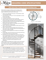
Mylen STAIRS CS60G09GS11 Installation guide

Type
Installation guide
Illustrations are general and may not match your specific stair design.
INSTALLATION MANUAL
42” and 60” HAYDEN
MP-4 R0
2 www.mylenstairs.com
3 www.mylenstairs.com
IMPORTANT MESSAGE
On behalf of everyone at Mylen Stairs, we would like to thank you for your purchase of one of our products. This
product is designed and manufactured in the USA. This stair comes with an Installation Manual. It is important that
you read and fully understand this manual prior to installation. Following the steps exactly as specified in the
manual will ease installation and reduce the amount of time necessary to complete the process. Keep this
manual even after the installation process has been completed. Understand how to use tools that may be
required during the installation process. Observe all safety warnings called out in this manual. Make sure those
who may install this product for you understand this manual as well as you do.
Mylen Stairs
106 GP Clement Drive
Collegeville, PA 19426
Table of Contents
Preparing for Installation . . . . . . . . . . . . . . . . . .
4
Line Rail Baluster Installation. . . . . . . . . . . . . .
18-20
Parts & Hardware . . . . . . . . . . . . . . . . . . . . . . . .
5-6
Aluminum Handrail Forming . . . . . . . . . . . . . .
21-22
Wood Handling and Finishing . . . . . . . . . . . . . .
7
Checking the Handrail Curvature . . . . . . . . .
23
Base Positioning . . . . . . . . . . . . . . . . . . . . . . . . . .
8
Pulling the Handrail into a Spiral . . . . . . . . . .
24
Column Sleeve and Tread Installation. . . . . . . .
9-11
Aluminum Handrail Installation . . . . . . . . . . . .
25
Coupler and Column Segment Installation . . .
12-13
Platform Rail Installation . . . . . . . . . . . . . . . . .
26-27
Platform Installation . . . . . . . . . . . . . . . . . . . . . . .
14-17
Infill Installation . . . . . . . . . . . . . . . . . . . . . . . . .
28-29
NOTICE !!!
Unauthorized modifications may present extreme safety hazards and could also result in injury or product
damage. Mylen Stairs strongly warns against, rejects and disclaims any modifications, add-on accessories or
product alterations that are not designed, developed, tested and approved by Mylen Stairs Engineering
Department. Any Mylen Stairs product that is altered, modified or changed in any manner not specifically
authorized after original manufacture including the addition of “aftermarket” accessories or component parts
not specifically approved by Mylen Stairs will result in the Mylen Stairs warranty being voided. Any and all liability
for personal injury and/or property damage caused by any unauthorized modifications, add-on accessories or
products not approved by Mylen Stairs will be considered the responsibility of the individual(s) or company
designing and/or making such changes. Mylen Stairs will vigorously pursue full indemnification and costs from any
party responsible for such unauthorized post-manufacture modifications and/or accessories should personal
injury and/or property damage result.
This symbol means:
ATTENTION! BECOME ALERT!
Your safety and the safety of others is involved.
Signal word definitions:
The signal words below are used to identify levels of
hazard seriousness. For your safety and the safety of
others, read and follow the information given with these
signal words and/or the symbol shown above.
WARNING indicates a potentially hazardous situation which,
if not avoided, COULD result in death or serious injury.
CAUTION indicates a potentially hazardous situation which, if
not avoided, MAY result in minor or moderate injury. It may
also be used to alert against unsafe practices or property
damage.
DANGER indicates an imminently hazardous situation
which, if not avoided, WILL result in death or serious injury.
CAUTION used without the safety alert symbol indicates a
potentially hazardous situation which, if not avoided, MAY
result in property damage
4 www.mylenstairs.com
Preparing For Installation
Read the Installation Manual
If anyone involved in the installation process cannot read English, it is the owner's responsibility
to explain the contents of this manual to them.
If any portion of this manual is unclear, contact the Mylen Stairs Customer Service Department
for clarification.
It is the owner’s responsibility to be familiar with the use of any tools that may be necessary to
complete the installation of this product. Read the manual for these specific tools.
Do not install or allow anyone to install this product if there are any questions about the
installation process.
Never attempt to install this product if any of the components are damaged or have any
unauthorized modifications.
All persons should be trained. The owner is responsible for training the users.
Wear the appropriate personal protective equipment during installation.
Wear hearing protection.
Wear safety glasses.
Wear a dust mask to avoid breathing dust.
Never allow children, unskilled or improperly trained people to participate in the installation
process.
Keep the Installation Manual legible and intact.
Do not attempt to install this product while under the influence of drugs or alcohol.
The owner/user can prevent and is responsible for accidents or injuries occurring to
themselves, other people or property.
Site Preparation
Check the area where the product is to be installed.
Be sure the area is clear of pets and people, especially young children. Stop the installation
process if any enter the area.
Installation should be done in daylight or in good artificial light.
Only use components approved by the manufacturer.
Installation Preparation
Do not tamper with any component.
Use extra care when unloading or moving any component. Some components may be heavy
and require multiple people to move them safely.
Keep all fasteners such as nuts and bolts well secured.
Verify that all components are in good condition and are not damaged in any way.
Do not start the assembly process until you read the Installation Manual.
Do not use the stair until the assembly process is complete.
Suspending the Installation Procession
If it is necessary to suspend the installation process, it is the owner’s responsibility to mark off the
area to limit access until the installation is complete.
Do not allow anyone to use the stair until the assembly process is complete.
5 www.mylenstairs.com
Parts & Hardware
Base
Baseplate Cover
Sleeve
Centering Ring
Tread
Threaded Coupler
Treaded Coupler w/ nut
Column Segment
(both ends threaded)
Platform
Column Cap
Platform Nut Spacer
Platform Bracket
Baluster Cup
Handrail
Platform Rail Post
(with set screw holes)
Platform Rail Post
21
Platform Rail Capping
22
Baluster Line Rail Mount
23
Line Rail Cup
24
SS Line Rail - Coiled
26
SS Line Rail - Straight
27
Threaded Rod
28
Platform Rail Mount Plate
6 www.mylenstairs.com
Item
Description
Item
Description
3/8”x3” Lag Screw
#10-32x1-1/2” Flat Head
Type F Screw
3/8” Flat Washer
#7x1-1/2” Fillister Head
Screw
5/8”-11 Hex Nut
5/16”-18x5/16” Set Screw
5/8” Structural Washer
5/16”-18x1-1/2” Hex Drive
Flat Head Screw
5/16”-18 x 1” Hex Drive Flat
Head Screw
5/16”-18x2-1/2” Hex Drive
Button Head Screw
5/16”x.875” OD Flat Washer
5/16”x1-1/4”OD Flat
Washer
5/16”-18 Hex Nut
#12-14x1-1/2” SQ Drive Self
Drilling Screw
5/16”-9 Grade A Zinc Finish
Hex Head Lag Screw
#12-14x1” Flat Head Self
Drilling Screw
¼”-20 x 3/8”
Socket Set Screw
#12-24x3/4” Phillips Head
Type F Screw
#10-16x1” Self Drilling Truss
Head Screw
#12-11x1 Flat Head Screw
#12-11x1” Pan Head Screw
#12-14x1” Pan Head Self
Drilling Screw
#10-16x3/4” Pan Head Self
Drilling Screw
#12-14x3/4Flat Head SQ
Drive Self Drilling Screw
7 www.mylenstairs.com
WOOD HANDLING AND FINISHING
READ BEFORE STARTING INSTALLATION
WOOD HANDLING
UNFINISHED TREADS AND HANDRAILS ON THE JOB SITE WILL ABSORB MOISTURE FROM THE
AIR. THESE MUST BE SEALED WITHIN 1 WEEK TO AVOID ADVERSE AFFECTS ON THE WOOD.
NEARBY PLASTERING, TILE WORK, CEMENT OR BRICKWORK INTRODUCE ENOUGH WATER IN
THE IMMEDIATE ENVIRONMENT FOR THE WOOD TO BE AFFECTED.
IF NEEDED, STORE THE WOOD PROVIDED IN A COOL, DRY AND STRUCTURALLY STABLE
LOCATION.
WOOD FINISHING
A. SAND ALL WOOD SURFACES BEFORE APPLYING ANY STAIN OR POLYURETHANE. NEARLY
ALL PROBLEMS WITH FINISHING OCCUR DUE TO IMPROPER SANDING PRIOR TO STAIN OR
POLYURETHANE APPLICATION. TREADS MAY RUB TOGETHER, OR AGAINST OTHER
SURFACES DURING HANDLING AND TRANSPORTATION. THIS MAY CREATE "SHINY SPOTS"
WHICH PREVENT AN EVEN FINISH. TAKE PRECAUTIONS WHEN TRANSPORTING TREADS.
B. SAND ALL WOOD SURFACES WITH 100 TO 220 GRIT RATING.
C. APPLY A STAIN IF ANY COLOR OTHER THAN THE NATURAL FINISH IS DESIRED.
D. THREE COATS OF SEALER MUST BE APPLIED TO ALL WOOD SURFACES. INADEQUATE
FINISHING OF ALL SIX SIDES OF A TREAD (WHICH INCLUDES THE BOTTOM) WILL ALLOW
MOISTURE TO BE ABSORBED.
E. CHECK WITH YOUR PAINT SPECIALTY DEALER FOR FURTHER INSTRUCTIONS IF NEEDED.
8 www.mylenstairs.com
Base Positioning and Installation
1. Measure the platform from the mounting face to the center of the large
hole to determine where to mount the base (1).
NOTE: Alternatively, you can lay the platform on the lower floor to get a
layout for where the column will fall. This is only possible if the mounting
wall(s)/surface(s) extend all the way to the lower floor and are plumb.
2. After positioning the base, fasten it to the floor with hardware (A) and
hardware (B).
3. Slide the baseplate cover (2) over the base (1).
The lag screws securing the base to the floor must be installed
and fully tightened before continuing with the installation
process. Failure to do so could cause the stair to be unstable
and could result in serious injury or death.
Hardware
Parts
Tools
9 www.mylenstairs.com
Adjustable Column Sleeve and Tread Installation
1. Slide a sleeve (3) onto the base column and guide it through the
baseplate cover.
2. Slide a Clear centering ring (4) onto the base column with the flanges
facing down
3. Most stairs will need spacers (5). The number of spacers can be found by
first sliding the tread (6) over the column. Press the tread firmly down onto
the sleeve and measure the height.
4. The spacers are 1/8” (.125”) thick. Calculate how many spacers will be
needed under the tread to raise the tread from the measured height with
no spacers to your riser height. You can calculate your riser height by
using the following simple calculation.
a. Add number of treads and platforms = _______
b. Measure the floor to floor height in inches = ______
c. Divide 4b by 4a = ______ (This is the riser height of your stair)
d. Riser height is usually between 8 ½” and 9 ½”.
NOTE: Treads may need anywhere from 0 to 8 spacers underneath the tread
to raise the tread up to the riser height calculated in Step 4.
Hardware
Parts
③④⑤⑥
Tools
10 www.mylenstairs.com
5. If spacers are required, remove the tread and add the correct number of
spacers on top of the sleeve. All spacer must go on top of the first sleeve.
NOTE: The spacers have small bosses on one side and indents on the other.
The bosses should sit in the indents of the adjacent centering ring or spacer.
6. Reinstall the tread (6) on top of the spacers (if any were required) and
remeasure the height of the top of the tread. It should be within 1/8” of
the riser height calculated in Step 4.
7. Slide a centering ring (4), sleeve (3), and centering (4) down the column.
Ensure that the flanges of the centering rings extend into the sleeve.
11 www.mylenstairs.com
8. Slide a tread (6) down the column. Press the tread firmly down onto the
sleeve and measure the height from the top of the tread to the floor.
9. Because this is the second tread, the height from the floor to the top of the
tread should be two times the riser height calculated in Step 4. Calculate
how many spacers will be needed under the tread to raise the tread from
the measured height (without spacers) to two times the riser height of the
stair.
10. If spacers are required, remove the tread and add the correct number of
spacers on top of the sleeve. Reinstall the centering rings (4), sleeve (3),
tread (6) and spacers (5) if needed.
NOTE: If several spacers are required, they can be placed above and below the
sleeve for a more even appearance as shown above. (not applicable to the
sleeve below the first tread)
11. Verify that the height from the top of the tread to the ground is within 1/8”
of two times the stair riser height calculated in Step 4. Add or remove
spacers if off by more than 1/8”.
12. Repeat until the next sleeve will no longer fit on the column. Orient the
treads so that they alternate being on the left and right to help balance
the stair. They will be spun into position in later steps.
Do not stand on the treads until after the platform and
balusters are fully installed in later steps. Ensure that the stair is
adequately braced while installing treads and additional
column segments in the next steps. Failure to brace the stair
could result in serious injury or death.
12 www.mylenstairs.com
Column Coupler and Column Segment Installation
NOTE: The column comes in segments that are connected with threaded
couplers. The column segments with threads in both ends are installed first. The
column segment with threads in only one end (10) will be cut to length and
installed at the top with the threaded coupler with the nut (8). See below for
where to cut the segment.
Use these items first
Use these items last (at the top of the stair)
1. Screw a threaded coupler (7/8) all the way into the column segment
below.
2. Screw the next column segment (8/9) onto the threaded coupler installed
in the previous step.
NOTE: Ensure that you use all threaded couplers and column segments with
threads in both ends (7&9) BEFORE using the segment and coupler meant to be
used at the top (8&10). Shorter stairs may only need the top segment and
coupler (7&9). The threaded coupler with the nut (8) must be installed with the
nut facing down.
3. Repeat steps 8-11 from the previous section, adding column segments as
needed. Stop when you get to installing the top segment (10) because it
must be cut to length.
Hardware
Parts
⑦⑧⑨⑩
Tools
13 www.mylenstairs.com
4. Screw the top column segment in and mark where the top of the platform
will be in the column. Typically the top surface of the platform will be flush
with the top floor.
5. Measure 4 down from the mark. Remove the top segment and cut at this
line.
6. Reinstall the top column segment after cutting it to size. Add the
remaining treads.
14 www.mylenstairs.com
Platform Installation
1. Screw the threaded rod (27) into the nut in the column. The threaded rod
should protrude approximately 6” up past the top of the column segment.
2. Slide the spacers (5) (if needed) centering rings (4) and sleeve onto the
column segment. Use the same number of spacers as the tread below.
Do not install the platform unless the stair is braced. The
weight of the platform could cause the stair to become
unstable. Failure to brace the stair could result in serious injury
or death.
3. Slide the platform (11) over the column. Temporarily hold the platform in
position on the surface it will be mounted to.
4. Check that the platform is level while holding it in position. If it is not level,
add or remove spacers below the platform to bring it to level.
Hardware
ⒶⒷⒸⒹ
ⒺⒻⒼⒽ
Parts
③④⑤⑪
⑫⑬⑭ 27
Tools
15 www.mylenstairs.com
5. The platform is reversible and will work with left hand up and right hand up
stairs. Identify and mark which side of the platform will be facing up and
which side will be facing down.
6. After marking the platform, remove it from the stair and fasten the
mounting brackets (14) to the bottom surface in locations shown below.
The brackets should be mounted flush to the edge of the platform. For a
wood laminate platform drill small 3/16” pilot holes in the locations for the
lag bolts (H). DO NOT DRILL THE PILOT HOLES COMPLETELY THROUGH THE
PLATFORM. Loosely secure the platform mount brackets to the bottom of
the platform with hardware (F) and (H).
16 www.mylenstairs.com
7. For metal platforms, loosely secure the platform mount brackets to the
bottom of the platform with hardware (E),(F) and (G). There are pre-drilled
holes where the mount brackets should be positioned.
8. With the mounting brackets installed on the bottom of the platform,
reposition the platform onto the column. Hold the platform in position and
fasten the mounting brackets to the wall using hardware (A) and (B). If
needed, 3/16” pilot holes can be drilled for hardware A.
9. Push the platform against the mount surface to eliminate any gaps, then
tighten all platform mounting hardware.
17 www.mylenstairs.com
10. Slide the column cap (12) onto the column and through the hole in the
platform. Ensure that the column cap is fully inserted and resting flush on
the platform.
11. Secure the platform to the column with the platform nut spacer (13) and
hardware (C) and (D). There should be between ½” and ¾” of threaded
rod above the nut. Spin the threaded rod until it is within this range, then
tighten the nut to 25 ft-lbs. This will compress the column and remove any
gaps between the treads and column segments. The column nut will be
fully tightened in later steps.
Do not stand on the treads or platform. They are not fully
secured at this time. Walking on the stair at this time could
cause the stair to become unstable and fall and result in
serious injury or death.
18 www.mylenstairs.com
Line Rail Baluster Installation
1. Slide a baluster (15) through the platform and tread below. Fasten
baluster line rail mounts (22) to the baluster with hardware (X). The line rail
mounts will prevent the baluster from falling through the hole in the tread.
Plumb the baluster by rotating the tread below before moving to the next
baluster.
NOTE: Make sure the baluster line rail mounts on the correct side of the baluster
for your specific installation. The angled profile on top of the baluster should
angle upward toward the top of the stair. There are small marks on each side of
the baluster to position the line rail mounts. Secure the baluster while installing
the hardware(X).
2. Repeat Step 1 until you reach the final baluster that goes from the bottom
tread to the floor. This baluster must be cut to size.
a. Metal treads - cut 5/8” off the bottom of this final baluster.
b. Laminate treads cut 1-7/8” off the bottom of this final baluster.
3. Slide the final baluster through the bottom tread. Use the level to plumb
the baluster while it is resting on the floor. Mark the floor in the location of
the final baluster and remove the final baluster.
4. Lift the second to last baluster to allow the final tread to swing out of the
way. Position the baluster cup (16) on the location marked in Step 3 and
fasten it to the floor with hardware (K).
5. Swing the last tread back into position and slide the final baluster through
the tread and into the baluster cup. Fasten the line rail mounts (22) to this
baluster with hardware (U). At this point all the balusters should be in
location but able to rotate freely.
Hardware
ⒾⒿⓀⓍ
Parts
⑮⑯ 22 23
24
Tools
19 www.mylenstairs.com
6. Start at the bottom baluster of the stair and slide the line rail cups (23) onto
the lowest line rail mount and partially tighten the set screws closest to the
baluster. The set screws should be tight enough to allow the line rail cups
to still rotate.
7. Take a coiled section of stainless steel line rail (24) and insert it through the
line rail cup installed in Step 6. Tighten the set screws to lock the line rail in
place.
8. Slide a line rail cup down the line rail and secure it to the next baluster.
Repeat this for the rest of the balusters. Tighten all the set screws after the
line rail is installed.
NOTE: Only install the first line rail. The balusters now need to be fastened to
the floor, treads, and platform.
20 www.mylenstairs.com
9. Fasten the bottom baluster to the baluster cup using hardware (L).
10. Fasten the balusters to the treads and the platform using hardware (I) for
metal treads or hardware (J) for laminate treads. Be sure to push the
balusters up until they are flush with the bottom of the tread before
installing the hardware.
NOTE: Do not install the other line rails at this time. Wait until after the handrail
is installed in the next steps before installing the remaining line rails. The top
two line rails can interfere with the installation of the handrail.
  • Page 1 1
  • Page 2 2
  • Page 3 3
  • Page 4 4
  • Page 5 5
  • Page 6 6
  • Page 7 7
  • Page 8 8
  • Page 9 9
  • Page 10 10
  • Page 11 11
  • Page 12 12
  • Page 13 13
  • Page 14 14
  • Page 15 15
  • Page 16 16
  • Page 17 17
  • Page 18 18
  • Page 19 19
  • Page 20 20
  • Page 21 21
  • Page 22 22
  • Page 23 23
  • Page 24 24
  • Page 25 25
  • Page 26 26
  • Page 27 27
  • Page 28 28
  • Page 29 29

Mylen STAIRS CS60G09GS11 Installation guide

Type
Installation guide

Ask a question and I''ll find the answer in the document

Finding information in a document is now easier with AI