Manufactured in the USA
3-YEAR WARRANTY. Please register at www.ezaccess.com/warranty-satisfaction.
© EZ-ACCESS®, a division of Homecare Products, Inc. All rights reserved.
All text and images contained in this document are proprietary and may not be shared, modified, distributed,
reproduced, or reused without the express written permission of EZ-ACCESS.
19708 05-08-2020
PATHWAY® HD Code Compliant Modular Access System
Installation Supplement for
PATHWAY® HD Step Adjustable Leg Kit
Use this Supplement alongside the PATHWAY® HD Code Compliant Modular Access System Installation
Manual and the Installation Supplement for PATHWAY® HD Steps

IN
Installation Supplement for PATHWAY® HD Step Adjustable Leg Kit
Page 2 of 5
INTRODUCTION
This Supplement addresses installation of the PATHWAY® HD Step Adjustable Leg Kit. Refer to the Installation
Supplement for PATHWAY® HD Steps for instructions relevant to the step and its related components.
Additionally, refer to the PATHWAY® HD Code Compliant Modular Access System Installation Manual for
instructions relevant to ramps, platforms, and related components. If you do not understand which manuals
apply, or their content, do not use the system and call 1-800-451-1903 for further information.
SYMBOL MEANINGS
The WARNING symbol indicates a potentially hazardous condition/situation. The safety warnings
throughout this manual, and on your equipment, if any, are for the protection of people and property.
Failure by any operator to abide by safety warnings will result in a waiver of all liabilities, loss of your
warranty, and could result in equipment damage and or failure, property damage, risk of serious bodily
injury, and or death. The symbol may appear in various colors and in conjunction with other symbols
and with or without the written word “WARNING”.
The NOTE symbol indicates important information. Failure to obey all notes could result in improper
operation, less-than-optimum equipment performance, and at the sole discretion of the equipment
manufacturer, may void your warranty. The symbol may appear in various colors and in conjunction
with other symbols and with or without the written word “NOTE”.
WARNINGS
STEP Uniform Live Load Rating: 100 pounds per square foot (psf) and a concentrated vertical load of
300 pounds over an area of 4 square inches. Do not exceed Uniform Live Load Rating.
PLATFORM Rated Load: 100 lb. psf live load, 300 lb. concentrated. Do not exceed Rated Load.
Prior to installation and use, read, understand, and follow the information in this manual and all other
applicable manuals, including supplements and addendums, if any, and warning labels, in their entirety.
Learn and understand the location and function of all features, warnings, Rated Loads, safety devices,
and labels before use. If you do not understand which manuals apply, or their content, do not use the
PATHWAY HD Code Compliant Modular Access System and call 1-800-451-1903 for further information.
Always follow all warnings and safety directives.
Maintaining all labels and manuals in legible condition is required by the system owner and is
essential for safe operation. Do not remove product safety labels. If any labels are missing,
damaged, or become illegible, they must be replaced. An illegible label will fail to alert individuals on
or around the system of a procedure or hazardous operating conditions. To obtain replacement
copies of instructions, warnings, and labels, call 1-800-451-1903.
For additional care, usage, or general safety information, please call 1-800-451-1903.

IN
Installation Supplement for PATHWAY® HD Step Adjustable Leg Kit
Page 3 of 5
ATTENTION INSTALLER and END USER
Prior to installation and use, read, understand, and follow the information in this manual and all other
applicable manuals, including supplements and addendums, if any, and warning labels, in their entirety.
Learn and understand the location and function of all features, warnings, Rated Loads, safety devices,
and labels before use. If you do not understand which manuals apply, or their content, do not use the
PATHWAY HD Code Compliant Modular Access System and call 1-800-451-1903 for further information.
Leave this Installation Manual with the end user.
Fill out online warranty registration.
IMPORTANT SHIPPING INFORMATION
The shipment contains a packing list. Confirm all items are present before starting installation. Open
shipping boxes and inspect for damage or missing parts. If damaged or missing parts are noted, do
not install or use.
Check for shipping damage immediately upon receipt and note any freight damage on freight bill
while driver is still present. Contact shipper right away with any freight damage concerns. In most
cases, freight damage claims will not be allowed unless noted on the freight bill. Pictures of damage
before the unit is unpacked can be very helpful.
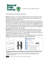
TOOLS TYPICALLY REQUIRED
POWER
DRILL
LEVEL
MARKER OR PENCIL
11/32″ OR 3/8” DRILL BIT
1/2″ SOCKET
3/16″ ALLEN WRENCH
RUBBER MALLET
TORQUE WRENCH (CAPABLE OF UP TO 317 IN.-LBS.)
TAPE MEASURE
C-CLAMPS (QTY 2)

IN
Installation Supplement for PATHWAY® HD Step Adjustable Leg Kit
Page 4 of 5
1. INSTALL ADJUSTABLE LOWER LEG BRACKETS AND LEGS
1.1. With the exception of the ‘LEVELING FEET’ section in the Installation Supplement for PATHWAY HD
Steps, assemble and set all platforms, platform guards or two-line rails, and steps as described in the
main PATHWAY HD Code Compliant Modular Access System Manual (if applicable) and the
Installation Supplement for PATHWAY HD Steps.
1.1.1. Instead of leveling feet, adjustable leg brackets (‘bracket’) and lower legs (‘leg’) will be
used as an alternate method to support the bottom of the riser.
1.2. Use a c-clamp or similar device to hold a bracket against the riser side rail at 1/2” from the 2” square
lower riser corner pocket and 1-1/4” below the top of the pocket (FIG. 1.1).
1.3. Repeat for other opposite side of riser.
1.3.1. Clamp both brackets in place. Before drilling holes (completed in an upcoming step),
ensure that no installation issues are noted.
1.4. Use a level on each bracket, ensuring that it is situated to allow leg to be perpendicular to the
ground plane when inserted into the bracket.
1.5. Use holes in the bracket as a template to drill 3/8” or 11/32” holes straight through both walls of the
riser side rail. Or, alternately, mark the location, remove bracket, drill holes, and then re-clamp the
bracket in place.
1.5.1. On each side of the riser, you should end up with two holes above the first riser tread and
two holes below the first riser tread (FIG. 1.2).
1.6. Insert a leg into the bracket. Orient the bracket so that the leg set screws are on the side facing the
lower riser corner pocket and orient the leg so that it extends under the riser and away from the
lower end of the riser as shown (FIG. 1.2)
1.6.1. Tighten set screws just enough to hold the leg in place while the bracket is being attached.
FIG. 1.1
FIG. 1.2
DETAIL

IN
Installation Supplement for PATHWAY® HD Step Adjustable Leg Kit
Page 5 of 5
1.7. Using a 3/16″ Allen wrench and a 1/2″ socket or 1/2″ wrench, attach the bracket (with leg installed)
to the riser side rail using 5/16”-18 x 2-1/2” button head socket cap screws, 5/16”-18 locknuts, and
5/16” flat washers oriented with cap screw and one washer on the riser side and the locknut and a
second washer on the bracket side (FIG. 1.3). Tighten fasteners securely.
1.8. Loosen the bracket set screws just enough to allow the leg to contact the ground and support the
riser. Retighten set screws to 317 in.-lbs.
Do not lean, walk, or otherwise bear weight on the step until installation is complete.
1.9. Repeat the process for the opposite side of the riser.
1.10. Install 1-1/2” square tube plugs into the top of each leg. Use a rubber mallet or similar tool to fully
seat the plug if needed (FIG. 1.4).
1.11. Complete all remaining steps in the main PATHWAY HD Code Compliant Modular Access System
Manual and the PATHWAY HD Step Supplement, as required for the system.
2. FINAL CHECKS AND INSPECTION BEFORE USE
2.1. Ensure all fasteners are in place and secure.
2.2. Ensure that the level and slope has not shifted during installation.
2.3. Remove any debris and metal chips.
2.4. Walk on the assembled system, checking for any undue movement. If undue movement is
discovered, review the assembly process to ensure no processes were missed. If that does not
resolve the undue movement, do not use the system and call at 1-800-451-1903 for further
direction.
FIG. 1.3
FIG. 1.4
/