Page is loading ...

Workrite Ergonomics | (800) 959–9675 www.workriteergo.com 1 of 12
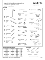
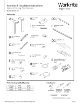
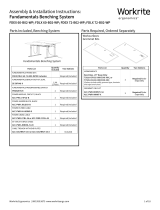
Parts Included
U Leg Cable, 1 Meter
Qty: 2
V #12 x 2" Flat Head Screw
Qty: 2
T Corner Glide
Qty: 1
B Rear Bracket
Qty:3 R Connector Bracket
Qty: 2
A Legs
Qty: 3
S Corner End Bracket
Qty: 1
C Short Bracket
Qty: 3
D Le End Bracket
Qty: 1
E Right End Bracket
Qty: 1
F 4 mm Allen Wrench
Qty: 1
G #M6 × 14 mm Flat Head Cap
Screw
Qty: 32
H Foot Glide
Qty: 4
J Control Box
Qty: 1
N Leg Cable, 2 Meter
Qty: 1
K Cable Spool
Qty: 3
M " P-Loops
Qty: 15
L #8 × ⅝" Pan Head Screw
Qty: 17
I #12 × ¾" Pan Head Screw
Qty: 53
O Power Cable
Qty: 1
P Feet
Qty: 2
W
Glide Adjuster Center Foot
Qty: 4
Worksurface Required, Sold Separately:
Equal Corners Width Left Width Right Depth
24" Feet 58–72" 58–72" 23–24"
30" Feet 58–72" 58–72" 29–30"
Left Offset Corners Width Left Width Right Depth
24" Feet 58–72" 46–60" 23–24"
30" Feet 58–72" 46–60" 29–30"
Right Offset Corners Width Left Width Right Depth
24" Feet 46–60" 58–72" 23–24"
30" Feet 46–60" 58–72" 29–30"
Cordless Drill #2 Phillips Bit
Screwdriver or
Driver/Drill
⅛" pilot drill bit
pencil
3⁄32" pilot drill bit
#3 Phillips Bit
Screwdriver or
Driver/Drill
Tools Required:
or
Q Standard, Bluetooth, or
Programmable Switch
Qty: 1
Assembly & Installation Instructions:
Fundamentals 3-Leg Work Center
FDEX/FDLX5472-4272EOC

2 of 12 Workrite Ergonomics | (800) 959–9675 www.workriteergo.com
SAVE THESE INSTRUCTIONS
WARNING: Maximum equipment loading of table assembly in addition to specied top is as follows:
Maximum Top Weight: 116 lb (52.7 kg)
Maximum Equipment Load: 200 lb (90.9 kg)
Loading should be evenly distributed over table surfaces.
V = 120 VAC, 60 Hz / 4 A maximum
FLAMMABILITY: All worksurfaces used must meet UL 962 ammability requirements
Flame Spread Rating maximum 200
Smoke Developed Index maximum 450
WORKSURFACE MATERIAL: This frameset is designed to accommodate worksurfaces made from Industrial Particle Board with nominal thickness
of 1.125". If the worksurface is not appropriate or not mounted correctly to the table, it could cause the complete table to be unstable, it may collapse,
and for an adjustable table, the electrical components may fail.
Intended for indoor use only.
For commercial use only.
IMPORTANT SAFETY INSTRUCTIONS:
When using an electrical furnishing, basic precautions should always be followed, including the following:
Read all instructions before using this Fundamentals Work Center.
DANGER: To reduce the risk of electric shock, always unplug this Fundamentals Work Center from the electrical outlet before cleaning or servicing.
WARNING: To reduce the risk of burns, re, electric shock, or injury to persons:
1. Unplug from outlet before putting on or taking off parts.
2. Close supervision is necessary when this furnishing is used by, or near children, invalids, or disabled persons.
3. Use this Fundamentals Work Center only for its intended use as described in these instructions, do not use attachments not
recommended by the manufacturer.
4. Never operate this Fundamentals Work Center if it has a damaged cord or plug, is not working properly, has been dropped
or damaged, or dropped into water. Return the furnishing to a service center for examination and repair.
5. Keep the cord away from heated surfaces.
6. Do not operate outdoors.
7. Do not operate where aerosol (spray) products are being used or where oxygen is being administered.
8. To disconnect, remove plug from outlet.
9. Do not exceed maximum load recommendations.
Polarized Plug Instructions (Only applicable to products having a polarized plug power cord):
Some products include a polarized plug—see Figure A (One A/C plug blade wider than the other)—to reduce the risk of
electrical shock. A polarized plug only ts a polarized power outlet one way. If the polarized plug does not t properly into the
electrical outlet turn the power plug over to see if it then ts properly and fully into the outlet. If the plug does still does not t
the outlet, contact a certied electrician to install the correct matching polarized electrical outlet.
Caution: Never modify the power cord plug in any way
Double-Insulated Products Instructions:
Some products are double-insulated. No means of grounding is required or provided on a double-insulated product; nor is a
means for grounding to be added to the product. The plug in a double insulated system is shown in Figure A. Double-insulated
products are indicated with markings of “double-insulated” or the “double box symbol” or both.
Grounding Instructions (For grounded electric products only):
Products with grounded power cords are for use on a nominal 120 V circuit and has a grounded plug as shown in Figure B
Make sure the product is connected to an electrical outlet having the same conguration as the plug shown in Figure C.
Caution: Never modify, remove, or use adaptors that eliminate the ground connections from the grounded power cord
A/C Power:
Products sold in North America and other regions are 120 V A/C as marked on the power supply/control box of the furnishing
and are to be used on a normal 120 V A/C circuit. Always follow the instructions above for power connection using grounded or
double insulated power cords as supplied.
• Only use power cord(s) supplied with your electric product
• Never modify, alter, use an adaptor, or change the electrical system of this product in any way.
Warning: Doing so may cause risk of electrical shock or re
Illustration Disclaimer—Power Plug and Receptacle Images:
In some cases, the images in this instruction may not match the power cord supplied with your electrical furnishing based on your region.
Plug type, blade size, and shape may change.
Grounding Pin
Figure B
Grounded Outlet
Figure C
Polarized Plug
Figure A

Workrite Ergonomics | (800) 959–9675 www.workriteergo.com 3 of 12
61"
55"
49"
43"
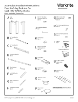
1 Assemble Rear Connected Stretcher Bracket Set
Assemble Rear Brackets (B) to Connector Brackets (R) with
four #M6 × 14 mm Flat Head Cap Screws (G).
Use this guide to determine the correct holes for mounting
based on the width of your Worksurface.
Tighten securely.
To avoid stripping the threads, always
insert and make the first few turns
of the screw BY HAND with an Allen
wrench (F), ensuring it is in straight.
70" W × 23" D or
76" W × 29" D Worksurfaces
64" W × 23" D or
70" W × 29" D Worksurfaces
58" W × 23" D or
64" W × 29" D Worksurfaces
52" W × 23" D or
58" W × 29" D Worksurfaces
G
G
G
R
R
R
R
F
Note!
Only use the #M6 × 14 mm Flat
Head Cap Screw (G) for assembly.
B
B
B
B
B
B
B
B
G
Note: Brackets can be sized in 3"
increments for any non-Workrite top.
Connected Side,
Right Configuration Connected Side,
Le Configuration
When shown upside down, right will be on your le and vice-versa. Your frameset may dier.
G#M6 × 14 mm Flat Head
Cap Screw
Hardware at actual size

4 of 12 Workrite Ergonomics | (800) 959–9675 www.workriteergo.com
37.75"
34.75"
21"
43.75"
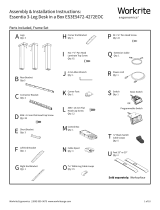
2 Assemble Rear Floating Bracket - Shorter or Equal Side
Assemble Rear Brackets (B) to Connector Bracket (R )
with two #M6 × 14 mm Flat Head Cap Screws (G).
Use this guide to determine the correct holes for
mounting based on the width of your Worksurface.
Tighten securely.
R
R
R
B
B
B
B
Floating Side,
Right Configuration
Floating Side,
Le Configuration
To avoid stripping the threads, always
insert and make the first few turns
of the screw BY HAND with an Allen
wrench (F), ensuring it is in straight.
When shown upside down, right will be on your le and vice-versa. Your frameset may dier.
Use with 70"× 23",
70"×29" or
64"×23" widths
Use with 64"× 29"
or 58"×23" widths
Use with 58"×29" widths
G
G
G
F
Note: Brackets can be sized
in 3" increments for any
non-Workrite top.
Use with 42"– 48" widths
Note!
Only use the #M6 × 14 mm Flat
Head Cap Screw (G) for assembly.
G#M6 × 14 mm Flat Head
Cap Screw
Hardware at actual size

Workrite Ergonomics | (800) 959–9675 www.workriteergo.com 5 of 12
3 Attach Short & Medium Brackets
3.1 Attach Short Brackets (C) using #M6×14 mm Flat Head Cap
Screws (G) to all three Legs.
3.2 Attach Right End Bracket (E) to sides of the Right Leg (A) using #M6 × 14 mm Flat Head Cap Screws (G). Attach
Le End Bracket (D) to sides of the Le Leg (A) using #M6 × 14 mm Flat Head Cap Screws (G). Attach Corner End
Bracket (S) to the Center Leg (A) using #M6 × 14 mm Flat Head Cap Screws (G).
3.3 Attach both the Connected Rear Bracket (B and B & R assembled) and Floating Rear Bracket (B or B & R
assembled) using #M6 × 14 mm Flat Head Cap Screws (G).
3.4 Make sure the Connected Rear Bracket is on the longer of the two sides.
Tighten securely.
Note: The Right End Bracket (E) will be on
your le when upside down.
Note: Le configurations will assemble as
a mirror image of these instructions.
Le Leg
Center Leg
Right Leg
Three piece
Connected Rear Bracket
B and B & R assembled Floating Rear Bracket
B or B & R
Le End Bracket
C
C
G
G
G
G
GG
G
B
F
G
G
C
S
A
A
D
E
A
Hardware at actual size
G#M6 × 14 mm Flat Head
Cap Screw
Caution!
Only use the #M6 × 14 mm Flat Head
Cap Screw (G) for assembly.
Right configuration
44" & 48" configurations have a single Floating
Rear Bracket B on the shorter side.
3.1
3.2
3.2
3.2
3.3
3.3
3.4
3.4
3.3
3.1
3.1
Le configuration
To avoid stripping the threads, always
insert and make the first few turns
of the screw BY HAND with an Allen
wrench (F), ensuring it is in straight.
Right End Bracket
44" & 48" configurations

6 of 12 Workrite Ergonomics | (800) 959–9675 www.workriteergo.com
2.875"
2.875"
C
L
C
L
>¾"
5 Attach Base to Worksurface
5.1 Position the base assembly onto the top. Place the right and le leg in 2" from end brackets to the outside
edges of the top. Next center the feet front to back over the depth of the top. Make sure the stretchers are
parallel to the rear edge before drilling.
5.2 Using the ⅛" drill bit, pilot drill the six end bracket locations as shown. Be careful to not drill through the worksurface!
5.3 Install six (6) #12 × ¾" Pan Head Screws (I) using a #3 Phillips Screw bit in the corner locations and tighten
securely. Do Not Overtighten!
Install Feet and Glides to Leg Assemblies
4.1 Install Corner Glide (T) to bottom of center leg (A).
4.2 Install outside feet using eight #M6 × 14 mm Flat
Head Screws(G) included with this Frame Set.
4.3 Install the remaining Foot Glides (H) to bottom of
the Feet (P) supplied in your Foot Kit.
Note: Avoid trip or tip hazards!
For uniquely shaped, non-standard worksurfaces, it is the installers
responsibility to position the worksurface to minimize extended
overhangs and position feet fully under the worksurface.
5.1
5.1
5.2 5.3
5.3
5.3
I
I
T
A
P
G #M6 × 14 mm Flat
Head Cap Screw
Hardware at actual size
Note!
Only use the #M6 × 14 mm Flat Head
Cap Screw (G) supplied with Corner
Foot and Foot Kit for assembly.
H
G
H
4.3
4.1
4.2
4

Workrite Ergonomics | (800) 959–9675 www.workriteergo.com 7 of 12
>¾"
Finish Installing Screws to Attach Base to Top
6.1 Using the " Drill Bit, pilot drill the remaining mounting holes in all bracket locations as shown
Be careful to not drill through the worksurface!
6.2 Install the remaining #12 × ¾" Pan Head Screws to all the remaining bracket mounting locations and
tighten securely.
Do Not Overtighten!
I
6.2
6.1
I #12 × ¾" Pan Head
Screw
Hardware at actual size
6

8 of 12 Workrite Ergonomics | (800) 959–9675 www.workriteergo.com
L #8 × ⅝" Pan Head
Screw
8"
8"
Attach Switch
7.1 Using dimensions shown, place the Switch (Q) on the desktop.
7.2 Using drill and a " drill bit, drill the two switch mounting holes as shown.
7.3 Attach the Switch (Q) as shown with two #8 × " Pan Head Screws (L).
Note: the Switch (Q) can be located on the Right or Le side of
the table as required.
8 Loop Power Cable & Center Leg Cable through Strain Relief on Control Box
8.1 Loop the Power Cable (O) through the
strain relief channel on the bottom of
the Control Box (J) as shown. Leave 8” of
slack to route cord.
8.2 Thread the 1 meter Leg Cable (U) from
the Center Leg through the cable channel
on the bottom of the Control Box as
shown. Leave 8" of slack to route cable.
8.3 Plug Power Cable (O) into power
outlet AC on the Control Box (J).
8.4 Plug Leg Cable (U) into port “3” on
the Control Box.
8.5 Lay the Control Box down in installation
location with cables in place.
0.75”
17.90mm
2.00”
50.80mm
Switch Housing
7
Hardware at actual size
8.3
8.4
O
O
U
J
J
U
U
8.2
8.1
bottom
Standard or Bluetooth Switch
Note: use the screws provided with Standard & BT-Proswitch
to mount the switch using the diagram above.
7.1
7.3
1/ 1/
L
Q
Programmable Switch

Workrite Ergonomics | (800) 959–9675 www.workriteergo.com 9 of 12
Attach Control Box & Cable Spools to Worksurface
9.1 Place Control Box (J) in position and use a pencil to mark pilot hole placement. Control Box should be placed
towards rear center of worksurface as shown. Remove Control Box and drill pilot holes where marked. Do not
drill all the way through tabletop!
9.2 With Control Box (J) positioned over pilot holes, attach with two #12 × ¾" Flat Head Screws (V).
9.3 Attach Cable Spool (K) with the #12 × ¾" Pan Head Screw (I) to underside of worksurface. Mount Cable Spools (K) in
a convenient location between legs and control box. Lay out Leg Cables (A) to be sure they all reach the Control
Box.
9.4 Lay out Leg Cables (N & U) to be sure they all reach the Control Box.
9.1
9.2
9.3
9.3
9.3
9.4
9.4
9.4
KK
N
U
K
I
I
I
VV
I #12 × ¾" Pan Head
Screw
Hardware at actual size
JU
V #12 × 2" Flat Head Screw
Hardware at actual size
9

10 of 12 Workrite Ergonomics | (800) 959–9675 www.workriteergo.com
10
Attach Cable Loops and Route Cables
10.1 Route cables as shown, using Cable Spools (K) to take up any slack. Use the 2 Meter Leg Cable (N) for the Leg
furthest from Control Box (J).
10.2 Attach P-Loops (M) to underside of worksurface using #8 × ⅝" Pan Head Screw (L) making sure to wrap the
P-Loop (M) around the cable prior to attaching. If you do not have a Workrite worksurface, attach P-Loops in
convenient locations between legs or switch and the control box.
Note the additional P-Loop and Cable Spool locations that may provide better attachment and routing options
for your specific configuration.
U
U
U
N
N
M
K
K
10.1
10.1
10.2
9.1
L
M
J
L #8 × ⅝" Pan Head
Screw
Hardware at actual size
Switch Cable
M
L
K
N
10.2

Workrite Ergonomics | (800) 959–9675 www.workriteergo.com 11 of 12
11
Connect Leg Cables, Control Cable and Power Cord to Control Box
11.1 Connect the Right Leg Cable (U) to the port on the Right Leg (A) and port “1”on the Control Box (J).
11.2 Connect the Center Leg Cable (U) to the port on the Center Leg (A).
11.3 Insert the Switch Cable into port “A1” on the Control Box (J).
11.4 Connect 2 Meter Leg Cable (N) to the port on the Le Leg (A) then to port “2” on the Control Box (J)
U
T
N
J
J
U
U
Switch Cable into
Switch Port “A1”
11.4
11.2
Installed in
Step 7
11.3
11.4
11.4
11.1
11.2
11.1

12 of 12 Workrite Ergonomics | (800) 959–9675 www.workriteergo.com
#1500458 Rev G
12
Put Work Center Upright and Connect Power Cord to the Power Supply
12.1 Turn the work center over into an upright position.
Note: Always use at least two people to flip and move work centers. Caution! Heavy!
12.2 Plug the Power Cable (O) into the power outlet.
15
Set Control Switch Initial Setting (FDLX models only)
15.1 Press the DOWN button to move table to its lowest position.
15.2 If using a worksurface other than a Workrite top, measure height of table from floor to top of worksurface.
If using a Workrite worksurface, the number to use will be 27.5".
15.3 Press and hold both the UP and DOWN buttons simultaneously. Three dashes will appear. Wait for the numeric
display to return.
15.4 Press the UP button until the display reads 27.5" (for Workrite worksurfaces) or measured height (for others).
15.5 The display will flash when the change has been saved.
13
Adjust Feet Glides
If necessary, adjust Foot Glides (M) on the feet to level the worksurface. Unscrew to increase height, screw in to
decrease height. For Center Foot, use "Glide Adjuster" as needed (comes in ¼" to ½" spacers).
✓ Cleaning instructions
To clean the legs, apply cleaner to a so cloth.
Suggested cleaners: Windex or Formula 409.
Do not use solvents and do not saturate or spray cleaners directly to work center base.
You must complete this
initialization step or your
work center will NOT
function properly.
Hold down the down
arrow until work center
moves slightly upwards!
✓ Replacement Parts
Visit http://workriteergo.com/documentation/other/workrite_ergonomics_pricing_specification_guide.pdf for
replacement parts.
14
Initialize Legs
Aer all legs and the switch are connected, and the power cord has been plugged in, hold the down arrow on
the switch until the legs make a short motion down and then back up. This initializes and synchronizes the work
center legs.
O
12.1
12.2
/