GLPP-DIMFLVEX-PM/GLPP-1DIMFLV2EX-PM/GLPP-1DIMFLV3EX
Crestron Green Light
®
Power Pack, Dimmer with inNET EX
®
Control
Installation Guide
Description
The Crestron Green Light Power Pack is a standalone room controller designed to
communicate with photocells, occupancy sensors, and control stations to automatically
control lighting in any room. The entire Crestron Green Light Power Pack (GLPP) family
provides cost-effective and powerful lighting control for classrooms, small ofces, and
open-plan ofces. Ideal for new construction as well as retrotting existing buildings,
Crestron
®
GLPPs are designed to install and commission quickly and easily. Additionally,
the GLPP can be connected to a central control system, enabling it to become an
integral part of the building energy management system.
Models
Additional Resources
Visit the product page on the Crestron website (www.crestron.com)
for additional information and the latest rmware updates. Use a QR
reader application on your mobile device to scan the QR image.
Available Accessories
The GLPP-DIMFLVEX-PM can be used with a variety of equipment.
Wiring
WARNING: Turn off the power to the GLPP-DIMFLVEX-PM before wiring. Wiring with
the power on can result in serious personal injury and damage to the device.
CAUTION: This product must be installed with 14 AWG (2.5 mm²) and 18 AWG (0.75
mm²) wires that comply with local electrical codes.
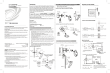
Typical Wiring Diagram
GLPP-DIMFLVEX-PM
Keyapd
Keypad
Photocell
GLS-ODT-C-NS
GLS-ODT-C-NS
(Additioanl,
Optional)
KEYPAD
White/Black
SW HOT SW HOT SW HOT
24V
PHOTO
OCC
IR
GROUND
Green/Yellow
GROUND
Green/Yellow
0–10 V
Fixture
0-10V
DIM (+)
0-10V
DIM (+)
0-10V
DIM (+)
0-10V
DIM (-)
COM
NEUT
White
NOTE: Connect the
brown IR wire to pin 5 on
the GLS-ODT-C-NS
NOTE
: Up to three
keypads can be used in a
GLPP system. Refer to the
“Available Accessories”
section for a list of
available keypads.
NOTE: Wire keypads in
parallel.
0–10 V
Fixture
0–10 V
Fixture
Commissioning
The GLPP-DIMFLVEX-PM must be commissioned before it can be used. During
commissioning, the scene selections are congured along with the daylighting levels.
The actions of the occupancy sensors are also congured.
Scene Settings
The following table shows the default scene settings.
Default Scene Settings
Change the Scene Settings
The scene settings can be changed to accommodate the needs of the room or
occupants. The scenes are changed through the GLPPA-REMOTE-PROG, the
GLPPA-REMOTE-USER, or the GLPPA-KP (all sold separately).
Edit the Scenes Using Remote
Use the GLPPA-REMOTE-PROG or the GLPPA-REMOTE-USER to change the default
scene settings for scenes 1 through 8.
1. Use LOAD 1 ON/OFF, LOAD 1 , or LOAD 1 buttons to set the load to the
desired level. Repeat this process for the other connected loads. Alternatively, use
the MASTER ON/OFF, MASTER , or MASTER buttons to set the levels of all
connected loads.
2. Press and hold the appropriate SCENE 1 through SCENE 8 button for 2 seconds to
save the scene. The GLPP beeps when the scene is saved.
NOTE: Only Scene 1 enables daylighting.
3. Repeat the steps above for all scenes that need to be congured.
Edit the Scenes Using 2-Wire Keypad
Use the GLPPA-KP as another means of editing the scenes if using the 4-button keypad
setup. Follow the procedure below to edit the scenes using the keypad.
1. Press and hold the ALL ON and ALL OFF buttons on the keypad for 3 seconds to
put the GLPP into Program mode. The LED on the keypad blinks to indicate that
the device is in Program mode.
• Program mode exits without saving after 30 seconds of button inactivity.
• Program mode immediately exits without saving when the ALL OFF button is
pressed.
2. In Program mode, the top three buttons can be used for manual control of loads 1
through 3. The ALL ON button controls load 1, the SCENE 1 button controls load 2,
and the SCENE 2 button controls load 3. The buttons operate in the following
manner:
• Press to toggle the load between full on and full off (no fade time). When the
button is pressed, the load turns full on if the load is currently off. The load stays
on if the load is currently on.
• Hold to cycle dim. Cycle dimming allows the device to dim to off as long as the
button is held through a 1-second pause at low end.
NOTE: All connected loads must be assigned a load level for each scene.
3. To save the current light levels to a scene, hold the ALL OFF button, and then tap
the SCENE 1 or SCENE 2 button that the levels should be saved to. The keypad
exits Program mode immediately upon saving, resetting a scene, or after 1 minute.
To reset a scene to its factory default levels, in Program mode, hold the ALL OFF button
and the desired scene button for 5 seconds.
SCENE DIMMING LEVEL
1 100% (All loads)
2 50%
3 25%
4 80%
5 60%
6 40%
7 20%
8 0%
3-5/16 in
(85 mm)
15/16 in
(24 mm)
3-3/8 in
(86 mm)
(8x) ø3/16
Mounting holes for
two 4x4 boxes.
9-13/16 in
(250 mm)
8-11/16 in
(221 mm)
2-1/2 in
(64 mm)
3-3/8 in
(86 mm)
3-3/16 in
(81 mm)
1-5/8 in
(42 mm)
4-1/4 in
(108 mm)
2-1/8 in
(54 mm)
Feed-through wires from
unit exit from this side.
NOTE: These models meet the requirements of UL
®
2043 for installation in an
environmental air-handling (plenum) space.
Physical Description
This section provides information on the connections, controls and indicators available on
the GLPP-DIMFLVEX-PM.
GLPP-DIMFLVEX-PM Overall Dimensions (Flying Leads Not Shown)
GLPP-DIMFLVEX-PM Series Specications
WARNING: To avoid re, shock, or death, turn off power at circuit breaker or fuse and
test that power is off before wiring!
NOTES: Observe the following points.
• Install and use this product in accordance with appropriate electrical codes and
regulations.
• A licensed electrician should install this product.
NOTE: Before using the GLPP-DIMFLVEX-PM, ensure the device is using the latest
rmware. Check for the latest rmware for the GLPP-DIMFLVEX-PM at
www.crestron.com/rmware. Firmware is loaded onto the device using Crestron
Toolbox™ software.
ACCESSORY DESCRIPTION
GLPPA-KP In-Wall Master Scene Keypad for GLPP
GLPPA-KP1 In-Wall Zone Keypad for GLPP, Channel 1 Control
GLPPA-KP2 In-Wall Zone Keypad for GLPP, Channel 2 Control
GLPPA-KP3 In-Wall Zone Keypad for GLPP, Channel 3 Control
GLPPA-KP4 In-Wall Zone Master Keypad for GLPP
GLS-OIR-C-NS Passive Infrared Ceiling Mount Occupancy Sensor
GLS-ODT-C-NS Dual-Technology Ceiling Mount Occupancy Sensor
GLS-LOL Crestron Green Light Photosensor, Open-Loop
GLS-LCL Crestron Green Light Photosensor, Closed-Loop
GLS-LEXT Crestron Green Light Photosensor, Outdoor
MODEL DESCRIPTION
GLPP-DIMFLVEX-PM Crestron Green Light Power Pack, 1-Channel 0–10V
Dimmer with inNET EX Control and Built-in Power
Monitoring
GLPP-1DIMFLV2EX-PM Crestron Green Light Power Pack, 2-Channel 0–10V
Dimmer with inNET EX Control and Built-in Power
Monitoring
GLPP-1DIMFLV3EX-PM Crestron Green Light Power Pack, 3-Channel 0–10V
Dimmer with inNET EX Control and Built-in Power
Monitoring
SPECIFICATION DETAILS
Load Ratings
Dim or Switched
Channels
1, 2, or 3 switched or dimmed (0–10 V) loads
(depending on model)
Per Unit 16 A at 100–277 Vac, 50/60 Hz (20 A, de-rated
to 80%)
Dim Load Types
(for dimming models)
0–10 V uorescent ballast (4-wire); 0–10 V LED
drivers; 60 mA max current sink
Power Requirements
Main Power 100–277 Vac, 50/60 Hz
Available Sensor Power 2.5 W at 24 Vdc (sufcient for powering multiple
sensors)
Enclosure 20-gauge galvanized steel enclosure; designed
for mounting to two (2) adjacent standard 4"
square electrical junction boxes (some models
may need a box extension to meet code
requirements);
3-channel versions require a box depth of 2.125
in (54 mm)

This product is Listed to applicable UL Standards and requirements by Underwriters Laboratories Inc.
Federal Communications Commission (FCC) Compliance Statement
This device complies with part 15 of the FCC Rules. Operation is subject to the following two
conditions: (1) This device may not cause harmful interference, and (2) this device must accept any
interference received, including interference that may cause undesired operation.
CAUTION: Changes or modications not expressly approved by the manufacturer responsible for
compliance could void the user’s authority to operate the equipment.
NOTE: This equipment has been tested and found to comply with the limits for a Class A digital
device, pursuant to part 15 of the FCC Rules. These limits are designed to provide reasonable
protection against harmful interference when the equipment is operated in a commercial environment.
This equipment generates, uses, and can radiate radio frequency energy and, if not installed and used
in accordance with the instruction manual, may cause harmful interference to radio communications.
Operation of this equipment in a residential area is likely to cause harmful interference in which case
Wireless Communications
The device connects to the Crestron network via the inNET EX communications
protocol. Use the procedures outlined below to join or leave an inNET EX network and
to verify communications between the device and the control system.
Joining an inNET EX Network
Before a device can be used in a lighting system, it must rst join an inNET EX network.
To join an inNET EX network, the device must be acquired by an inNET EX gateway.
NOTE: A device can be acquired by only one gateway.
1. Put the inNET EX gateway into Acquire mode from the unit itself or from Crestron
Toolbox™ software. Refer to the gateway’s manual at www.crestron.com/manuals
for details.
NOTE: In an environment where multiple gateways are installed, only one
gateway should be in Acquire mode at any time.
2. Put the device into Acquire mode:
a. Tap the top button three times and then press and hold it down
(tap-tap-tap-press+hold) until the top LEDs on the device blink once (this can
take up to 10 seconds).
b. Release the button to start the acquire process. The top LED blinks slowly to
show that the device is actively scanning the inNET EX network.
• The top two LEDs turn on for 5 seconds to show that the device has been
successfully acquired by the infiNET EX network.
• The top LED blinks fast to indicate that the device was not successfully
acquired by the infiNET EX network. Tap the top button to acknowledge the
failure. Ensure the gateway is in Acquire mode and within range before
attempting the acquire process again.
3. Once all devices have been acquired, take the gateway out of Acquire mode. Refer
to the gateway’s manual for details.
Leaving an inNET EX Network
To leave an inNET EX network, put the device into Acquire mode, as described in
“Joining an inNET EX Network” above, when no gateway is in Acquire mode.
Verifying Communications Status
To check the communications status of the device, tap the top button three times and
then press and hold it down (tap-tap-tap-press+hold) for up to 2 seconds. The LED
blinks to indicate the communications status. Refer to the following table for details.
Crestron Electronics, Inc. Installation - DOC. 7210C
15 Volvo Drive Rockleigh, NJ 07647 (2031030)
Tel: 888.CRESTRON 06.16
Fax: 201.767.7576 Specications subject to
www.crestron.com change without notice.
the user will be required to correct the interference at his own expense.
Industry Canada (IC) Compliance Statement
CAN ICES-3(A)/NMB-3(A)
The product warranty can be found at www.crestron.com/warranty.
The specic patents that cover Crestron products are listed at patents.crestron.com.
Certain Crestron products contain open source software. For specic information, please visit
www.crestron.com/opensource.
Crestron, the Crestron logo, Crestron Green Light, Crestron Toolbox, inNET EX, and the inNET EX logo
are either trademarks or registered trademarks of Crestron Electronics, Inc. in the United States and/or
other countries. UL and the UL logo are either trademarks or registered trademarks of Underwriters
Laboratories, Inc. in the United States and/or other countries. Other trademarks, registered trademarks,
and trade names may be used in this document to refer to either the entities claiming the marks and names
or their products. Crestron disclaims any proprietary interest in the marks and names of others. Crestron is
not responsible for errors in typography or photography.
This document was written by the Technical Publications department at Crestron.
©2016 Crestron Electronics, Inc.
Set Up Daylighting
Daylighting, also known as daylight harvesting, continuously uses sunlight information
from the photocell to control the electric articial lighting level. Daylighting ensures
adequate environment lighting while saving as much energy as possible. Set points,
known as the “min,” “day,” and “night” points, are used to determine how low the load
levels should be during the day and how high the load levels should be at night.
NOTE: Pay careful attention when commissioning open- or closed-loop daylighting.
Accidentally pressing the wrong buttons on the GLPPA-REMOTE-PROG may clear set
points and follow the wrong slope or curve (e.g., while setting up closed-loop, pressing
a MIN or NIGHT button intended for open-loop daylighting.)
For proper operation of open- or closed-loop daylighting, commission during the day
while meeting the following conditions:
• The outdoor conditions should be constant. Avoid commissioning when clouds are
rapidly exposing and then hiding the sun.
• Commission preferably during a time that requires artificial lighting, not when the
lights have to be dimmed to a minimum level.
Set Up the Open-Loop Daylighting Levels
In open-loop daylighting, each channel is assigned a min, day, and night set point and
allows each channel to dim independently.
To commission open-loop daylighting, follow the procedure outlined below.
1. Establish the min set point (optional).
a. Adjust all loads to the minimum light level allowed in the room.
b. Press and hold LOAD 1 MIN button on the GLPPA-REMOTE-PROG for
2 seconds to save the value for load 1. A beep confirms that the level is saved.
c. Repeat for all connected loads.
2. Establish the day set point.
a. Adjust all loads to their desired level. Take the current sunlight contribution into
account when determining the load levels.
b. Press and hold the LOAD 1 DAY button on the GLPPA-REMOTE-PROG for
2 seconds to start recording the levels for load 1. The GLPP beeps to indicate
that the recording process has started. All connected loads go to 100%, then to
0%, and nally back to their initial levels. At this point, the GLPP calculates and
saves the night set point. If daylighting was set up successfully, the GLPP emits
one long beep. If there is an error, the GLPP emits three short beeps.
c. Repeat for all connected loads.
4. Establish the night set point (optional).
NOTE: When the day set point is established, the night set point is automatically
calculated and saved. However, a custom night set point can be saved.
a. Return to the location at night when there is no natural light in the room.
b. Adjust the brightness of the articial lights so that the room is adequately lit.
NOTE: For the night set point, the sensor must detect less light than the
established day set point. If it detects more light, setting the night set point
fails.
c. Press and hold the LOAD 1 NIGHT button on the GLPPA-REMOTE-PROG for 2
seconds to set the night level. The GLPP emits one long beep to conrm that the
night set point is saved. Repeat for all connected loads.
Clear Daylighting
To remove daylighting for a particular channel, using the GLPPA-REMOTE-PROG, press
and hold the LOAD 1, LOAD 2, or LOAD 3 DAY button until a short beep sounds. A long
beep signifies process completion. Within 5 seconds, press and hold LOAD 1, LOAD 2,
or LOAD 3 NITE button for the same channel until a short beep sounds. Daylighting has
now been cleared for this channel.
Set Up the Closed-Loop Daylighting Levels
In closed-loop dayighting, all channels are assigned to a single min, day, and night set
point, and all channels are controlled in unison.
NOTE: When setting the min, day, and night set point, set all channels to the same
level. To ensure even load levels, use the MASTER ON/OFF button to turn all loads on
and then use the MASTER RAISE/LOWER button to ne-tune the level.
1. Establish the min set point (optional).
a. Adjust all loads to the minimum light level allowed in the room.
b. Press and hold the CLOSED-LOOP MIN button on the GLPPA-REMOTE-PROG
for 2 seconds to save the value. A beep confirms that the level is saved.
2. Establish the day set point.
a. Adjust all loads to their desired level. Take the current sunlight contribution into
account when determining the load levels.
b. Press and hold the CLOSED-LOOP DAY button on the GLPPA-REMOTE-PROG
for 2 seconds to start recording the levels. The GLPP beeps to indicate that the
recording process has started. All connected loads go to 100%, then to 0%, and
nally back to their initial levels. A this point, the GLPP calculates and saves the
night set point. If daylighting is set up successfully, the GLPP emits one long
beep. If there is an error, the GLPP emits three short beeps.
3. Establish the night set point (optional).
NOTE: When the day set point is established, the night set point is automatically
calculated and saved. However, a custom night set point can be saved.
a. Return to the location at night when there is no natural light in the room.
b. Adjust the brightness of the articial lights so that the room is adequately lit.
NOTE: For the night set point, the sensor must detect less light than the
established day set point. If it detects more light, setting the night set point
fails.
c. Press and hold the CLOSED-LOOP NIGHT button on the
GLPPA-REMOTE-PROG for 2 seconds to set the night level. The GLPP emits
one long beep to conrm that the night set point has been saved.
Clear Daylighting
To remove daylighting for a particular channel, using the GLPPA-REMOTE-PROG,
perform steps 2 and 3 one after another with minimal delay between operations.
Set Up the Occupancy Sensor
To set up the occupancy sensor and the desired recalled scene upon entry or exit of the
room, follow the procedure below. The GLPP beeps once the scene selection is saved.
1. Press and hold the desired ENTRY button on the GLPPA-REMOTE-PROG.
• ENTRY NONE: The loads are not turned on upon entering the room.
• ENTRY SCENE 1: Scene 1 is recalled upon entering the room. Daylighting is
enabled if the system was commissioned.
• ENTRY SCENE 6: Scene 6 is recalled upon entering the room.
• ENTRY SCENE 7: Scene 7 is recalled upon entering the room.
2. Press and hold the desired EXIT button on the GLPPA-REMOTE-PROG.
• EXIT OFF: The loads are turned off upon exiting the room.
• EXIT SCENE 8: Scene 8 is recalled upon exiting the room.
Troubleshooting
The following table provides corrective action for possible trouble situations. If further
assistance is required, please contact a Crestron customer service representative.
TROUBLE POSSIBLE CAUSE(S) CORRECTIVE ACTION
The device does not
function.
The dimmer is not
receiving line power.
Verify that the dimmer is
properly connected to
the HOT and NEU power
lines and the circuit
breaker is closed.
The lamps are burned out. Check the lamp.
There is an open circuit. Check the wiring.
The dimmer powers up,
but the load does not turn
on.
A short circuit exists on
the dimmer output, and
the protection circuit has
activated.
Check the wiring.
The dimmer cycles off and
on.
A thermal overload
condition exists.
Check that the total load
is within the limits.
LED COMMUNICATIONS STATUS
Turns on for 5 seconds The device is communicating with the control system.
Blinks three times The device is communicating with the gateway, but the
gateway is not communicating with the control system.
Blinks twice The device was previously joined to the network but is
not communicating with the gateway.
Blinks once The device is not joined to the network.
/