Dormakaba VR165 Vertical Rod Installation guide

Category
Security device components
Type
Installation guide

This manual is also suitable for

Fail Locked = Fail Secure = FL AC = Alternating Current DC = Direct Current
Intermittent Duty = Energized less than 1 minute with 1:5 duty ratio Continuous Duty = Energized 1 minute or more
INSTALLATION
VR165
ISVR165
®
Important: Adjust strike as indicated in steps 7 & 8 to ensure proper functionality. Ensure the exit device functions as
intended for life safety concerns by verifying electric strike and exit device compatibility. Maximum latch projection is
essential to obtain full engagement.
This product is Fail Locked only. The local Authority Having Jurisdiction shall be consulted with regard to the use of
selected panic hardware to ensure emergency exit from the secured area.
Installations of this Vertical Rod strike qualify as “Indoor Use Only” when not continuously exposed to an outdoor
environment.
Catalog Specifications
MODE VOLTAGE CURRENT DUTY PEAK AMPS OHMS
Fail Locked 12V AC Intermittent 0.20 22
Fail Locked 12V DC Continuous 0.45 22
Fail Locked 24V AC Intermittent 0.48 22
Fail Locked 24V DC Continuous 0.24 89
Fail Locked 11-16V AC Intermittent 0.18-0.27 22
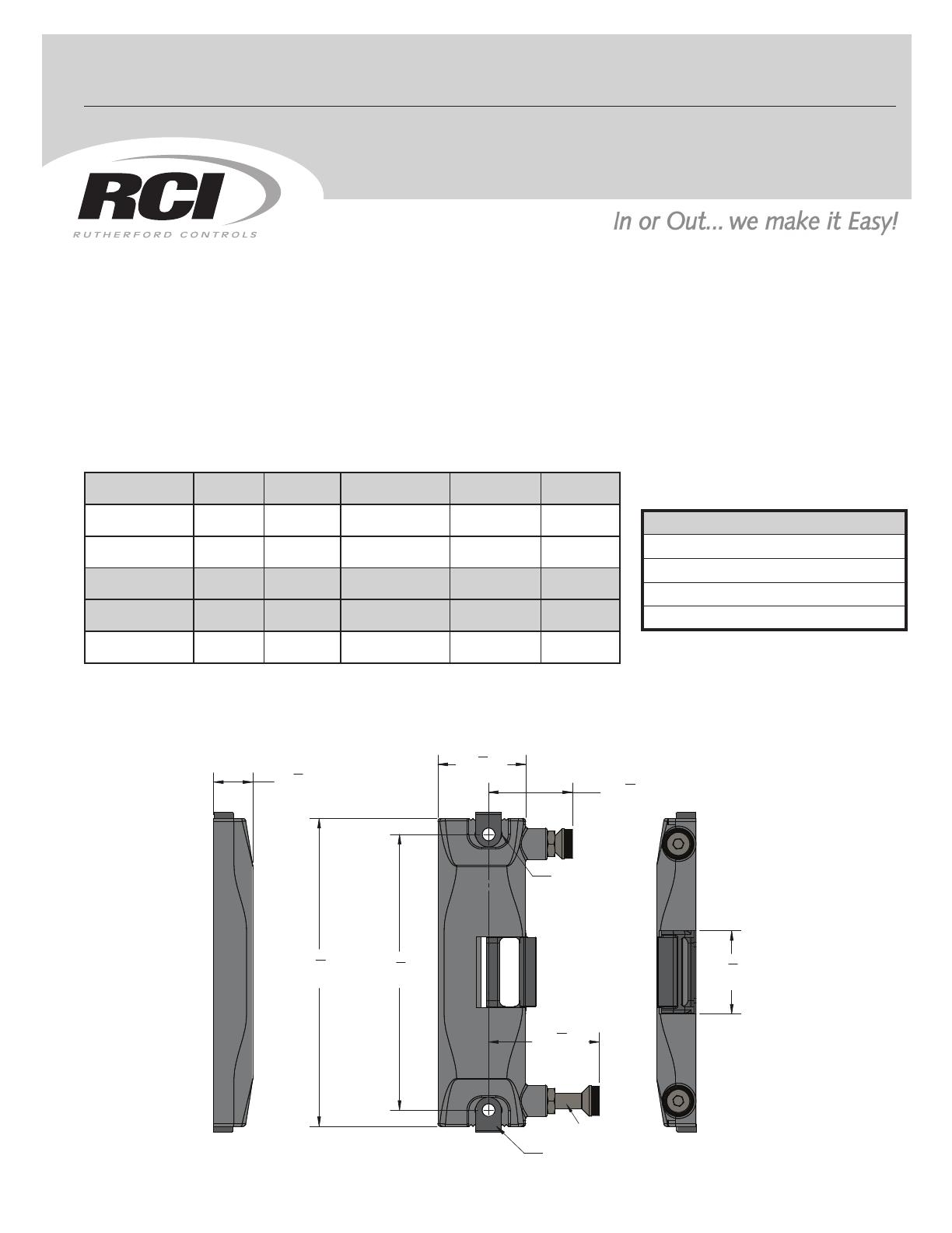
SURFACE MOUNTED VERTICAL ROD STRIKE
Dimensional Details
© 2016 RUTHERFORD CONTROLS INT’L
WWW.RUTHERFORDCONTROLS.COM • PHONE: 1.800.265.6630 • FAX: 1.800.482.9795 • E-MAIL: [email protected]
"2
1
4
(57.0mm)
8
"
(41.5mm)
1
5
HOLES
MOUNTING
HORIZONTAL
ADJUSTMENT
LOCK DOWN
CLAMP
"1
3
4
(44.5mm)
"5
1
2
(139.7mm)
6
1
8
"
(155.6mm)
3
4
"
(19.0mm)
1
5
8
"
(42.0mm)
M8 SCREW
R09/16TG-2
®
UL 294 Performance Ratings:
Access Control Line Security : Level I
Destructive Attack : Level I
Endurance : Level IV
Standby Power : Level I
Instructions
1. Close the door and place the template under the retractable latch.
2. Use projection of latch to align the vertical and horizontal centerline of the strike.
3. Center punch the two mounting holes along with the wire access hole shown on the template.
4. Open the door and remove the template.
5. Make wire connections from the power source to the appropriate wire harness supplied. Use 12VDC wire harness for
12VDC, 12-24VAC or 11-16VAC input power. Use 24VDC wire harness for 24VDC input power only.
NOTE: Overheated or burnt coils caused by incorrect input voltage / wire harness combinations will not be
covered under warranty
6. Drill the wire access hole, and drill and tap the two mounting holes (1/4-20 UNC) according to the template.
7. Mount the strike using the Lock Down clamps and 1/4-20 UNC screws provided. Adjust electric strike if needed until
the roller latch is fully engaged.
8. Adjust the M8 screws along with the nuts provided until the door makes contact with the rubber washer on top of
them, then secure them by tightening the nuts towards the body of the strike.
9. Tighten the mounting screws and check operation. Adjust the projection of the roller latch as required.
© 2016 RUTHERFORD CONTROLS INT’L
WWW.RUTHERFORDCONTROLS.COM • PHONE: 1.800.265.6630 • FAX: 1.800.482.9795 • E-MAIL: [email protected]
Latch Projection
4.00mm Min.
7.80mm Max.
ROLLER LATCH
ROLLER LATCH
Keeper
Keeper
  • Page 1 1
  • Page 2 2

Dormakaba VR165 Vertical Rod Installation guide

Category
Security device components
Type
Installation guide
This manual is also suitable for

Ask a question and I''ll find the answer in the document

Finding information in a document is now easier with AI