Page is loading ...

SE5AP03 for DYFA3045 Printed in USA V1.1
READ THROUGH THIS MANUAL BEFORE STARTING CONSTRUCTION. IT
CONTAINS IMPORTANT INSTRUCTIONS AND WARNINGS CONCERNING THE
ASSEMBLY AND USE OF THIS MODEL.
Entire Contents © Copyright 2007
Instruction Manual
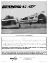
• QUICK BUILDING – IDEAL FOR FUN-SCALE COMPETITION
• 64" WINGSPAN (IMAA Legal)
• SMOOTH-FLYING BIPE – CAPABLE OF SCALE AEROBATICS
WARRANTY
Dynaflite
™
guarantees this kit to be free from defects in both material and workmanship at the
date of purchase. This warranty does not cover any component parts damaged by use or
modification. In no case shall Dynaflite’s liability exceed the original cost of the
purchased kit. Further, Dynaflite reserves the right to change or modify this warranty without
notice. In that Dynaflite has no control over the final assembly or material used for final
assembly, no liability shall be assumed nor accepted for any damage resulting from the use by
the user of the final user-assembled product. By the act of using the user-assembled product,
the user accepts all resulting liability. If the buyer is not prepared to accept the liability
associated with the use of this product, the buyer is advised to return this kit
immediately in new and unused condition to the place of purchase.
™
Wingspan: 64 in [1625mm]
Wing Area: 1440 sq in [93dm
2
]
Weight: 12.0 - 13.5 lb [5440 - 6120g]
Wing Loading: 19.2 - 21.3 oz/sq ft [59 - 65g/dm
2
]
Fuselage Length: 53 in [1345mm]
Engine: .61 - 1.20 cu in [10.0 - 19.5cc] two-stroke, .91 - 1.20 cu in
[15.0 - 19.5cc] four-stroke
Radio: 4-channel, 7 or 8 servos (single or dual elevator servos)

INTRODUCTION ..............................................2
IMAA ..........................................................................3
Scale Competition ....................................................3
SAFETY PRECAUTIONS ..................................3
DECISIONS YOU MUST MAKE ........................4
Radio Equipment ......................................................4
Engine Recommendations ......................................5
Covering & Paint ......................................................5
ADDITIONAL ITEMS REQUIRED......................5
Hardware & Accessories ..........................................5
Adhesives & Building Supplies ..............................6
Covering Tools ..........................................................6
Optional Supplies & Tools ........................................6
Important Building Notes ........................................7
Metric Conversions ..................................................8
Metric/Inch Ruler ......................................................8
DIE DRAWINGS ......................................9 & 10
LABEL THE PARTS ........................................11
BUILD THE TAIL SURFACES ..........................11
BUILD THE WING ..........................................13
Build the Bottom Center Panel ..............................13
Build the Top Center Panel......................................16
Build the Outer Panels ............................................17
Mount the Aileron Servos ......................................20
Build the Wing Tips..................................................21
Join the Wing Panels ..............................................24
BUILD THE FUSELAGE ..................................25
Build the Fuselage Sides ........................................25
Mount the Fuel Tank ................................................29
Install the Strut Mounts ..........................................29
Mount the Engine....................................................31
Build the Top of the Fuselage ................................33
FINAL CONSTRUCTION ................................35
Mount the Bottom Wing ........................................35
Fit the Stab & Fin ....................................................37
Make the Tail Gear Mount ......................................39
Mount the Main Landing Gear ..............................40
Prepare the Wing Struts..........................................41
Mount the Engine Cowls ........................................42
Cover the Model ......................................................43
Painting ....................................................................45
FINAL ASSEMBLY ........................................46
Glue in the Stab & Fin ............................................46
Hinge the Control Surfaces ....................................48
Finish the Wing Struts ............................................48
Finish the Radio Installation ..................................51
Finish the Cockpit ....................................................53
Machine Gun............................................................54
Apply the Decals ....................................................55
GET THE MODEL READY TO FLY ..................55
Check the Control Directions..................................55
Set the Control Throws ..........................................55
Balance the Model (C.G.)........................................56
Balance the Model Laterally ..................................57
PREFLIGHT....................................................57
Identify Your Model ................................................57
Charge the Batteries................................................57
Balance the Propeller ..............................................58
Ground Check ..........................................................58
Range Check ............................................................58
ENGINE SAFETY PRECAUTIONS ..................58
AMA SAFETY CODE (excerpt) ......................59
IMAA SAFETY CODE (excerpt) ....................60
CHECK LIST ..................................................60
FLYING ..........................................................61
Fuel Mixture Adjustments ......................................61
Field Assembly ........................................................62
Takeoff ......................................................................62
Flight ........................................................................62
Landing ....................................................................63
Thank you for purchasing the Dynaflite S.E.5a.
This kit is intended for modelers who desire the
nostalgic appearance and gentle flight
characteristics of a WWI biplane, but don’t wish
to spend hours in the shop working on minute
scale details. Simply by following the
instructions
you’ll end up with a model that very much
represents an S.E.5a featuring the most
important characteristics including exhaust
pipes, wing struts, pilot head rest, wooden tail
gear and simulated radiators. Of course, if you
like to fiddle and spend extra time there’s no
end to the amount of detail you could add on
your own.
For the latest technical updates or manual
corrections to this model visit the web site
listed below and select the Dynaflite S.E.5a. If
there is new technical information or changes to
this kit a “tech notice” box will appear in the
upper left corner of the page.
http://www.dynaflite.com
INTRODUCTION
TABLE OF CONTENTS
2

The Dynaflite S.E.5a is an excellent sport-scale
model. Because it’s a biplane with a wingspan
over 60", it is eligible to fly in IMAA events. The
IMAA (International Miniature Aircraft
Association) is an organization that promotes
non-competitive flying of giant-scale models. If
you plan to attend an IMAA event, contact the
IMAA for a copy of the IMAA Safety Code at
the address or telephone number below.
IMAA
205 S. Hilldale Road
Salina, KS 67401
(913) 823-5569
Though the Dynaflite S.E.5a may not have the
same level of detail as an “all-out” scratch-built
competition model, it is a scale model
nonetheless and is therefore eligible to
compete in the
Fun Scale
class in AMA
competition. This is the perfect place for
beginning scale modelers to “get their feet
wet.” To receive the five points
for scale
documentation, the only proof
required that a
full size aircraft of this type in your
paint/markings scheme did exist is a single
sheet such as a kit box cover from a plastic
model, a photo, or a profile painting, etc. If the
photo is in black and white other written
documentation of color must be provided.
Contact the AMA for a rule book with full
details.
Note: The full-size S.E.5a has a wingspan of
26'-4" [slightly over 8m]. This model has a
wingspan of 64" [1625mm], so the scale is
20.25%, or slightly larger than 1/5 scale. The
model featured on the kit box cover and in this
instruction manual was finished similar to
the
one on the cover of the Squadron
Publication’s
S.E.5a in Action
book (No. 1069).
This book
contains many photographs,
different trim
schemes and documentation that would be
useful for finishing your model and getting to
know more about the full-size S.E.5a.
Another source of photographs, three-view
drawings and scale documentation is:
Bob’s Aircraft Documentation
3114 Yukon Ave
Costa Mesa, CA 92626
Telephone: (714) 979-8058
Fax: (714) 979-7279
e-mail:
www.bobsairdoc.com
1. Your S.E.5a should not be considered a toy,
but rather a sophisticated, working model that
functions very much like a full-size airplane.
Because of its performance capabilities, the
S.E.5a, if not assembled and operated correctly,
could possibly cause injury to yourself or
spectators and damage to property.
2. You must assemble the model according to
the instructions. Do not alter or modify the
model, as doing so may result in an unsafe or
unflyable model. In a few cases the instructions
may differ slightly from the photos. In those
instances the written instructions should be
considered as correct.
3. You must take time to build straight, true
and strong.
4. You must use an R/C radio system that is in
first-class condition, and a correctly sized
engine and components (fuel tank, wheels, etc.)
throughout the building process.
PROTECT YOUR MODEL,
YOURSELF & OTHERS...
FOLLOW THESE IMPORTANT
SAFETY PRECAUTIONS
SCALE COMPETITION
IMAA
3

5. You must correctly install all R/C and other
components so that the model operates
correctly on the ground and in the air.
6. You must check the operation of the model
before every flight to insure that all equipment
is operating and that the model has remained
structurally sound. Be sure to check clevises or
other connectors often and replace them if they
show any signs of wear or fatigue.
7. If you are not already an experienced R/C
pilot, you should fly the model only with the
help of a competent, experienced R/C pilot.
8. While this kit has been flight tested to exceed
normal use, if the plane will be used for
extremely high stress flying, such as aggressive
aerobatics, the modeler is responsible for
taking steps to reinforce the high stress points.
Remember: Take your time and follow the
instructions to end up with a well-built
model that is straight and true.
Before starting to build, compare the
parts in this kit with the Parts List, and
note any missing parts. Also inspect all
parts to make sure they are of acceptable
quality. If any parts are missing, broken or
defective, or if you have any questions
about building or flying this airplane,
please call us at (217) 398-8970, or e-mail
us at pr[email protected]. If
you are contacting us for replacement
parts, please be sure to provide the full kit
name (Dynaflite S.E.5a) and the part
numbers as listed in the Parts List.
You can also check our web site at
www.dynaflite.com for the latest S.E.5a
updates.
If you have not flown this type of model before,
we recommend that you get the assistance of
an experienced pilot in your R/C club for your
first flights. If you’re not a member of a club,
your local hobby shop has information about
clubs in your area whose membership includes
experienced pilots.
In addition to joining an R/C club, we strongly
recommend you join the AMA (Academy of
Model Aeronautics). AMA membership is
required to fly at AMA sanctioned clubs. There
are over 2,500 AMA chartered clubs across the
country. Among other benefits, the AMA
provides insurance to its members who fly at
sanctioned sites and events. Additionally,
training programs and instructors are available
at AMA club sites to help you get started the
right way. Contact the AMA at the address or
toll-free phone number below:
The Dynaflite S.E.5a may be operated with
either seven or eight servos. The elevators are
connected to separate pushrods, but the
pushrods may be linked together and
connected
RADIO EQUIPMENT
DECISIONS YOU MUST
MAKE
Academy of Model
Aeronautics
5151 East Memorial Drive
Muncie, IN 47302
Tele: (800) 435-9262
Fax (765) 741-0057
Or via the Internet at:
http://www.modelaircraft.org
We, as the kit manufacturer, provide you with
a top quality kit and instructions, but
ultimately the quality and flyability of your
finished model depends on how you build it;
therefore, we cannot in any way guarantee
the performance of your completed model,
and no representations are expressed or
implied as to the performance or safety of
your completed model.
4

to one servo, or connected to separate servos. If
powering the S.E.5a with an engine in the
upper end of the recommended range, and/or if
you plan of flying lots of aerobatics with your
S.E.5a, two elevator servos are recommended.
If two servos are used for the elevators, a radio
capable of electronic mixing (so one of the
servos can be “reversed”) must be used, or an
electronic device to make one of the servos
move in the opposite direction will be required.
The Futaba
®
SR-10 Synchronized Servo
Reverser
(FUTM4150) may be used to reverse one of the
servos and is compatible with most popular
radio systems.
As for the type of servos, servos with a
minimum of 50 oz.-in. of torque are
recommended for the elevator(s) and rudder,
while standard servos may be used on the
ailerons and throttle.
Three (3) Hobbico
®
Pro Series
™
“Y” Harnesses
(HCAM2751 for Futaba J connectors) are also
required for the ailerons (one “Y” Harness in
each wing and one inside the fuselage).
A receiver battery with a minimum capacity of
1,000 mAh is also recommended.
Keep in mind that this is a scale model of a WWI
biplane that is intended to fly in a scale-like
manner-planes of that day weren’t capable of
some of the high-stress aerobatic maneuvers
flown today. The Dynaflite S.E.5a flies most
scale-like with engines nearer the bottom of the
recommended size range. Even with the O.S.
®
MAX .91 four-stroke, the model was flown at
reduced throttle settings much of the time. If the
S.E.5a is powered by an engine in the upper
end of the recommended size range prudent
throttle management must be used.
The S.E.5a on the kit box cover was covered
primarily with flat olive drab and flat cream Top
Flite
®
MonoKote
®
film. The white band around
the fuselage was made from white MonoKote
and the rudder was covered with dark red, sky
blue and white MonoKote (scuffed with 600-grit
sandpaper to remove the shine). The plastic
parts (cowl, headrest, etc.) were painted with
olive drab Top Flite LustreKote
®
(TOPR7210). The
wing struts and tail gear mount were stained
with Minwax Special Walnut 224 stain, then
clear-coated with crystal clear LustreKote
(TOPR7200). Below are the order numbers for
full 6' rolls of covering to finish the model like
the one on the kit box cover (only
approximately one foot of dark red, white and
sky blue are required).
Flat Olive Drab (two rolls) – TOPQ0510
Flat Cream (one roll) – TOPQ0512
White – TOPQ0204
Sky Blue – TOPQ0206
Dark Red – TOPQ0218
This is the list of hardware and accessories
used to finish the S.E.5a. Order numbers are
provided in parentheses.
❏
(3) Y-harnesses for ailerons (HCAM2751 for
Futaba)
❏
R/C foam rubber (1/4" [6mm] - HCAQ1000,
or 1/2" [13mm] - HCAQ1050)
❏
10 oz. [300cc] fuel tank (GPMQ4104)
❏
Propeller and spare propellers
❏
3' [900mm] standard silicone fuel tubing
(GPMQ4131)
❏
Fuel filler valve for glow fuel (GPMQ4160)
HARDWARE & ACCESSORIES
ADDITIONAL ITEMS
REQUIRED
COVERING & PAINT
ENGINE RECOMMENDATIONS
5

❏
William’s Brothers #13300 5" [127mm]
Vintage Wheels (WBRQ1133)
❏
1/2" [13mm] double-sided foam mounting
tape (GPMQ4440)
❏
Velcro hook and loop material (for
mounting battery pack, GPMQ4480)
❏
Great Planes long-handle 3/32" hex driver
ball wrench (for wing strut screws,
GPMR8002)
❏
2 oz. [60g] Thin Pro CA (GPMR6003)
❏
2 oz. [60g] Medium Pro CA+ (GPMR6009)
❏
Pro
™
30-minute epoxy (GPMR6047)
❏
Milled fiberglass (GPMR6165) -or-
❏
Microballoons (TOPR1090)
❏
HobbyLite
™
balsa-colored balsa filler
(HCAR3401)
❏
Plan protector (GPMR6167) or wax paper
❏
Threadlocker thread locking cement
(GPMR6060)
❏
Drill bits: 1/16" [1.6mm], 3/32" [2.4mm],
1/8" [3.2mm], 9/64" [3.6mm] (or 1/8"
[3.2mm]), 5/32" [4mm], 3/16" [4.8mm],
13/64" [5.2mm], 1/4" [6.4mm], 17/64"
[6.7mm] (or 1/4" [6.4mm]), #34 (or 17/64"
[6.7mm])
❏
6-32 tap and #36 (or 17/64" 6.7mm]) drill or
Great Planes 6-32 tap and drill set
(GPMR8102)
❏
1/4-20 tap and #7 (or 13/64" [5.2mm]) drill
or Great Planes 1/4-20 tap and drill set
(GPMR8105)
❏
Tap handle (GPMR8120)
❏
Silver solder w/flux (GPMR8070)
❏
Stick-on segmented lead weights
(GPMQ4485)
❏
#1 Hobby knife (HCAR0105)
❏
#11 blades (5-pack, HCAR0211)
❏
#11 blades (100-pack, HCAR0311)
❏
T-pins (small – HCAR5100, medium –
HCAR5150, large – large HCAR5200)
❏
3/16" [4.8mm] K&S brass tube
❏
X-Acto
®
#240 razor saw (XACR1440)
❏
Sanding tools and sandpaper assortment
(see
“Easy-Touch
™
Bar Sander”
section)
❏
21st Century
®
sealing iron (COVR2700)
❏
21st Century iron cover (COVR2702)
❏
21st Century trim seal iron (COVR2750)
Here is a list of optional tools and accessories
mentioned in the manual that will help you
build the S.E.5a.
❏
16" x 36" [410 x 910mm] building board
(GPMR6948)
❏
Robart Super Stand II (ROBP1402)
❏
William’s Brother’s #625 1/4-scale
standard pilot (WBRQ2625)
❏
Acrylic paint and paint brushes for
painting pilot (found at hobby and craft
stores)
❏
William’s Brother’s #161 2" 1/6-scale Lewis
Aircraft machine gun (WBRQ3561)
❏
Fourmost Products #FOR 114 regular
cockpit coaming (FORQ2014)
❏
Masking tape (TOPR8018)
❏
CA activator (2 oz. [57g] spray –
GPMR6035, or 4 oz. [113g] aerosol –
GPMR634)
❏
CA applicator tips (HCAR3780)
❏
CA debonder (GPMR6039)
❏
Denatured alcohol (for epoxy clean up)
❏
Epoxy brushes (6, GPMR8060)
❏
Mixing sticks (50, GPMR8055)
❏
Mixing cups (GPMR8056)
❏
Slot Machine
™
hinge slotting tool (110V,
GPMR4010)
❏
Builder’s Triangle Set (HCAR0480)
❏
Curved-tip canopy scissors for trimming
plastic parts (HCAR0667)
OPTIONAL SUPPLIES
& TOOLS
COVERING TOOLS
ADHESIVES & BUILDING
SUPPLIES
6

❏
D.G. Products Perma-Grit tungsten
carbide flat sanding bar
❏
Heat shrink tubing (for securing servo wire
connections inside wings, GPMM1058)
❏
K & S #801 Kevlar thread (for stab
alignment, K+SR4575)
❏
Switch & Charge Jack Mounting Set
(GPMM1000)
❏ Remote glow plug hookup (Sullivan #M
021
Remote Headlock, MODP1221
❏
Panel Line Pen (TOPQ2510)
❏
Rotary tool such as Dremel
®
Moto-Tool
®
❏
Rotary tool reinforced cut-off wheel
(GPMR8020)
❏
Servo horn drill (HCAR0698)
❏
Hobby Heat
™
micro torch (HCAR0750)
❏
Dead Center
™
engine mount hole locator
(GPMR8130)
❏ AccuThrow
™
deflection gauge
(GPMR2405)
❏
Laser incidence meter (GPMR4020)
❏
Precision Magnetic Prop Balancer
™
(TOPQ5700)
A flat, durable, easy to handle sanding tool is a
necessity for building a well-finished model.
Great Planes makes a complete range of Easy-
Touch Bar Sanders and replaceable Easy-Touch
Adhesive-backed Sandpaper. While building the
S.E.5a, two 5-1/2" [140mm] Bar Sanders and
two 11" [280mm] Bar Sanders equipped with
80-grit and 150-grit Adhesive-backed
Sandpaper were used.
Here’s the complete list of Easy-Touch Bar
Sanders and Adhesive Backed Sandpaper:
5-1/2" [140mm] Bar Sander (GPMR6169)
11" [280mm] Bar Sander (GPMR6170)
22" [560mm] Bar Sander (GPMR6172)
33" [840mm] Bar Sander (GPMR6174)
44" [1120mm] Bar Sander (GPMR6176)
11" [280mm] Contour Multi-Sander
(GPMR6190)
12' [3.66m] rolls of Adhesive-backed sandpaper:
80-grit (GPMR6180)
150-grit (GPMR6183)
180-grit (GPMR6184)
220-grit (GPMR6185)
Assortment pack of 5-1/2" [140mm] strips
(GPMR6189)
We also use Top Flite 320-grit (TOPR8030, 4
sheets) and 400-grit (TOPR8032, 4 sheets) wet-
or-dry sandpaper for finish sanding.
• There are two types of screws used in this
kit:
Sheet metal screws are designated by a
number and a length.
For example #6 x 3/4"
This is a number six screw that is 3/4" long.
IMPORTANT BUILDING
NOTES
7

Machine screws are designated by a number,
threads per inch, and a length.
For example 4-40 x 3/4"
This is a number four screw that is 3/4" long
with forty threads per inch.
• When you see the term
test fit
in the
instructions, it means that you should first
position the part on the assembly without
using any glue, then slightly modify or
custom
fit
the part as necessary for the best fit.
• Whenever the term
glue
is written you
should rely upon your experience to decide
what type of glue to use. When a specific type
of adhesive works best for that step, the
instructions will make a recommendation.
• Whenever just
epoxy
is specified you may
use
either
30-minute (or 45-minute) epoxy
or
6-minute epoxy. When 30-minute epoxy is
specified it is highly recommended that you
use only 30-minute (or 45-minute) epoxy,
because you will need the working time and/or
the additional strength.
• Photos and sketches are placed before
the step they refer to. Frequently you can study
photos in following steps to get another view of
the same parts.
• Not all die-cut parts have a name, or their
complete name stamped on them, so refer to
the die drawings on pages 9 and 10 for
identification. When it's time to remove the
parts from their die sheets, if they are difficult to
remove, do not force them out. Instead, use a
sharp #11 blade to carefully cut the part from
the sheet, then lightly sand the edges to remove
any slivers or irregularities. Save some of the
larger scraps of wood.
• The easiest way to cut balsa sticks is with a
single-edge razor blade or razor saw. Position
the stick over the plan, mark its size, then cut
the part on a piece of scrap wood. A modeling
miter box works well for cutting square corners
and 45° gussets.
8
0" 1" 2" 3" 4" 5" 6"
0 10 20 30 40 50 60 70 80 90 100 110 120 130 140 150
Inch Scale
Metric Scale
METRIC CONVERSIONS
1/64" = .4 mm
1/32" = .8 mm
1/16" = 1.6 mm
3/32" = 2.4 mm
1/8" = 3.2 mm
5/32" = 4.0 mm
3/16" = 4.8 mm
1/4" = 6.4 mm
3/8" = 9.5 mm
1/2" = 12.7 mm
5/8" = 15.9 mm
3/4" = 19.0 mm
1" = 25.4 mm
2" = 50.8 mm
3" = 76.2 mm
6" = 152.4 mm
12" = 304.8 mm
18" = 457.2 mm
21" = 533.4 mm
24" = 609.6 mm
30" = 762.0 mm
36" = 914.4 mm

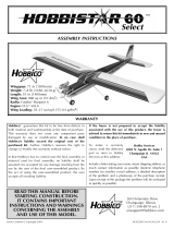
9
Die Drawing

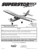
10
Die Drawing

❏
Use the
die drawings
on pages 9 and 10 to
identify and mark the die-cut parts with a
ballpoint pen before removing them from their
die sheets (some, but not all of the parts already
have numbers or names stamped on them).
While building, if a part is difficult to remove
from its die sheet, don’t force it out. Instead, cut
around the part with a hobby knife and a #11
blade. Where necessary, lightly sand the edges
of the part to remove slivers or die-cutting
irregularities. As you proceed, it’s not necessary
to save every scrap of wood, but some of the
larger pieces of wood should be saved.
❏
1. Unroll the fuselage plan. Roll it inside out
so it will lie flat.
❏
2. Position the plan so the fin is over your flat
building board. Cover the plan with Great
Planes Plan Protector or wax paper so glue will
not adhere to the plan.
❏
3. Use medium CA to build the fin from three
3/8" x 1/2" x 30" [9.5 x 13 x 760mm] balsa sticks
and one 1/4" x 3/8" x 18" [6.4 x 9.5 x 460mm]
balsa stick. Use T-pins to hold the sticks down as
you proceed. Note the angles on the ends of
some of the sticks (indicated by the arrows in
the photo) are not cut until the next step. Also
note the 3/32" [2.4mm] vent holes (shown on
the plan) that have been pre drilled through the
sticks to allow air to escape during covering. It’s
easiest to drill these holes before the sticks are
glued into position.
❏
4. Remove the fin from the plan. Cut the rest
of the angles on the sticks that weren’t cut
earlier. Sand both sides of the fin flat and
smooth
and round the tip.
❏
5. Build the rudder using the sticks left over
from the fin plus an additional 3/8" x 1/2" x 30"
[9.5 x 13 x 760mm] balsa stick.
BUILD THE TAIL SURFACES
LABEL THE PARTS
11

❏
6. Reposition the plan so the stab is over the
building board. Don’t forget to cover it with
Plan Protector or wax paper. Use the sticks left
over from the fin and rudder plus four more 3/8"
x 1/2" x 30" [9.5 x 13 x 760mm] balsa sticks and
three more 1/4" x 3/8" x 18" [6.4 x 9.5 x 460mm]
balsa sticks to build the stab and elevators.
❏
7. Use a ballpoint pen to mark centerlines on
the trailing edge of the fin and stab and on the
leading edges of the rudder and elevators.
Hint: Rest the pen on a thin stack of plywood or
cardstock. Adjust the thickness of the stack until
the pen is on-center.
❏
8. Cut twelve 3/4" x 1" [19 x 25mm] hinges
from the 2" x 9" [51 x 230mm] CA hinge strip
supplied with this kit. Snip the corners off so
they go in easier.
❏
9. Use a Great Planes Slot Machine to cut the
hinge slots on the centerlines in the stab and
elevators and in the fin and rudder where
shown on the plan. If you do not have a Slot
Machine, follow the procedure that follows to
cut the hinge slots with a hobby knife and a #11
blade
(or run to the hobby shop and buy a Slot
Machine!).
NOTES ABOUT CA HINGES
This kit is supplied with CA hinge material
consisting of a 3-layer lamination of Mylar
and polyester specially made for hinging
model airplanes. When properly installed,
this type of CA hinge provides the best
combination of strength, durability and easy
installation. We use these hinges on all our
models, but it is essential to install them
correctly. Follow the hinging instructions in
this manual for the best result. The
techniques shown have been developed to
ensure thorough and secure gluing.
12

❏
10. Temporarily join the rudder to the fin and
the elevators to the stab with the hinges. Make
adjustments to the hinge slots where
necessary.
With the control surfaces temporarily joined,
sand the outer edges of all the parts round
(except for where they are hinged).
❏
11. Remove all the hinges. Use a razor plane
followed by a bar sander to shape the leading
edge of the rudder and elevators to a “V” as
shown on the plan.
Set the tail parts aside and proceed to the wing.
❏
1. Roll the wing plan inside out so it will lay
flat. Position the plan so the bottom center
panel is over your flat building board (or cut it
from the wing plan). Cover the plan with Plan
Protector or wax paper so glue will not adhere
to it.
❏
2. Cut a 1/8" x 1/4" x 24" [3.2 x 6.4 x 610mm]
basswood stick into two 12" [305mm] pieces.
BUILD THE BOTTOM
CENTER PANEL
BUILD THE WING
How to cut hinge slots with a hobby knife
When using a hobby knife to cut hinge slots,
one of the most common mistakes made by
modelers is making the slots too tight. This
restricts the flow of CA to the back of the
hinges. Another mistake made when
installing hinges is not using enough glue to
fully secure the hinge over its entire surface
area. This results in hinges that are only
tack
glued
. Follow these steps to cut hinge slots
with a hobby knife:
A. Using the centerline as a guide, cut one of
the hinge slots where shown on the plan with
a #11 blade. Begin by cutting a shallow slit.
Make three or four cuts along the same line,
going slightly deeper each time. As you
proceed, be certain to go straight into the
wood and move the knife from side to side
until the slot is wide enough to accommodate
a hinge.
B. Test fit a hinge into the slot. If the hinge
does not slide into the slot easily, remove the
hinge and reinsert the knife, working the
blade back and forth a few times to provide
more clearance (it’s the back edge of the
blade that does the widening).
C. Cut the rest of the hinge slots the same
way.
13

Use the “crossed-pin” technique to pin the
spars to the plan over the location for the
forward and aft bottom spars.
❏
3. Use a hobby knife and a straightedge to
cut partway through opposite sides of both
die-cut 3/32" [2.4mm] balsa wing ribs R2
between the forward spar notches.
Refer to this photo for the following
six steps.
❏
4. With the cuts made in the previous step
facing outward, glue both R2 ribs and the three
die-cut 1/8" [3.2mm] plywood R1B ribs to the
spars over their location on the plan. Use a
small builder’s triangle to hold the ribs vertical
as you glue. It is especially important that the
outer R2 ribs are vertical.
❏
5. Cut another 1/8" x 1/4" x 24" [3.2 x 6.4 x
610mm] basswood stick into two 9-5/8"
[245mm]
pieces. Glue them into the notches in the top of
the ribs for the forward and aft top spars. The
same as when gluing the ribs to the bottom
spars, use a small builder’s triangle to hold the
ribs–especially the outer ribs–vertical as you
glue.
❏
6. Glue the four die-cut 1/8" [3.2mm] plywood
inner bottom webs (labeled “IBW” on the
part) to the spars and ribs where shown. Glue
the die-cut 1/8" [3.2mm] plywood leading
edge doubler (labeled “LED” on the part) to
the R1B ribs, then cut the sub-leading edge
from a 1/16" x 3/8" x 24" [1.6 x 9.5 x 610mm]
balsa stick and glue it into position. Save the
remainder of the stick for the top center panel.
❏
7. Cut 4" from each of three 3/32" x 3" x 24"
[2.4 x 76 x 610mm] balsa sheets. After doing so,
you will have three 3/32" x 3" x 4" [2.4 x 76 x
102mm] balsa sheets. These are to be used for
shear webs. You will also have three 3/32" x 3"
x 20" [2.4 x 76 x 510mm] balsa sheets to be used
for sheeting the center panel.
❏
8. From one of the 3/32" x 3" x 4" [2.4 x 76 x
102mm] balsa sheets, cut two shear webs for
the front of the forward spars. Note that the
grain is vertical. Glue the shear webs into
position.
❏
9. Remove the bottom inner panel from the
plan. Use a bar sander to sand off any glue
bumps or uneven surfaces from the bottom of
the panel.
❏
10. Using one of the die-cut 3/32" [2.4mm]
balsa center panel trailing edges (labeled
14

“CTE”) as a pattern, make an additional center
panel trailing edge from a 3/32" x 3" x 24" [2.4 x
76 x 610mm] balsa sheet. Save the remainder of
the sheet for the top center panel.
❏
11. Make the top and bottom skins for
sheeting the center panel from the three 3/32" x
3" x 20" [2.4 x 76 x 510mm] balsa sheets you cut
earlier and the center panel trailing edges.
Make the sheets slightly oversize to allow for
trimming later.
❏
12. Working over a flat surface, glue the
center panel structure to the skin that has the
harder, die-cut center panel trailing edge.
❏ 13. Cut out the bottom sheeting to
accommodate
the grooved 1/2" x 3/4" x 5-3/8" [12.7 x 19.1 x
137mm] basswood aft landing gear block.
Note the difference between the aft and the
forward landing gear blocks; the groove in the
forward landing gear block is centered, while
the groove in the aft landing gear block is not
centered. Use a bar sander to taper the trailing
edge of the sheeting using the ribs as a guide.
❏
14. Use a bar sander to lightly sand the top of
the center panel so all the ribs and spars are
even. Also be certain to bevel the top of the sub
leading edge to match the angle of the ribs.
❏
15. Sheet the top of the center panel with the
other skin. After the glue dries, sand the spars
15

and sheeting even with the ends. Sand the front
of the sheeting even with the sub leading edge.
❏
16. Cut the rest of the way through the lines
in the ribs on both ends of the center panel and
remove the balsa between the spars. Set the
bottom center panel aside.
❏
17. Cut the center panel leading edge
slightly longer than required from a 1/4" x 5/8" x
24" [6.4 x 15.9 x 610mm] balsa stick (save the
remainder of the stick for the top center panel).
Glue the leading edge to the front of the center
panel. Sand the ends and top of the leading
edge even with the center panel, but do not
round the leading edge until instructed to do
so.
That’s it for the bottom center panel. Set it aside
and work on the top center panel.
❏
1. Position the plan so the top center panel
is over your flat building board (or cut it from
the wing plan) and cover it with Plan Protector
or wax paper.
❏
2. The same as was done for the ribs on the
ends of the bottom center panel, cut partway
through opposite sides of both die-cut 3/32"
[2.4mm] balsa wing ribs R2 for the ends of the
top center panel between the forward spar
notches.
Be certain to refer to the wing plan while
performing step 3.
❏
3. Make the rib assemblies for both ends of
the top center panel as shown on the plan by
gluing together the die-cut 3/32" [2.4mm] balsa
ribs R2, the die-cut 1/16" plywood ribs R2B and
the die-cut 1/8" [3.2mm] plywood ribs R2T1. Be
certain to make a right and a left.
❏
4. Build the top center panel the same as
the bottom center panel. After gluing in the die-
cut 1/8" [3.2mm] plywood inner top webs
(ITW) add the triangle stock reinforcements cut
from the 3/8" x 17-7/8" [9.5 x 455mm] balsa
tri-stock. Make another center panel trailing
BUILD THE TOP
CENTER PANEL
16

edge using the 3/32" x 3" [2.4 x 75mm] balsa
sheet left over from making the first center
panel trailing edge for the bottom center panel.
Make the skins and save the leftover pieces for
shear webs. Glue the top center panel to the
bottom skin, add the balsa shear webs, then
glue the top skin to the panel. Sand the ends of
the sheeting even with the ribs and sub leading
edge, then cut out the ribs on the ends of the
panel between the spars. Add the leading edge
cut from the 1/4" x 5/8" [6.4 x 15.9mm] balsa
stick left over from the leading edge on the
bottom center panel, then sand to match the
shape of the ribs. Set the top center panel aside.
Note: All four outer panels are nearly identical.
The only differences are that, obviously, there
are two rights and two lefts. The only difference
between the top and bottom panels is the 1/16"
[1.6mm] plywood rib assemblies at R4 where
the wing struts connect.
Start with the left, bottom outer panel first.
❏ ❏ ❏ ❏
1. Position the left outer wing panel
plan over your flat building board and cover it
with wax paper or Plan Protector.
❏ ❏ ❏ ❏
2. Referring to the illustrations near
the leading edge of the left panel on the wing
plan, use medium CA to glue together the die-
cut 1/8" [3.2mm] plywood rib R4A, the die-cut
1/16" plywood rib R4B and the die-cut 3/32"
[2.4mm] balsa rib R4. Be certain you are
looking at the correct illustration for the wing
panel you are working on (top or bottom).
Refer to this photo for the following
six steps.
❏ ❏ ❏ ❏
3. Cut the forward spar 1/8" [3mm]
longer than shown on the plan from a 1/8" x 1/4"
x 24" [3.2 x 6.4 x 610mm] basswood stick. Cut
the aft spar 1/8" [3mm] longer than shown on
the plan from a 1/8" x 1/4" x 30" [3.2 x 6.4 x
760mm] basswood stick.
❏ ❏ ❏ ❏
4. Cut the bottom leading edge
sheet 1/8" [3mm] longer than shown on the
plan from a 3/32" x 3" x 24" [2.4 x 76mm x
610mm] balsa sheet.
❏ ❏ ❏ ❏
5. Glue the forward spar to the top of
the leading edge sheet along the aft edge. Pin
the spar and sheeting to the plan.
❏ ❏ ❏ ❏
6. Cut 4-1/2" [115mm] from a 3/32" x
4" x 30" [2.4 x 100 x 760mm] balsa sheet. Add
the 4-1/2" [115mm] sheet to the stack of sheets
you’ve been saving for shear webs.
❏ ❏ ❏ ❏
7. Cut the 25-1/2" [650mm] sheet from
the previous step into two 1-1/2" [38mm] wide
strips to make the trailing edge sheets. The
same as was done for the leading edge sheet,
cut the trailing edge sheet 1/8" [3mm] longer
than shown and pin to the plan. Save the other
1-1/2" [38mm] wide strip for the top.
BUILD THE OUTER PANELS
17

❏ ❏ ❏ ❏
8. Cut the bottom aileron spar from
a 1/8" x 1/4" x 24" [3.2 x 6.4 x 610mm] basswood
stick as shown on the plan, then pin it over its
location. Save the remainder of the stick for
the top.
❏ ❏ ❏ ❏
9. Glue all the ribs except for rib R3
at the root of the panel and rib R6 at the
tip of the panel to the spars and sheeting.
❏ ❏ ❏ ❏
10. Cut the cap strips that go under
rib R6 from a 3/32" x 3/8" x 24" [2.4 x 9.5 x
610mm] balsa stick, then glue them into
position. Glue rib R6 to the assembly.
❏ ❏ ❏ ❏
11. The same as was done for the ribs
on the ends of the center panels, use a hobby
knife and a straightedge to cut partway through
the outside of the remaining rib R3 that goes on
the end of the outer panel you are working on.
Refer to this photo for the following
two steps.
❏ ❏ ❏ ❏
12. Without using any glue, add the
following parts to the assembly:
• Rib R3 that goes on the root end of the panel.
• The top, forward spar cut from a 1/8" x 1/4" x
24" [3.2 x 6.4 x 610mm] basswood stick.
• The top, aft spar cut from a 1/8" x 1/4" x 30"
[3.2 x 6.4 x 760mm] basswood stick.
• The die-cut 1/8" [3.2mm] plywood outer
webs (OW) that go on the forward spars.
❏ ❏ ❏ ❏
13. Using the die-cut 1/8" [3.2mm]
plywood dihedral gauge (DG) and the outer
webs to set rib R3 at the correct angle, glue rib
R3 to the bottom spars and sheeting only.
❏ ❏ ❏ ❏
14. Glue the top spars to all the ribs.
Glue the outer webs to the spars and ribs. Note
that the top of the outer web on the back of the
spars is even with the top spar.
18

Refer to this photo for the following
three steps.
❏ ❏ ❏ ❏
15. Cut the top aileron spar from the
remainder of the 1/8" x 1/4" x 24" [3.2 x 6.4 x
610mm] basswood stick used for the bottom
aileron spar, then glue it into position.
❏ ❏ ❏ ❏
16. Cut the sub-leading edge from a
1/16" x 3/8" x 24" [1.6 x 6.5 x 610mm] balsa stick,
then glue it into position.
❏ ❏ ❏ ❏
17. Since the plan you are working
over is covered by the structure, refer to the
other outer panel plan you are not working over
to view the shear webs. Cut the shear webs
from two of the 3/32" x 3" x 4" [2.4 x 76 x
100mm] balsa sheets leftover from making the
center panel skins. Remove any T-pins that are
in the way, then glue the shear webs to the front
of the forward spars. Note that the grain on the
shear webs is vertical.
❏ ❏ ❏ ❏
18. Use a bar sander to sand the sub
leading edge to match the angle on the top of
the ribs.
Refer to this photo for the following
four steps.
❏ ❏ ❏ ❏
19. Cut the top leading edge sheet
from a 3/32" x 3" x 24" [2.4 x 76 x 610mm] balsa
sheet. Glue the sheet into position.
❏ ❏ ❏ ❏
20. Remove the outer panel from the
building board. The same as was done on the
center panel trailing edges, taper the outer
panel trailing edge to accommodate the top
trailing edge sheet. Glue the top trailing edge
sheet into position.
❏ ❏ ❏ ❏
21. Cut the cap strips that go over rib
R6 at the wing tip from the remainder of 3/32" x
3/8" balsa stick used for the cap strips on the
bottom of the wing. Glue the cap strips into
position.
❏ ❏ ❏ ❏
22. Use a bar sander to sand the
sheeting, spars and cap strips even with the
ribs on both ends of the outer panel.
❏ ❏ ❏ ❏
23. Cut the leading edge from a 1/4"
x 5/8" x 24" [6.4 x 16 x 610mm] balsa stick, then
glue it into position. Sand the leading edge to
match the shape of the outer panel, but do not
round until instructed to do so.
19

❏ ❏ ❏ ❏
24. Repeat the same steps to build the
left top panel, then switch to the other plan
and build both right panels. Be certain to
refer to the illustrations depicting which
R4 assemblies to use for the panel you are
working on. Hint: Use a thick magic marker to
put a bold “X” through the illustration of the
R4 rib assembly already completed, so you do
not inadvertently build the same one.
The same as we’ve been doing all along, start
with the left, bottom outer panel.
❏ ❏ ❏ ❏
1. Cut the servo hatch rails as
shown on the plan from the 1/8" x 1/2" x 18" [3.2
x 12.7 x 460mm] basswood stick, then glue
them into position. Save the remainder of the
stick for the servo hatch rails for the top panel.
❏ ❏ ❏ ❏ 2. Place a die-cut 1/8" [3.2mm]
plywood
servo hatch (HC) over the rails as shown on
the plan. Drill 1/16" [1.6mm] holes through the
hatch and the rails.
❏ ❏ ❏ ❏
3. Enlarge the holes in the hatch
only with a 3/32" [2.4mm] drill. Use a small
countersink bit or Dremel #178 cutting bit to
countersink the holes in the hatch for the #2 x
3/8" [9.5mm] flat-head screws.
❏ ❏ ❏ ❏
4. Mount the hatch with four #2 x 3/8"
[9.5mm] flat-head screws. Cut the cap strips
for the edges of the hatch from a 3/32" x 3/16" x
MOUNT THE AILERON SERVOS
20
/