Page is loading ...

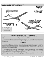
• Learn to fly low-wings with AWARFease!
• Quick to build...flight-ready in just 16-20 hours
• Stable at low speeds—acrobatic at full throttle
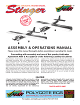
Features like this easy-access
engine positioning will make
BrightStar maintenance fast
and simple.
You'll quickly make a successful step up to flying low-wings with your BrightStar 40 AWARE Its
90% prebuilt construction gets you out of the workshop and onto the flight line in only a matter
of hours. Then you can begin exploring the exciting acrobatic possibilities in the BrightStar's
low-mounted wing...without leaving behind the reasssuring durability and low-speed stability
of your basic trainer.
Easy as 1,2,3
Entire
Contents
©
Copyright
1996
HCAZ3077
V
1.0

Y
ou're about to build in just days what took aviation
pioneers years - a powered machine that flies. Specially
created for you and other first-time radio control modelers,
Hobbico's BrightStar offers nearly all the excitement of
piloting a real airplane...and develops skills that will take you
anywhere you want in your new hobby.
Take a moment now to match the box contents with the
items listed here. Following the BrightStar assembly
instructions will be quite easy if you identify and organize
the parts before you begin.
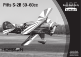
Engine Mounting Parts
Part # Quantity
43 6-32 x 3/4" machine screw.................4
44 #6 washers.......................................... 4
50 Wire pushrods....................................2
57 Pushrod guide tubes...........................2
59 #6 x 3/4" sheet metal screw................4
Tail Assembly
Please take your time and read through the instruction
manual before starting to build your new airplane. If
you have any questions, please feel free to give us a call
at (217) 398-8970. We hope you enjoy building and flying
the BrightStar 40.
Wing Assembly
Part# Quantity
1 Right
wing
with
aileron.............................
1
2 Left
wing
with
aileron...............................1
7 Plywood wing joiners................................3
19
Wing
center tape
.......................................1
21
Aileron
servo tray
......................................1
23 Aileron control horns................................2
24
Threaded
aileron
pushrods
......................2
25 Clevises......................................................2
28
Clear
clevis
retaining
tube........................
1
Part # Quantity
4 Horizontal stab and elevator.........1
5 Vertical fin and rudder...................1
25 Clevises ...........................................2
26 Control horns .................................2
28 Clear clevis retaining tube.............1
36 Dowel pushrods .............................2
46 2x15mm machine screws..............4
60 Dorsal fin ........................................1
61 Dorsal fin covering.........................1
2

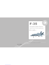
Landing Gear
Part# Quantity
10 Main landing gear strut .............2
11
Nose gear
strut
...........................1
22 Wheel Pant
.................................3
27 Plastic steering
arm
...................1
29 Landing gear strap (Nylon) .......4
31 Wheel ..........................................3
32 Wheel collar / 3x5mm screw.....7
47 2.5xl0mm sheet metal screw....4
58 Pushrod connector ....................2
62 Landing gear strap (Metal)........3
* Sketches shown are not
actual size or to scale.
Inch Scale
Fuselage & Parts
Part # Quantity
3 Fuselage .................................1
8 Wing mounting dowel...........2
20 Servo tray ...............................1
40 Stabilizer mounting base......l
51 Spinner...................................1
52 Servo tray support.................1
Fuel Tank & Parts
Part # Quantity
12 Fuel tank ..............................................1
13
Rubber tank
stopper
...........................1
14
Fuel pick-up weight
(clunk)
...............1
15 Plastic stopper disk
(one large and
one
small)
...................2
16 Aluminum fuel tubing
(one short and two long)
....................3
17
3xl8mm
sheet metal screw
................1
18
Silicone fuel
line..................................1
33 Foam tank collar..................................1
3

Glues
Choose a high quality 6-minute and 30-minute epoxy, such
as Great Planes* Pro- Epoxy, which has been formulated
especially for R/C model building. Pro Epoxies offer a strong
bond and a variety of curing times suited for every step of
assembly. You'll also need a 1 oz. bottle of thin and a 1 oz.
bottle of medium CA (Cyanoacrylate), plus rubbing alcohol
for easy epoxy cleanup.
Hardware
Tools and accessories required for assembly
include a hobby knife, small and large Phillips
screwdrivers, needle nose pliers, drill with
1/16", 11/64", 5/64", 3/32", 5/32" and 3/16"
bits, ruler, #64 rubber bands, one foot of
medium fuel tubing and petroleum jelly
Model Engine
Power your BrightStar with any high-quality,
.40 - .46 size model engine. The O.S. .40 LA is a
fine engine for this plane. Look for features such
as easy break-in, easy starting, efficient
carburetion and low maintenance. Check the
manufacturer's recommendations for propellers
to use with your engine.
Radio Equipment
To control your BrightStar's "flight path," you'll need a 1991
legal 4-channel aircraft radio system with four standard
servos. Many 4-channel radios include just three. You may
need to purchase the fourth separately. Hobbico Command
servos are available singularly and will work great for this
plane. The servos, battery pack and radio receiver will be
mounted onboard your model and need to be cushioned
from jolts and vibration. Half-inch thick foam rubber sheets
(HCAQ1050) are available for this purpose.
Getting Ready for Flight
Your Hobbico BrightStar can be ready for takeoff in as little as 16-20 hours.
Your hobby dealer or flying instructor (see next page) can help you decide what
accessories you'll need for flight. Most are one-time-only purchases - like a
glow plug igniter (see glossary), fuel pump, and "chicken stick" or electric
starter. You will also need to obtain model glow fuel. Use glow fuel with a
10-15% nitro content to keep your engine performing at its peak.
General Items Required
Mixing Sticks (GPMR8055)
Epoxy Mixing Cups
Clothespins
Foam Rubber (HCAQ1050)
String
Felt-tip Pen
Easy-Touch" Bar Sander
(GPMR6170)
150-grit sandpaper
(GPMR6183)
Adjustable Wrench
Masking Tape
Medium 3/32" Fuel Tubing
(GPMQ4131)
Paper Towels
T-pins
Wire Cutter
Epoxy Brush
Steel File
Wax Paper
4

If you're a beginner, the best way
to begin flying your BrightStar is
with an experienced R/C pilot or
flying instructor at your side. You'll
learn faster and avoid risking your
model before you're truly ready
to solo.
Where do you find an instructor?
Ask at your local hobby shop.
They'll have information about
flying clubs in your area whose
membership includes qualified
instructors. You should also join the
Academy of Model Aeronautics
(AMA), a 165,000 member-strong
national organization with more
than 2,300 chartered clubs across
the country. Through any one of
them, instructor training programs
are available. Contact the AMA at
the address or phone number
below.
Academy of Model Aeronautics
5151 East Memorial Drive
Muncie, IN 47302-9252
(800)435-9262
Fax(317)741-0057
Before you fly:
1. Make sure that no other fliers are using your
radio frequency.
2. Your radio transmitter must be the FIRST thing you
turn ON, and the LAST thing you turn OFF.
3. Double check all control surfaces, making sure they arc
secure and move in the proper direction.
4. Make sure that the transmitter & receiver batteries are
fully charged.
Fuel storage and care:
1. Do not smoke near your engine or fuel.
2. Store all engine fuel in a safe, cool, dry place, away
from children and pets. Model fuel will evaporate, so
make sure that you always store it with the
cap secure.
When starting and running your engine:
1. Always wear safety glasses.
2. Make certain that your glow plug clip is securely
attached to the glow plug and cannot pop off,
possibly falling into the spinning propeller.
3. Use a "chicken stick" or electric starter to start the
engine - NOT your fingers.
4. Make sure that the wires from your starter and glow
plug clip cannot become tangled with the spinning
propeller.
5. Do not stand at the side of the propeller when you
start or run the engine. Even at idle speed, the
spinning propeller will be nearly invisible.
6. If any engine adjustments are necessary, approach
the engine only from behind the spinning propeller.
90-Day Limited Warranty
If you, as the original owner of this model, discover a defect in parts
or workmanship within 90 days of purchase, Hobbico will repair or replace it, at
the option of our authorized U S repair facility, Hobby
Services, without charge Our liability does not include cost of shipping to us
However, Hobby Services will pay shipping expenses to return your model to you
You must provide proof of purchase, such as your original purchase invoice or
receipt, for your model's warranty to be honored
This warranty does not apply to damage or defects caused by misuse or
improper assembly, service or shipment. Modifications, alterations or repair by
anyone other than Hobby Services voids this warranty We are sorry, but we
cannot be responsible for crash damage and/or resulting loss of kits, engines,
accessories, etc
Repair Service
Your BrightStar 40 must be returned directly to Hobby Services for warranty
work The address is Hobby Services, Attn Service Department, 1610 Interstate
Drive, Champaign, IL 61821-1067 Phone (217) 398-0007, or for product
information and technical support please contact us at (217) 398-8970
Please follow the instructions below when returning your model This will
help our experienced technicians to repair and return It as quickly
as possible
1 ALWAYS return your entire system, including airplane and radio.
2 Disconnect the receiver battery switch harness and make sure that the
transmitter is turned off Disconnect all batteries and drain all fuel
3 Include a list of all items returned and a THOROUGH, written explanation
of the problem and service needed If you expect the repair to be covered
under warranty, also include your proof of purchase
4 Include your full return address and a phone number where you can be
reached during the day
If your model is past the 90-day warranty period or is excluded from warranty
coverage, you can still receive repair service through Hobby Services at a
nominal cost Repair charges and postage may be prepaid or billed COD
Additional postage charges will be applied for non-warranty returns All repairs
shipped outside the United States must be prepaid in U S funds only
All pictures, descriptions and specifications found in this instruction manual
and on the product package are subject to change without notice
5

Special Note:
You should charge your radio system before starting to
build. Following the manufacturer's directions, connect
your transmitter and receiver batteries to the system's
charger. This way the radio will be ready when it is time
to install and test the components.
Prepare the wing joiners
both sides of one of the wing joiners. Sandwich this
coated joiner between the remaining two. Make sure
that the centerlines drawn in step 1 are visable on both
sides of the assembly. Quickly proceed through the
following steps (3 and 4) before the glue cures.
Remove the excess epoxy
D 1. Locate the three 1/8" (3mm) die-cut plywood
wing joiners. Arrange the "V'-shaped joiners in the
same orientation as they will be glued together. Sand
off any bumps from the edges. Draw a centerline on
two of the joiners as shown.
D 3. Excess epoxy will squeeze out of the seams
between the joiners and must be removed before the
epoxy is allowed to cure. Use a paper towel and
rubbing alcohol to remove the excess epoxy.
Glue the wing joiners
Note: Please read steps 2 through 4 before mixing epoxy.
D 2. Mix approximately 1/4 oz. (7.5ml) of 30-minute
epoxy using a mixing stick and a cup. Using a mixing
stick or epoxy brush, apply an even coat of epoxy on
Clamp the wing joiner
D 4. Use clothespins to clamp the wing Joiners firmly
together. If any more epoxy squeezes out, remove it
using a paper towel. Make sure the joiners are evenly
lined up with each other. Set the joiner assembly aside
until the epoxy has fully cured.
6

Even the edges
D 5. Using a bar sander or similar tool, sand the wing
roots so they will fit together with no gaps. Do not sand
too much or the dihedral angle could change.
Mark the wing servo cavity
D 6. Mark the aileron servo location on both wing
panels using a felt-tip pen. Using a hobby knife, cut an
opening into both panels following the lines you
just drew.
wing joiner will not fit in the cavity, lightly sand any
excess epoxy or uneven surfaces from the joiner edges,
sides and ends.
Caution: A snug fit is desirable between the joiner and
the wing cavity. Do not sand excessively.
Viewing the wing dihedral
D 8. Pay close attention to the orientation of the wing
joiner in relation to the wing panel, creating the
dihedral angle as shown. Test fit the wing panels
together. They should fit flush against each other
without gaps.
Note!
When performing the following steps, be sure
to use a sufficient amount of epoxy to form a complete
and solid bond between the plywood wing joiner and
the two wing halves. This is the most important glue
joint in the entire airplane.
Please read through the following three steps before
mixing any epoxy. You must complete these steps
within 20 minutes from the time you mix the epoxy.
Glue the joiner
Test fit the wing joiner
D 7. Test fit the wing joiner in both wing panels by
sliding the joiner into the joiner cavity in the wing. The
joiner should slide in snugly up to the centerline. If the
D 9. Mix 3/4 oz. (22ml) of 30-minute epoxy. Use a
mixing stick or epoxy brush to apply epoxy to all four
sides of the joiner cavity. Insert the joiner into the
cavity up to the centerline marked on the joiner plate.
Be sure you are installing the joiner correctly. Quickly
proceed to the next step.
7

Apply epoxy to the wing root rib Test fit the aileron servo
D 10. Apply epoxy inside the joiner cavity of the
remaining wing panel. Next, coat the wing root ribs on
both panels. Quickly proceed to the next step.
Join the wing halves
D 11. Assemble the two wing halves with the tightest
seam possible. No gaps should be showing between
the two wing halves. Clean any excess epoxy from the
outside of the wing using a paper towel dampened
with rubbing alcohol. Use several strips of masking
tape on both sides to hold the wing halves tightly
together. Let the epoxy fully cure before continuing.
D 13. Test fit the aileron servo into the servo tray and
the hole in the top of the wing. Enlarge either hole, if
needed, with a hobby knife or a fine-toothed file until a
proper fit is achieved. The plywood tray should not
actually contact the the sides of the servo. Leave a
1/64" gap all the way around. Remove the servo. The
servo should not touch any of the wing surface.
Install the servo tray
Trim the covering
D 12. Hold the plywood aileron servo tray over the
hole in the top of the wing. Trace the outside of the tray
with a felt-tip pen and then remove the tray from the
wing. Carefully remove the covering within the lines
using a new #11 blade in a hobby knife, being careful
not to cut into the balsa wing sheeting.
D 14. Mix l/8oz. (3.5ml) of 6-minute epoxy to glue the
servo tray to the top side of the wing. Attach the servo
tray to the top of the wing. After the epoxy has cured,
cut a small notch in the servo tray to allow the servo
lead to pass through.
Apply the wing center tape
D 15. Starting at the front of the aileron servo tray,
apply the 1/2" (12.5mm) white wing center tape
8

completely around the wing over the joint. A small
amount of pressure should be applied to make a
smooth seam.
Check the aileron hinge
D 16. Gently tug on each of the ailerons at each hinge
location. If any of the hinges are loose, reglue them as
described here. First, flex the surface all the way one
direction (DO NOT REMOVE THE AILERON).
Install the aileron control horns
D 17. Thread the aileron control horns onto the torque
rods until there is 3/4" (19mm) of torque rod between
the wing and control horns.
Assemble the pushrods
Apply 5 drops of thin CA onto each hinge.
NOTE: Do not use CA accelerator as the CA must
"wick" into the slot. Use a paper towel to absorb any
excess glue. Wait a few minutes for the glue to cure,
then flex the surface the other direction and glue the
other side of the hinges in the same manner. Finally,
flex the surface back and forth several times to free up
the aileron.
D 18. Locate two plastic clevises and two 8 (203mm)
aileron pushrods. Thread the clevises onto the
threaded end of the pushrods until the rod protrudes
between the clevis forks 1/16".
Install the pushrods
D 19. Attach the pushrods to the aileron control horns.
Press the forks of the clevis together until they snap
into place.
9

Securing the aileron pushrods Install the wing mounting dowels
D 20. Locate the 1/4" (6.5mm) diameter clear
retaining tube and cut two 1/4" (6.5mm) pieces. Slide
one piece onto each clevis to secure the connection
between the clevis and the horn.
This concludes the wing assembly for now. Tape the
pushrods to the wing to keep them in place until you
install the servo.
D 2. Insert both wing mounting dowels so they
protrude an equal distance on both sides. Mix 1/4oz.
(7.4ml) of 30-minute epoxy. Apply glue around the
dowels next to the fuselage and slide them in and out
to help force the glue into the holes. Using a paper
towel, spread the excess glue around the ends of the
dowels. This will fuelproof and add strength to the
wood. From the inside of the fuselage, apply more
epoxy around the dowels where they meet the sides of
the fuselage. These wing dowels will be used as anchors
for rubber bands to hold the wing in place. Wipe off all
excess epoxy with a paper towel and rubbing alcohol.
Locate the wing dowel holes
D 1. Locate the four round holes (two on each side of
the fuselage, see photo below for reference) and
remove the covering over each hole.
Caution: Do not cut out the rectangular holes in the
side of the fuselage.
Locate the stabilizer slot
D 3. Locate the horizontal stabilizer slot under the
covering on the tail section of the fuselage by pressing
lightly with your finger. The slot is located on both
sides of the tail. Using a hobby knife, carefully remove
the covering, exposing the slots.
NOTE: Do not cut into the wood around the slot.
10

Install the plywood stabilizer mount Locate the vertical fin slot
D 4. Locate the 1/8" (3mm) plywood stabilizer
mounting base and test fit it into the bottom of the
horizontal stabilizer slot. Lightly sand the base if
necessary to obtain a good fit. Remove the base from
the fuselage.
D 7. Using your finger, locate the vertical fin slot on
the top of the fuselage. Remove the covering with a
hobby knife.
Check the rudder and elevator hinges
Glue the mount In place
D 5. Mix l/8oz. (3 5ml) of 30-minute epoxy. Using a
mixing stick, apply a generous amount of epoxy into
the slot and position the stabilizer mounting base
firmly in position. Remove any excess epoxy that
remains on the top of the stabilizer base and on the
outside of the fuselage with a paper towel and alcohol.
Remove the tail post
D 6. The balsa tail post is located at the rear of the
fuselage, behind the horizontal stabilizer slot. This post
was left for manufacturing alignment. The post must
be removed in order to insert the horizontal stabilizer.
Using a sharp hobby knife or razor saw, cut the post
even with the slot as shown in the picture.
D 8. Gently tug on the rudder and elevator at each
hinge location. If any of the hinges are loose, reglue
them as described here: First, flex the control surface
all the way one direction (DO NOT REMOVE THE
CONTROL SURFACE).
Apply 5 drops of thin CA onto each hinge. Use a paper
towel to absorb the excess glue. Wait a few minutes for
the glue to cure, then flex the surface the other direction
and glue the other side of the hinges. Finally, flex the
surface back and forth several times to free it up.
NOTE: Do not use accelerator on the hinges.
11

Mark the centerline Align the stabilizer with the fuse
D 9. On the top surface of the horizontal stabilizer,
measure to find the exact center from side to side.
Draw a "centerline" using a felt-tip pen. Next, extend
that line onto the trailing edge, in the hinge gap, as
shown. (DO NOT MARK ON THE ELEVATOR.)
EQUAL MEASUREMENTS
D 11. Attach a piece of string with a T-pin to the center
of the fuselage as shown. Hold the string to one corner
of the horizontal stabilizer. The distance from the pin
to the horizontal stabilizer must be exactly the same to
both corners.
Mark the stabilizer location
Align the stabilizer with the wing
(DO NOT USE GLUE IN THIS STEP)
D 10. Insert the stabilizer into the horizontal stabilizer
slot so it is centered in the fuselage (A). Place the wing
onto the fuselage and secure it with two rubber bands
view the plane from the rear to check for proper
alignment. The stabilizer should be parallel with the
wing (B). If not, sand the high side of the stabilizer
mounting plate a little at a time until correct.
D 12. With the stabilizer properly aligned, use a felt-tip
pen to trace a line around the tail of the airplane on the
top and bottom of the horizontal stabilizer.
Remove the center covering
D 13. Remove the stabilizer and draw two additional
lines, on the top and bottom, 1/16" inside the lines
12

drawn in the previous step. Next, carefully cut through
the covering using a new #11 knife blade at the inside
lines and remove the covering from the center. Do not
cut the wood under the covering! This would seriously
weaken the stabilizer and could easily cause the
stabilizer to break in flight. If the stab breaks the plane
may crash, so be very careful when you make this cut.
If the covering is not removed from the stabilizer a
proper bond cannot be achieved.
Install the Dorsal Fin
Install the stabilizer
D 14. Mix l/4oz. (7.5ml) of 30-minute epoxy. Using a
mixing stick, place epoxy inside the horizontal stabilizer
slot on all sides including the horizontal stabilizer
mount. Place more epoxy onto the bottom and top of
the stabilizer where you removed the covering. Insert
the stabilizer from the rear and adjust the alignment.
Wipe off any epoxy that squeezes out using a paper
towel dampened with rubbing alcohol. Recheck the
alignment, several times while the epoxy cures.
Install the vertical fin
90°
D 16. Locate the precut dorsal fin and decal. Apply the
decal to the dorsal fin, starting at the top and working
the decal down the sides. Trim any of the excess decal
so that it doesn't hang from the bottom of the filler.
Carefully trim away the covering from the fuselage
where the filer will be positioned. Glue the filler in
place using Medium CA.
Cut the rudder pushrod exit
D 17. The precut rudder pushrod exit hole is located
on top of the fuselage on the left side of the fin. Use a
hobby knife to remove the covering from the rudder
pushrod exit hole.
Cut the elevator exit
D 15. Test fit the vertical fin into the slot in the top of
the fuselage. Sand the edges of the slot if necessary for
a snug fit. When fit properly the bottom of the vertical
fin will rest firmly against the top of the horizontal
stabilizer. Mix l/4oz. (7.5ml) of 30-minute epoxy.
Using a mixing stick, apply epoxy to the top of the
horizontal stabilizer through the slot. Apply epoxy to
the sides and bottom surfaces of the fin base that have
balsa wood exposed. Insert the fin into the slot. Check
for a 90° angle between the fin and the horizontal
stabilizer when viewing from the rear. Check this
alignment several times as the epoxy cures. (You may
find it beneficial to hold the fin in place with tape until
the epoxy cures.)
D 18. The precut elevator pushrod exit hole is located on
the right side of the fuselage. Locate the exit hole by
gently running your finger along the bottom side of the
13

fuselage over the covering. It should be located
approximately 1/2" in front of the stabilizer where
shown. Use a hobby knife to remove the covering from
the elevator pushrod exit hole.
straps (from plastic parts tree) over the struts so they
are approximately 3/4" from the ends of the channel.
Mark the holes using a felt-tip pen.
Locate the landing gear channel
D 19. There is a channel for the main landing gear on
the bottom of the wing. Locate this channel by running
your finger over the covering on the bottom of the
wing. Use a hobby knife to remove the covering from
this channel.
Drill the fuselage
D 22. Drill four holes for the landing gear straps using
a 1/16" (1.6 mm) drill bit.
Mount the struts
Prepare the channel for the gear
D 20. Test fit the chrome wire landing gear struts into
the holes. If they will not go in easily, enlarge the two
holes using an 11/64" drill bit. Next, use the drill bit or
hobby knife to bevel the inside corners of the holes so
that the bend in the wire will fully seat into the holes.
Install the main landing gear struts
D 23. Use eight 2.5xl0mm self-tapping screws to
fasten the landing gear straps to the bottom of the wing
over the struts.
Engine Selection
D 24. Steps 25 through 42 show the installation of
components for a 2-stroke engine. If you are planning
to install a 4-stroke engine, you will need to install the
throttle pushrod on the opposite side of what is shown
in the photos. Pay close attention to any special notes
covering 4-stroke installation in the text.
Glue the throttle guide tube in place
D 21. Position the wire landing gear strut in the hole
inside the channel. Center the two nylon landing gear
D 25. Use sandpaper to roughen the outside of both
plastic pushrod guide tubes and clean them with a
14

paper towel dampened with rubbing alcohol. This will
help the glue adhere to the tubes. Insert one of the
tubes into the upper hole in the firewall. Position the
tube so that approximately 1" protrudes out of the
firewall. Mix l/8oz. of 6-minute epoxy and glue the
guide tube into the hole in the firewall.
Note: If you are installing a 4-stroke engine, you will
need to drill a new 5/32" hole for the throttle pushrod.
Drill this hole so it lines up behind the carburetor arm
on your engine. The predrilled hole is not needed and
should be plugged with 6-minute epoxy.
Make "Z" bends in the wire
D 28. Make a Z-bend at only one end of each of the
1/16" x 18" wire pushrods using needle nose pliers.
NOTE: Hobbico offers pliers that easily make perfect
Z-bends (HCAR2000). See your hobby dealer.
Trim the steering arm
Drill the steering pushrod exit hole
D 26. Drill a 5/32" hole through the firewall, 5/16"
from the bottom and 5/8" from the inside edge of the
fuselage side.
D 29. Locate the black plastic steering arm. Hold the
steering arm in your hand so that the screw hole is
facing you. Using a wire cutter, remove the right side of
the
arm.
Note: All directions are based upon you sitting in
the cockpit.
Install the steering pushrod
Install the steering guide tube
D 27. Slide the remaining guide tube into the 5/32"
hole you just drilled so about 2" - 3" protrudes. Mix
1 /8oz. of 6-minute epoxy. Glue the tube into the hole
and into the lower left notch inside the fuselage. Once
the epoxy has cured, trim off this tube so it is flush with
the firewall.
D 30. Attach the "Z" bend of one of the wires into the
hole closest to the center of the black plastic steering
arm. Slide the wire into the plastic guide tube so that
the screw hole on the steering arm is facing forward.
15

Install the nose gear strut
D 31. Install the nose gear strut through the steering
arm, followed by a 4mm collar. Slide the strut through
the lower lug on the engine mount. Slide the strut up so
that the coil is about 1/4" below the bottom of the
fuselage. Tighten the wheel collar to the strut using a
3 x 5mm machine screw.
Position the steering arm
D 32. Rotate the nose gear strut so that the wheel
(once installed) will point straight ahead. Swing the
steering arm so it is approximately 1/2" from the
firewall. Tighten the arm to the strut using a 3 x 8mm
screw. The screw will leave a mark on the strut. Remove
the strut and file a small flat at this mark. This will keep
the steering arm from slipping on the strut.
Assemble the fuel tank plug
D 33. Push one long and one short aluminum tube
through the black rubber stopper - the third aluminum
tube will not be used. Place the two white plastic disks
over the tubes. The larger disk should go towards the
outside. The nub on the small disk should face away
from the rubber stopper. Insert the 3 x 18mm
self-tapping screw through the larger disk, rubber plug
and then into the smaller disk. Do not tighten the
screw at this time.
Bend the vent tube
D 34. Bend the longer tube (pressure tube) up as
shown so that it will come within 1/16" from touching
the top of the tank when installed. Use your fingers to
bend the tube, being careful not to kink it closed.
Install the clunk
D 35. Locate the metal fuel pick-up weight (often
referred to as the "clunk") and the fuel tubing. Cut the
fuel tubing so it is 3-1/2" long. Attach the fuel tubing to
the short aluminum tube and to the clunk.
Install the stopper
D 36. The stopper assembly can now be inserted into the
tank. The pressure tube should be adjusted so the tube is
16

pointed straight up just under the top of the tank. The
rubber stopper must seat over the lip of the tank. Make
sure that the tubes are positioned side-to-side. Tighten
the stopper by turning the screw. Do not overtighten or
you may strip the threads in the plastic disk.
Install the foam tank collar and bend
the tubes
D 37. Locate the foam tank collar. Remove the
inner foam circle and place the collar around the
neck of the fuel tank. Bend the aluminum tubes
outward slightly, as shown.
Install the tank
D 38. Insert the fuel tank into the fuselage. Make sure
the foam collar is seated well against the firewall.
Attach fuel tubing to the tank
D 39. Cut two 6" pieces of medium silicone fuel tubing
(not included). Slide one piece onto each of the
aluminum tubes coming from the fuel tank.
Install the throttle pushrod
D 40. Attach the "Z" bend of the remaining 1/16" wire
pushrod into the inside hole of the carburetor
control arm.
Mount the engine
D 41. Insert the throttle pushrod into the pushrod
guide tube and position the engine on the mount so
that the face of the engine thrust washer is 1/4"
forward of the fuselage sides. Align the engine so the
crankshaft is pointing straight forward.
Using the engine mounting plates, 6/32" lock washers,
6/32" nuts and 6/32" x 3/4" screws, secure the engine
into position.
17

Install the muffler Install the spinner
D 42. Install the muffler onto the engine using the
screws that came with the engine. Attach the fuel
tubing from the "pressure tube" in the fuel tank to the
muffler pressure tap. Attach the fuel pick-up tube from
the fuel tank to the carburetor. NOTE: You may wish to
shorten the fuel lines for more direct routing. Make
sure that the lines do not get any kinks which could
restrict fuel flow.
Attach the propeller to the engine
D 43. Install the spinner backplate, prop, prop washer
and the prop nut onto the engine. Position the prop so
it is horizontal when the engine is against its
compression (the point at which you feel resistance
when you turn the crankshaft counterclockwise). This
is a good habit to get into when installing props onto
model airplanes. If the engine quits during flight, the
prop will stop horizontally, therefore reducing the
chance of prop breakage if you are forced to land on
rough terrain. Use an adjustable wrench (not a pliers)
to securely tighten the prop nut.
D 44. Trim the spinner cone propeller slots if
necessary so there is at least a 1/16" gap between the
cone and the prop. Once satisfied with the fit, attach
the cone with the screws provided. Be careful not to
overtighten these screws. They are threaded into
plastic which can strip out easily if they are
overtightened.
Prepare the servos
D 45. Install the rubber grommets and bushings
included with your radio system, onto the four servos.
Refer to your radio manual or the sketch for proper
installation of these items.
Install the servo tray support
D 46. Position the servo tray support in the fuselage
where shown. Glue it in place with thick CA.
18

Install the servo tray Receiver and battery installation
D 47. Position the servo tray in the fuselage. You may
need to sand the edges and corners slightly for a good
fit. Glue it in place using thick CA.
Install the servos in the fuselage
D 48. Route the servo wires forward. Install the servos
into the tray as shown using the screws included with
the radio system. Enlarge the openings if needed.
Choose and trim the servo arms so they look similar to
the ones shown in the photo.
Install the aileron servo
D 49. Route the servo wires through the harness
notch that you made in the servo tray in step 14. Install
the servo.
D 50. Following the radio system's instruction manual,
plug the three servos into the receiver. Next, plug a
servo extension into the aileron channel of the receiver.
Finally, plug the switch into the receiver. Wrap the
receiver and battery pack in foam rubber (HCAQ1050)
using rubber bands or masking tape to hold the foam
in place. Install the battery and receiver into the
fuselage. The battery should be located directly behind
the fuel tank. The receiver should then be placed
directly behind the battery. Secure these components
in place using pieces of scrap wood (mixing sticks work
well) glued to the fuselage sides.
Mount the switch to the fuselage
D 51. Cut out the opening on the left side of the
fuselage for the switch and install it using the screws
included with the switch. We recommend using a Great
Planes Switch/Charge Jack (GPMM1000, shown above).
This makes it easy and convenient to charge your
receiver batteries. It is good practice to always install the
switch on the side opposite the engine's exhaust outlet.
19

Prepare the pushrods Align the control horns
D 52. Locate the two wooden dowel pushrods and
apply thin CA to the ends of the shrink tubing on
both rods.
Install the pushrods
D 53. Insert the two pushrods, threaded end first,
through the fuselage and out the two pushrod exits at
the back of the fuselage. You may need to bend the rods
slightly to eliminate binding, but keep any bends to
a minimum. Excessive bending of the pushrod will
allow it to flex during operation.
Make the clevis retainers
D 54. Cut two 1/4" long pieces of the clear tube. Slide
one on each of the pushrods that protrude out of
the rear of the fuselage.
Install the two clevises
D 55. Screw a clevis onto each pushrod until the
threads protrude about 1/16" between the clevis forks.
Connect the control horns
D 56. Attach the two clevises to the control horns as
shown. Use the second hole from the outside for the
elevator and the third hole from the outside hole for the
rudder. Check to make certain that the pushrods do not
bind in the openings and that they operate smoothly.
CORRECT INCORRECT
D 57. Position the control horn on the elevator so that
the pushrod will work without binding. Mark the two
holes using a felt-tip pen. Make sure that the control
horns are positioned even with the hinge line (see
sketch). Repeat this process for the rudder.
Secure the control horns
D 58. Drill two 3/32" (2.4mm) holes straight through
the balsa elevator at the marks. Insert two 2 x 15mm
machine screws through the control horn and the
elevator, finally threading them into the control horn
backplate. Tighten the screws but do not crush the
balsa. Cut off the excess threads that stick out using a
wire cutter. Repeat this process for the rudder.
Attach the pushrods
D 59. Slide the clevis retainers over the clevis forks.
20
/