Page is loading ...

Workrite Ergonomics | 800.959.9675 www.workriteergo.com 1 of 5
Fixed
or
Pin
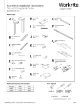
Assembly & Installation Instructions:
Sentinel Pin/Fixed 54"–72" Base
STFH-54-72-XXX-X, ST2P-54-72-XXX-X
Parts Included
B Left Motor Bracket
Qty: 1
C Right Motor Bracket
Qty: 1
D Short Motor Bracket
Qty: 2
G Foot
Qty: 2
A Pin or Fixed Leg
Assembly
Qty: 2
H M6 × 1.0P × 12 mm
Flat Head Allen Screw
Qty: 16
J #12 × ¾" Phillips Pan
Head Screw
Qty: 32
I M8 × 1.25P × 20 mm
Flat Head Allen Screw
Qty: 4
K 4 mm Allen Wrench
Qty: 1
L 5 mm Allen Wrench
Qty: 1
M Glide
Qty: 4
Tools Required:Worksurface Required, Sold Separately:
Cordless Drill #2 Phillips Bit
Screwdriver or
Driver/Drill
⅛" pilot drill bit
pencil
3⁄32" pilot drill bit
#3 Phillips Bit
Screwdriver or
Driver/Drill
E Rear Bracket
Qty: 2
F Connector Bracket
Qty:1
Rectangles Width Depth
24" Feet 52–72" 23–24"
30" Feet 52–72" 29–30"
Offset Corners Width Offset Depth
24" & 30" Feet 58–72" 34–42" 23–24"
30" Feet 58–72" 34–42" 29–30"

2 of 5 Workrite Ergonomics | 800.959.9675 www.workriteergo.com
61"
55"
49"
43"
Assemble rear brackets (E) to connector bracket (F) using
#M6 × 1.0P × 12 mm at head Allen screws (H) and tighten
securely with the 4 mm Allen wrench (K).
Use this guide below to determine the correct holes for
mounting based on the width of your work center.
Note: Workrite brackets can be sized in 3" increments for
any non-Workrite top.
ASSEMBLE REAR STRETCHER BRACKET SET
1.1
1
Hardware at actual size
H M6 × 1.0P × 12 mm Flat Head
Allen Screw
To avoid stripping the threads, always
insert and make the first few turns
of the screw BY HAND with an Allen
wrench (K), ensuring it is in straight.
NOTE!
Only use the #M6 × 1.0P × 12 mm flat
head Allen screw (H) for assembly.
52" Work centers
58" Work centers
64" Work centers
70" Work centers
E
E
E
E
E
E
E
E
H
H
H
H
F
F
F
F

Workrite Ergonomics | 800.959.9675 www.workriteergo.com 3 of 5
Attach one (1) short motor bracket (D) to each leg (A) with
two (2) #M6 × 1.0P × 12 mm at head Allen screws (H) as
shown and tighten securely with the 4 mm Allen wrench (K).
Attach left motor bracket (B) and right motor bracket (C) to sides
of the leg (A) using #M6 × 1.0P × 12 mm at head Allen screws
(H) and tighten securely with the 4 mm Allen wrench (K).
ATTACH BRACKETS TO LEGS
2.1 2.2
Note: The right bracket will be on the left and left bracket on the
right when upside down.
Attach the stretcher bracket set to the rear of the legs (A) with
two (2) #M6 × 1.0P × 12 mm at head Allen screws (H) as shown
and tighten securely with the 4 mm Allen wrench (K).
2.3
2
Le Leg
Right Leg
Stretcher Bracket
A
A
2.1
2.1
2.2
2.2
2.3
2.3
Hardware at actual size
H M6 × 1.0P × 12 mm Flat Head
Allen Screw
H
H
H
H
H
H
D
D
K
B
C

4 of 5 Workrite Ergonomics | 800.959.9675 www.workriteergo.com
6.5
EQUAL SPACING
EQUAL SPACING
Position the base assembly centered left to right and 6.5"
from the back of the worksurface, making sure the legs are
parallel with the back edge of the worksurface.
Using the ⅛" drill bit, drill ¾" deep pilot holes in the four
corner locations.
Note: We recommend you mark your drill bit at ¾" to
prevent drilling too deep.
Caution: Do not drill through the worksurface!
Install four (4) #12 × ¾" Phillips pan head screws (J)
into the 4 corner locations and tighten securely.
Warning: Do not over-tighten and strip the screws
into the top!
Using the ⅛" drill bit, drill ¾" deep pilot holes in the
remaining locations in the brackets on the legs.
Install #12 × ¾" Philips pan head screws (J) into all
pilot holes and tighten securely.
ATTACH BASE ASSEMBLIES TO TOP
3.1 3.2
3.3
3.4
3.5
3
J #12 × ¾" Phillips Pan Head
Screws
Hardware at actual size
3.1
3.5
3.4
3.2
3.3
Front
J
J
J
J
J

5 of 5 Workrite Ergonomics | 800.959.9675 www.workriteergo.com
1500475 Rev B
LEFT LEG RIGHT LEG
Place a foot (G) onto each leg as shown. Install two (2) M8 × 1.25P × 20 mm
at head Allen screws (I) into each foot and tighten securely with the 5 mm
Allen wrench (L).
Install two (2) glides (M) into each foot as shown.
ATTACH FEET
3.1
3.2
Carefully lift and turn table over into use position.
If you have Pin Height legs, adjust from 22" to 34" in 0.5" increments:
Pull pin
Extend legs
Check leg heights to be sure equal length
Insert pin
TURN TABLE OVER
4.1
4.2
4a
4b
4c
4d
4
4.1
3
3.1
3.2
Hardware at actual size
I M8 × 1.25P × 20 mm Flat Head
Allen Screw
G
G
0.5"
0.5"
0.5"
0.5"
I
I
I
M
M
M
M
L
Cleaning Instructions
• To clean the Sentinel legs, apply cleaner to a soft cloth.
• Suggested cleaners: Windex or Formula 409.
• Do not use solvents and do not saturate or spray cleaners directly onto work center base.
Parts & Accessories
Visit http://workriteergo.com/documentation/other/workrite_ergonomics_pricing_specication_guide.pdf
for replacement parts.
✓
✓
4a 4b
4d
4c
/