MICRO-EPSILON thermoMETER CT Assembly Instructions
- Category
- Other input devices
- Type
- Assembly Instructions

Titel
Assembly Instructions
thermoMETER CT
MICRO-EPSILON MESSTECHNIK GmbH & Co. KG
Koenigbacher Str. 15
94496 Ortenburg / Germany
Tel. +49 8542 / 168-0 / Fax +49 8542 / 168-90
e-mail [email protected]
www.micro-epsilon.com
X9771190-A032030HDR
*X9771190-A03*
Warnings
Connect the power supply and the display/output device according to the
safety regulations for electrical equipment.
> Risk of injury, damage to or destruction of the sensor and/or the controller
Avoid shocks and impacts to the sensor and the controller.
> Damage to or destruction of the sensor and/or the controller
Avoid mechanical violence on the sensor.
> Damage to or destruction of the sensor
The supply voltage must not exceed the specified limits.
> Damage to or destruction of the sensor and/or the controller
Protect the sensor cable against damage.
> Destruction of the sensor, failure of the measuring device
Never kink the sensor cable, do not bend the sensor cable in tight radii.
The minimum bending radius is 14 mm (static). A dynamic movement is not
allowed.
> Damage to the sensor cable, failure of the measuring device
Avoid exposure of sensor (both optics and housing) to cleaning agents that
contain solvents.
> Damage to or destruction of the sensor
Avoid abrupt changes of the operating temperature.
> Inaccurate or incorrect measurements
Notes on CE Marking
The following apply to the thermoMETER CT measuring system:
- EU Directive 2014/30/EU
- EU Directive 2011/65/EU, “RoHS” Category 9
The sensor satisfies the requirements if the guidelines in the operating instruc-
tions are maintained in installation and operation.
Proper Environment
- Protection class:
Sensor: IP 65 (NEMA 4)
Controller: IP 65 (NEMA 4)
- Operating temperature:
Sensor: Depending on the sensor model between
-20 °C ... 250 °C (-4 °F ... +482 °F)
1
Controller: 0 ... 85 °C (+32 °F ... +185 °F)
- Storage temperature:
Sensor: Depending on the sensor model between
-40 °C ... 250 °C (-40 °F ... +482 °F)
1
Controller: -40 °C ... 85 °C (-40 °F ... +185 °F)
- Humidity: 10 - 95 %, non-condensing
Unpacking/Included in Delivery
- 1 thermoMETER CT sensor with sensor cable
- 1 Controller
- 1 Connection cable
- 1 Mounting nut
- 1 Assembly instruction
-
1) Specification, also see operating instructions
You can download a PDF of detailed operating instructions from our website:
http://www.micro-epsilon.de/download/manuals/man--thermoMETER-CT--en.pdf
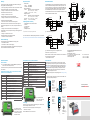
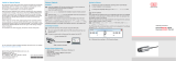
Mechanical Installation
The thermoMETER CT sensors are equipped with a metrical M12x1-thread
and can be installed either directly via the sensor thread or by means of the
hex nut (included in scope of supply) to the mounting bracket available. Var-
ious mounting brackets which make the adjustment of the sensor easier can
be ordered additionally as accessories, also see operating instructions.
The thermoMETER CTH and CTP sensors are delivered with massive housing
and can be installed via the M18x1-thread.
10
(.39)
M12x1
max. 3 (.12)
2.8 (.11)
28 (1.1)
WS 14
Ø14
(.55 dia.)
Ø10 (.39 dia.)
Fig. 1 Dimensional drawing of sensor
32
(1.26)
M12x1
max. 3 (.12)
Ø14
(.55 dia.)
Ø10
(.39 dia.)
Ø2.8
(.11 dia.)
WS 14
10
(.39)
Fig. 2 Dimensional drawing of sensor with integrated CF lens
Dimensions in mm (inches), not to scale
With the CT-SF02 / CTH-SF02 / CTH-SF10 models, the sensor cable must not
be moved during the measurement.
> False measurement results
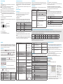
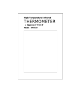
Electrical Installation
Cable Connections
For the electrical installation of the thermoMETER CT, please open at
first the cover of the controller (4 screws).
For the cable connection, you will find the screw terminals in the lower section
of the controller.
Pin Assignment for CT-SF02, CT-SF15, CT-SF22, CTF-SF25, CTH-SF02,
CTH-SF10, CTP-7 and CTP-3 Models
Pin Designation
+8 ... 36 VDC Power supply
GND Ground (0 V) of power supply
GND Ground (0 V) of internal in- and outputs
OUT-AMB Analog output sensor temperature (mV)
OUT-TC Analog output thermocouple (J or K)
OUT-mV/mA Analog output object temperature (mV or mA)
F1-F3 Functional inputs
AL2 Alarm 2 (Open-collector output)
3V SW 3 VDC, switchable for laser sighting tool
GND Ground (0 V), for laser sighting tool
BROWN Temperature probe (sensor)
WHITE Temperature probe (sensor)
GREEN Detector signal (-)
YELLOW Detector signal (+)
Fig. 5 Opened controller
CT-SF02, CT-SF15, CT-SF22,
CTP-7, CTF-SF15, CTF-SF25,
CTH-SF02, CTH-SF10 with
terminal connections
Pin Assignment for CTM-1, CTM-2, CTM-3 Models
Pin Designation
+8 ... 36 VDC Power supply
GND Ground (0 V) of power supply
GND Ground (0 V) of internal in- and outputs
AL2 Alarm 2 (Open collector output)
OUT-TC Analog output thermocouple (J or K)
OUT-mV/mA Analog output object temperature (mV or mA)
F1-F3 Functional inputs
GND Ground (0 V)
3V SW 3 VDC, switchable for laser sighting tool
GND Ground (0 V), for laser sighting tool
BROWN Temperature probe sensor (NTC)
WHITE Sensor ground
GREEN Power supply (sensor)
YELLOW Detector signal
Fig. 6 Opened controller
CTM-1, CTM-2, CTM-3 with
terminal connections
Power Supply
Please use a power supply unit with an output voltage of 8 - 36 VDC/100 mA.
The residual ripple should be max. 200 mV.
Please do never connect a supply voltage to the analog outputs.
> Destruction of the output
The thermoMETER CT is not a 2-wire sensor!
Ground Connection
At the bottom side of the main board PCB, you will find a plug connector
(jumper). Depending on the position, the ground connections (GND power
supply/ output) are connected with the ground of the controller housing, see
Fig. 7, see Fig. 9. To avoid ground loops and related signal interferences, in
industrial environments it might be necessary to interrupt this connection.
Remove the board in order to switch the jumper on the back of the
board by loosening the two screws.
Please put the jumper in the corresponding position, see Fig. 8, see Fig.
10.
i
If the thermocouple output is used, the ground connection GND - hous-
ing should generally be interrupted.
Fig. 7 Plug
connector
(jumper),
GND to
housing;
CT-SF, CT-CF,
CTF, CTH,
CTP models
Fig. 8 Plug
connector
(jumper),
GND - open;
CT-SF, CT-CF,
CTF, CTH, CTP
models
Fig. 9 Plug
connector
(jumper),
GND to
housing;
CTM models
Fig. 10 Plug
connector
(jumper),
GND - open;
CTM models
Position for
screw fixing of
board
WS 24
45 (1.77)
40 (1.57)
39 (1.54)
10
(.39)
M18x1
4
(.16)
ø23
(.91 dia.)
Fig. 3 Dimensional drawing of massive housing, CTH and CTP models
47 (1.85)
70 (2.76)
23 (.9)
24
(.94)
89 (3.5)
max. 120 (4.72)
92 (3.6)
110 (4.33)
22 (.87)
30 (1.18)
13 (.51)
4 (.16)
ø4.5
(.18 dia.)
M12x1.5
4 (.16)
4
23
(.91)
4
(.16)
ø4.5
(.18 dia.)
Fig. 4 Dimensional drawing of controller
Dimensions in mm (inches), not to scale

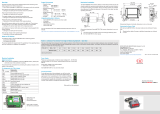
Cable Assembling
Mounting
The cable gland M12x1.5 of the controller allows the use of cables with an
outer diameter of 3 to 5 mm.
Remove the insulation from the cable (40 mm power supply,
50 mm signal outputs, 60 mm functional inputs).
Cut the shield down to approx. 5 mm and spread the strands out.
Extract about 4 mm of the wire insulation and tin the wire ends.
Place the pressing screw, the rubber washer and the metal washers of
the cable gland one after the other onto the prepared cable end.
Spread the strands and fix the cable shield between two of the metal
washers.
Insert the cable into the cable gland until the limit stop.
Screw the cap tightly.
Every single wire may be connected to the appropriate screw clamps accord-
ing to their colors.
Pressing screw
Shield
Metal washer
Rubber washer
Fig. 11 Cable installation
i
Use shielded cables only!
The sensor shield has to be grounded!
Shortening the Sensor Cable
With all CT models (except for CTM-3, CTP-7), the sensor cable can be short-
ened if necessary. With the models CTM-1, CTM-2 and CTF, the sensor cable
can be shortened by max. 3 m. The CTM-3 models are only available with
3 m cable.
i
Shortening the cable will cause an additional measuring error of about
0.1 K/ m.
Inputs and Outputs
Analog Outputs
The thermoMETER CT has either one or two analog output channels.
Please do never connect a supply voltage to the analog outputs.
The thermoMETER CT is not a 2-wire sensor!
> Destruction of the output
Output Channel 1
This output is used for output of the object temperature. Selection of the
output signal is carried out via programming keys. The CompactConnect
software enables to program the output channel 1 also as an alarm output.
Output signal Range Connection pin on CT board
Voltage 0 ... 5 V OUT-mV/mA
Voltage 0 ... 10 V OUT-mV/mA
Current 0 ... 20 mA OUT-mV/mA
Current 4 ... 20 mA OUT-mV/mA
Thermocouple TC J OUT-TC
Thermocouple TC K OUT-TC
i
Please note that according to the chosen output, different connection
pins are used (OUT-mV/mA or OUT-TC).
Output Channel 2 (only CT-SF02, CT-SF15, CT-SF22, CTH, CTP-7 and
CTP-3)
The connection pin OUT-AMB is used for output of the sensor temperature.
The CompactConnect software allows the programming of output channel 2
as an alarm output. Further details, see operating instructions.
Digital Interfaces
Please refer to the operating instructions for the description of the optional,
digital interfaces. The following interfaces are available: USB, RS232, RS485,
Profibus DP, CAN-Bus, Modbus RTU or Ethernet.
Functional Inputs
The three functional inputs F1 - F3 can be programmed with the Compact-
Connect software, only.
Functional inputs Description
F1 (digital) Trigger (a 0 V - level on F1 resets the hold
functions)
F2 (analog)
External emissivity adjustment [0 - 10 V: 0 V
e = 0.1; 9 V e = 1; 10 V e = 1.1]
F3 (analog) External compensation of ambient tempera-
ture/the range is scalable via CompactConnect
software.
[0 - 10 V: -40 - 900 °C/preset range: -20
-200 °C]
F1 - F3 (digital) Emissivity (digital choice via table)
A non-connected input represents:
F1 = High
F2, F3 = Low
High-level: ≥ +3 V ... +36 V
Low-level: ≤ +0.4 V ... -36 V
Alarms
The thermoMETER CT has following alarm features:
All alarms (alarm 1, alarm 2, output channel 1 and 2 if used as alarm output)
have a fixed hysteresis of 2 K CTH: 1 K).
Output Channel 1 and 2 (Channel 2 on CT-SF / CTP-7 and CTP-3)
The respective output channel has to be switched into digital mode for activa-
tion. For this the CompactConnect software is required.
Visual Alarms
These alarms will cause a change of color of the LCD display and will also
change the status of the optional relays interface. In addition, Alarm 2 can be
used as open collector output at pin AL2 on the controller [24 V/ 50 mA].
The alarms are factory-set as follows:
Alarm 1 Norm. closed/Low-Alarm
Alarm 2 Norm. open/High-Alarm
Both of these alarms will have effect on color setting of the LCD display:
BLUE Alarm 1 active
RED Alarm 2 active
GREEN No alarm active
For extended setup like definition as low or high alarm (via change of normally
open/closed), selection of the signal source [TObj, THead, TBox] a digital in-
terface (e.g. USB, RS232) including the CompactConnect software is needed.
CompactConnect Software
Insert the CompactConnect installation CD into the appropriate drive
of your PC or download the software from our website at:
https://www.
micro-epsilon.de/download/software/thermoMETER-CompactConnect/.
If the auto run option is activated, the installation wizard will start automatical-
ly. Otherwise, please start CDsetup.exe from the CD-ROM.
Please follow the instructions of the wizard until the installation is fin-
ished.
After installation, you will find the CompactConnect software on your desktop
(as a program icon) and in the start menu.
If you want to uninstall the CompactConnect software from your system,
please use the Uninstall icon in the start menu.
You will find detailed software manual on the CompactConnect CD.
System Requirements
- Windows 7, 8 and 10
- At least 128 MByte RAM
- USB Interface
- CD-ROM drive
- Hard disc with at least 30 MByte free space
Main Features
- Graphic display and
recording of temperature
readings for subsequent
analysis and documenta-
tion
- Complete set up of param-
eters and remote control of
the sensor
- Sophisticated signal pro-
cessing features
- Output scaling and param-
eter set up of functional
inputs
i
A detailed description of the commands you will find on the Compact-
Connect software CD in the directory: \Commands.
Operation
After powering up the supply voltage, the sensor starts an initializing routine
for some seconds. During this time the display will show INIT. After this pro-
cedure, the object temperature is shown in the display. The display backlight
color changes according to the alarm settings.
Sensor Setup
The programming keys , and enable the user to set the sensor
on-site. The current measuring value or the chosen feature is displayed. The
current measuring value or the chosen feature is displayed. With the op-
erator obtains the chosen feature, with and the functional parameters
can be selected – a change of parameters will have immediate effect. If no
key is pressed for more than 10 seconds the display automatically shows the
calculated object temperature (according to the signal processing).
Mode
Up
Down
Pressing the button again recalls the last
called function on the display.
The signal processing features peak hold and
valley hold cannot be selected simultaneously.
Fig. 12 Display and programming keys
Restoring Factory Setting
To reset the thermoMETER CT to the factory settings, please first press
the and then the button and keep both pressed for 3 seconds.
The display will show RESET for confirmation.
Display Mode (Example) Adjustment range
142.3C Object temperature
(after signal processing) [142.3 °C]
Fixed
127CH Sensor temperature [127 °C] Fixed
25CB Box temperature Fixed
142CA Current object temperature Fixed
Display Mode (Example) Adjustment range
MV5
Signal output channel 1 [0 - 5 V]
0 - 20 = 0 - 20 mA/
4 - 20 = 4 - 20 mA/
MV5 = 0 - 5 V/
MV10 = 0 - 10 V/
TCJ = Thermocouple
type J/
TCK = Thermocouple
type K
E0.970 Emissivity [0.970] 0.100 ... 1.100
T1,000 Transmission [1.000] 0.100 ... 1.100
A 0.2 Signal output average [0.2 s] A---- = inactive/
0.1 ... 999.9
P---- Signal output peak hold [inactive] P---- = inactive/0.1 ...
999.9 s/P ∞ ∞ ∞ ∞ =
infinite
V---- Signal output peak hold [inactive] V---- = inactive/ 0.1 …
999.9 s/ V oo oo oo oo =
infinite
u 0.0 Lower limit temperature range [0 °C] Depending on model/
inactive at TCJ and TCK
output
n 500.0 Lower limit temperature range [500 °C]
[ 0.00 Lower limit output signal [0 V] According to the range of
the selected output
] 5.00 Upper limit output signal [5 V]
U °C Temperature unit [°C] °C/ °F
/ 30.0 Lower alarm limit [30 °C] Depending on model
// 100.0 Upper alarm limit [100 °C] Depending on model
XHEAD Ambient temperature compensation
[Sensor temperature]
XHEAD = sensor tem-
perature/-40.0 ... 900.0 °C
(for LT) as fixed value for
compensation/ returning
to XHEAD (sensor tem-
perature) by pressing
and
together
Display Mode (Example) Adjustment range
M 01 Multi-drop address [1]
(only with RS485 interface)
01 ... 32
B 9.6 Baud rate in kBaud [9.6] 9.6/19.2/38.4/57.6/115.2
kBaud
S ON Laser sighting (3 VDC-switches to the
connection pin „3 VSW“)
ON/OFF; This menu item
appears on the models
CTM-1, CTM-2, CTM-3 on
first position.
Error Messages
The display of the thermoMETER CT can show the following error messages:
CT-SF02, CT-SF15, CH-SF22, CTH and CTP-7 Models
OVER Object temperature too high
UNDER Object temperature too low
^^^CH Sensor temperature too high
vvvCH Sensor temperature too low
CTM-1, CTM-2, CTM-3 Models
1. Digit
0x No error
1x Sensor temperature probe short circuit GND (bn)
2x Box temperature too low
4x Box temperature too high
6x Box temperature probe interrupted
8x Box temperature probe short circuit to GND
2. Digit
x0 No errors
x2 Object temperature too high
x4 Sensor temperature too low
x8 Sensor temperature too high
xC Sensor temperature probe interrupted (bn)
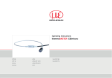
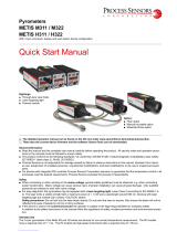
Ratio D = Distance from the front edge of the device to the measuring object / S = Spot Size
The size of the object to be measured and the optical resolution of the infrared thermometer determine the maximum distance between sensor and object. In
order to prevent measuring errors, the object should fill out the field of view of the sensor lens completely. Consequently, the spot should at all times have at
least the same size as the object or should be smaller than that.
Models
S D S D S D S D S D S D S D S D S D S D S D
CT-SF15
CTF-SF15
6.5 0 11.6 100 16.6 200 21.7 300 26.7 400 35 500 43.3 600 51.6 700 59.9 800 68.2 900 76.5 1000
Fig. 13 Example
Please refer to the operating instructions for further D/S ratios.
-
 1
1
-
 2
2


MICRO-EPSILON thermoMETER CT Assembly Instructions
- Category
- Other input devices
- Type
- Assembly Instructions
Ask a question and I''ll find the answer in the document
Finding information in a document is now easier with AI
Related papers
-
MICRO-EPSILON thermoMETER CS Assembly Instructions
-
-
 MICRO-EPSILON thermoMETER CT Owner's manual
-
 MICRO-EPSILON thermoMETER CTM-4 Assembly Instructions
-
 MICRO-EPSILON M-3H Owner's manual
-
 MICRO-EPSILON thermoMETER CTL Assembly Instructions
-
-
 MICRO-EPSILON thermoMETER CTL Owner's manual
-
 MICRO-EPSILON thermoMETER TIM 8 / thermoIMAGER TIM 40 Assembly Instructions
-
 MICRO-EPSILON thermoMETER CX Owner's manual


Other documents
-
Parallax SF02-AS Arduino Shield User guide
-
 Lutron Electronics TM-939 User manual
-
Shure MV5 User guide
-
-
Chromalox CTF Hardware Instruction Manual
-
kincrome K8006 User manual
-
AMX CTP-1301 Quick start guide
-
 Process Sensors METIS M311 Quick start guide
-
EDWARDS CTM City Tie Module Installation guide
-

