Process Sensors METIS M311 Quick start guide
- Category
- Measuring & layout tools
- Type
- Quick start guide

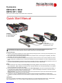
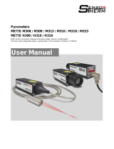
Pyrometers
METIS M311 / M322
METIS H311 / H322
With12-pinconnector,displayandpushbuttondeviceconguration
Optics:
■Fiberoptics
■Manualfocusableoptics
■Motorizedfocusoptics
Sightings:
■Through-lensviewnder
■Laser targeting light
■Camera module
The detailed operation manual can be found on the CD and under www.sensortherm.de/en/download-section.
There also the current device rmware and the software SensorTools can be downloaded.
General Information
■Readthismanualandthecompleteusermanualcarefullybeforeoperatingtheproduct.Allsecuritynotesandoperationproce-
duresinthemanualsmustbefollowedtoensuresafety.
■Theproductconformstothefollowingstandards:CEconformity:DINEN61326-1(electromagneticcompatibility),lasersafety:
IEC60825-1(laserclass2),RoHS:2011/65/EU.
■ProcessSensorsisnotresponsiblefordamagecausedbyfailuretoobserveinstructionsinthismanual,deviationfromintend-
eduse,assignmentofunskilledpersonnel,unauthorizedmodications,technicalmodicationsortheuseofunapprovedspare
parts.
■FordeviceswithintegratedPIDcontrollerProcessSensorsCorporationassumesnoguaranteethatthetemperaturecontrolinall
processesmeetthedesiredrequirements.ProcessSensorsexcludestheprocessofresponsibility.
Safety
■When connecting or when working on the mains voltage,generalsafetyguidelinesmustbeobserved,e.g.whenconnecting
powertransformers.Mainsvoltagecancauseseriousinjury.Improperinstallationcancausephysicaldamage.Onlyqualied
personnel are allowed to work with mains voltage.
■Foreasyalignment,thepyrometersmaybeequippedwithalaser targeting light, Laser Class 2 (according to IEC 60825-1-3-
4).Thelaseremitsavisibleredlightwithamaximumpowerof<1mWandawavelengtharound650nm.Deviceswithlaser
targeting light are marked with a yellow “CAUTION” sticker.
Safety precautions: Do not look into the laser beam directly. Do not point the laser to anyone. Also ensure the beam will not be
reectedintoeyesofpeoplebymirrorsorshinysurfaces.
■Ifthedeviceisusedinthecommercial sector theoperatorissubjecttothelegalresponsibilitiesforworkplacesafety.
Inadditiontothesafetyinstructionsinthismanualfollowtheregulationsofsafety,accidentpreventionandenvironmentalprotec-
tion.
Intended Use
The2-colorpyrometersoftheMetisM3andH3seriesaredevicesfornon-contacttemperaturemeasurement.TheM3models
havearesponsetimeof<1ms.TheH3modelsarehigh-speedinstrumentswitharesponsetimeof<80µm.
QuickStartManual

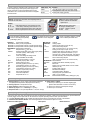
1 Electrical Connection
2 Overview
Theunitisreadyforoperationwhenconnectionismade
to the voltage supply. Interrupt the power supply to turn
othepyrometer.Topreventaccidentalshortcircuits,
cable wires not in use should be secured to the supplied
screw terminals.
Cable color No. Function
White 1 + 24 V DC power supply (18–30 V DC, power
consumptionM3:max.6VA,H3:max.12VA)
Brown 2 0 V DC power supply (ground)
LEDs 1,2,3 (Active digital outputs)
■Green: Indicates an activated
digital output
Sighting:Through-lensviewnder,lasertargetingbuttonor
connectorforcolorvideo
LED 4 (Operating status LED)
■Orange:Self-testphase
■Green: Ready to operate
■Red: Error
Display
■2C: Ratio temperature (2-color) measuring mode
■C1 / C2: 1-color temp. measuring mode channel 1 or 2
■– – – –: Measuring temperature below zero scale temp.
■OVER: Measuringtemperatureabovefullscaletemp.
DISPLAY> Temperature on display
DISPTMP:2C Ratio (2-color) temperature
DISPTMP: C1 Temperature channel 1 (longer spectral range)
DISPTMP: C2 Temperature channel 2 (shorter spectral range)
MEASPARA> Measurement parameters
T90 Response time t90 (min–10 s)
STMOD Storagemodepeakpicker:OFF,trigger(TRIG),
automatic (AUTO), extern (EXT),
time clear (TIME)
CLR Cleartimesettingsofstoragemode
(onlyifSTMODEsettoTIME):
timesfortimeclearing:1ms–25s
SLO Emissivity slope (0.800–1.200)
SW.OFF Switch-olimit(2–90%)
Ԑ1 Emissivity(epsilon)channel1(5–120%)
TR1 Transmittancechannel1(5–100%)
Ԑ2 Emissivity(epsilon)channel2(5–120%)
TR2 Transmittancechannel2(5–100%)
FF Fillfactorofspotsize(5–100%)
ZSC Zero scale temperature
FSC Fullscaletemperature
TU Temperateunit°C/°F
OUTPUTS> Outputs
ANALOG> Analog outputs
A1 Analog current output 1 (0/4–20 mA)
A1TST Test current analog output 1
(OFF,10mAat0–20mA,12mAat4–20mA)
A2 Analog current output 2 (0/4–20 mA)
A2OUT Signalanalogoutput2:o(OFF),2-colortem-
perature (2C), temperature channel 1 (C1) or
channel 2 (C2), control output (CTR; only devices
with PID controller), device temperature (DTMP)
A2TST Test current analog output 2
(OFF,10mAat0–20mA,12mAat4–20mA)
INTERFACE> Serialinterface
RSTYPE InterfacetypeRS232/RS485(onlyM3)
BD Baud rate
RS232: 4.8–115.2 kBd, RS485: 4.8–921.6 kBd
ADD Address (00–97)
DELAY Interfacedelay(00–20)
MISC> Miscellaneous settings
LG Language (English / Deutsch)
N.PIN Set(new)pinforpushbuttonlock
(OFF=nopinrequest)
FACT.SET Resetthedevicetothefactorysetting(no/yes)
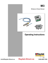
5 Adjusting the Measuring Distance / Focus Distance
Inthefocuspointofthelens(focusdistance)thespotsizediameterissmallest,outsidethefocuseddistancethespotsizediameter
isusuallybigger.Precisespotsizescanbefoundinthecompleteoperatingmanualunder“SpotSizeTables”.
■The laser targeting light has its smallest and sharpest picture at the point where the spot size is the smallest.
■ View nder and Camera Module:Themeasuringdistanceisfoundwhentheobjectisinfocus.
4 Factory Settings
■Analog output 1:4–20mA,signalofthemeasuredtempera-
ture (always that temperature, displayed on the device)
■Analog output 2: no temperature output
■Serial interface: RS485, baud rate: 115.2 kBd
■Emissivity slopeԐ2/Ԑ1=1,emissivity Ԑ=1(100%)
■Response time t90=min(correspondsM3:<1ms;H3:<80µs)
■Digital inputs / outputs
- 1:Settoinput:switchingon/olasertargetinglight
(deviceswithviewnderorcamera:nofunction)
- 2:Settoinput:clearingofpeakpickerstorage
- 3:Settoinput:nofunction
Press the button repeatedly to get
access to all settings sequentially
(subcategory with >)
Foradjustmentofthepossible
parameters in the categories
Opens a parameter category or takes
overamodiedparametervalue
4 Parameters(adjustmentbuttonsforpyrometerconguration)
Manual Focusable Optics Fiber Optics Motorized Focus
1. Release
2. Adjust
3. Lock (hand-
screwed)
1.
1.
2.
2.
3. 3.
1.
2.
3.
Hexagonsocket1.5mm
Astickerontheopticsshowsthemeasurement/focusdistance(“a”fromfrontofthelens)

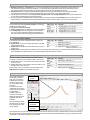
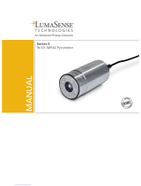
10 SensorTools Software (min. Windows 7)
All pyrometer settings can
beadjustedviasoftware
when a PC connection is
established via the serial
interfaceport(forexam-
ple,viaanUSBinterface
converter).
Functionssuchasthe
congurationoftheinputs/
outputs can only be carried
outviasoftware.
In addition, the mea-
surement value trend is
displayed numerically and
graphically and can be
recorded.
With connected pyrometer
the device keys are locked,
when pressing a key “KEY
LOCK” appears.
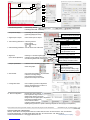
7 Connecting Analog Devices
The pyrometer has 2 separate analog outputsforconnecting
additional evaluation devices:
■Adjustable to 0-20 mA or 4-20 mA
■Analog output 1 always provides the measured temperature
■To analog output 2 can be assigned the 2-color tempera-
ture, the 1-channel temperature, the device temperature or
thecontrolvaluefordevicesequippedwithaPIDcontroller
Cable color No. Function
Green 3 + Analog output 1 (0 / 4–20 mA)
Yellow 4 - Analog output 1 (0 / 4–20 mA)
White-green 14 + Analog output 2 (0 / 4–20 mA)
Brown-green 15 - Analog output 2 (0 / 4–20 mA)
8 Congure Inputs / Outputs
3viasoftwareSensorTools congurableinputs/outputsare
each available as:
■Digital output:outputofaswitchingsignal(50mA)atdier-
ent temperature events.
■Digital input:switchdevicefunctionsexternallyviaaninput
voltage pulse.
■Analog input (only M3): adjust via external 0–20 mA the emissivity slope, emissivity (at 1-channel measurements), the setpoint
(whenequippedwithaPIDcontroller)orthemeasuringdistance(atmotorizedfocusoptics).
Cable color No. Function
Grey 5 Digital input / output 1 1)
Pink 6 Digital input / output 2 1)
Blue 13 Digital input / output 3 / Analog input 1)
1)Referencepotential0V,brown
9 UseoftheSerial Interface
Theserialinterfaceisusedfordigitalcommunicationwitha
computer,forexampleviatheincludedsoftwareSensorTools.
■RS232:Baudrate4.8–115.2kBdforashortdirectconnection
up to max. 20 m.
■RS485:Baudrate4.8–921.6kBdfordirectconnectionorbus
operation with up to 32 devices.
The pyrometer can be connected to a PC with USB port via a
USB interface converter (recommended accessory).
Cable color No. Function
Black 9 RS232: RxD; RS485: B (+) 2)
Grey-pink 11
Violet 10 RS232: TxD; RS485: A (-) 2)
Red-blue 12
Red 8 DGND(groundforinterface)
2)H3modelsonlyRS485
6 Important Measuring Parameters
■ Emissivity slope Ԑ2/Ԑ1 or emissivity Ԑ:Foracorrectmeasurementresult,thesurfacecharacteristicsandtheemissivityof
the material to be measured must be considered. In 2-color temperature measurement mode this is the emissivity slope, in
one-channelmodethisistheemissivity(anemissivitytablecanbefoundintheoperatinginstructions).
■Response time t90:Shortsettingenablethefastestmeasurement.Atlongerresponsetimes,themeasurementsignalis
smoothedandaveragevaluesfortemperatureuctuationsareformedcausedbytheinertialmeasurement.
■The storage mode is turned on when the peak value, minimum value or the average temperatureofthecurrentmeasurement
is to be captured and displayed or used via the outputs.
■Ifaviewingwindowislocatedbetweenthemeasuringobjectandthepyrometer,thetransmittanceofthewindowmustbecon-
sideredduringthemeasurement.Enterthetransmittanceofthewindowinordertoobtainacorrectmeasurementresult.
About SensorTools,thepyrometercanbeupdatedtoanewrmwareversiontoxbugsoraddnewfeatures.SensorTools including
thelatestrmwarecanbedownloadedfromthewebsiteatwww.sensortherm.de/en/download-section(givenbyenteringthemodel
number(rst4characters)andserialnumberrequired).
3. Congure
5. Record /
Analyze
2. Set measurement
parameters
1. Connect the
pyrometer

1. Connect the pyrometer: - automatically (search)
- manually (select COM à connect)
2. Temperature display: - numerically (as on the pyrometer)
- graphically (displayed in time)
3. Digital inputs / outputs: - shows active inputs or outputs
4. Set measuring parameters: - measuring relevant
- rarely required
( and to extend)
5. Savemeasuringparameters:-saveallvaluesunderalename
6.Alignment: -switchingon/olasertargetinglight
(Iconsdevice-dependent) -conguremonitorsettingsofthecameramodule
-setmeasuringdistanceatmotorizedfocus
7. Graphic presentation: - customize view in the data recording window
- select view graphs
8. Record data: - save measurement data incl. all parameters
- customize recording settings
-showmeasurementinformation
- playback and analyze in the viewer
9. CongurationFiles: -savecompletepyrometercongurations
(setups) and activate them on the PC or
externally via digital inputs
10. Deviceconguration: -performbasicdevicesettings
-limittemperaturerangeifnecessary
- adapt analog outputs to terminals
-assignfunctionstodigitalinputs/outputs
- test analog and digital outputs
-accessservicefunctions
-congureinterfaceanddatacollectionsettings
-adjustingthepyrometertoaspecicmeasuringtemperaturevalue(single-pointadjustment)
Measuring temperature
DT: read out device temperature
IN: digital inputs , OUT: digital outputs
Port not activated, inactive, active
Select measurement parameters
or type in or via
quickadjustment(activeeld)
Measuring mode selection
Savepyrometerparametersinle
Loadparametersfromle
Parametersarereadfrompyrometer
Parametersofcurrentlyloadedle
Laser targeting light
Measuringdistanceatmotorizedfocus
Monitorsettingsofcameramodule
Scale per mouse click
Scale per entry
Scale with mouse drag
Adapt to pyrometer’s temp. range
Automatic scale (selected graphs)
2
3
4
5
6
1
10
ProcessSensorsreservestherighttomakechangesinscopeoftechnicalprogressorfurtherdevelopments. Quickstart-Manual_M3_H3_RatioPyrometers_12-pin
(Feb14,2017)
9
7
8
PROCESS SENSORS CORPORATION
IRTemp.SalesOce:787SusquehannaAvenue,FranklinLakes,NJUSA•Tel:201-485-8773•Fax:201-485-8770
CorporateHeadquarters:113CedarStreet,Milford,MAUSA•Tel:508-473-9901•Fax:508-473-0715
www.ProcessSensorsIR.com•[email protected] A KPM Analytics Company
-
 1
1
-
 2
2
-
 3
3
-
 4
4


Process Sensors METIS M311 Quick start guide
- Category
- Measuring & layout tools
- Type
- Quick start guide
Ask a question and I''ll find the answer in the document
Finding information in a document is now easier with AI
Other documents
-
 SensorTherm METIS M318 User manual
-
 LumaSense IGA 12 User manual
-
 MICRO-EPSILON CTRatio Owner's manual
-
Omega OSAO-Series Owner's manual
-
 RayTek MI3 Operating Instructions Manual
-
 LumaSense IN 5/5 User manual
-
 AST AL390 Operating instructions
-
-
 LumaSense IGA 320 User manual
-
 Palmer Wahl DHS40 User manual


