Page is loading ...

i
PK533-1
0037-75557
April 2016
Hardware Instruction Manual
CTF Advanced SCR
Power Controller
CTF
25A to 120A
CTF
150A to 250A

ii
Important Safeguards ............................................................................................................. 1
1. Initial Instructions .............................................................................................................. 2
1.1 General Description ................................................................................................................................. 2
1.2 Features ................................................................................................................................................... 2
1.3 Product Inspection ..................................................................................................................................2
2. Dimensions & Weights ...................................................................................................... 3
3. Installation - Mounting ...................................................................................................... 3
4. Installation - Wiring ........................................................................................................... 4
5. Emission, Immunity and Safety Standards ..................................................................... 6
6. Controller Overview .......................................................................................................... 7
6.1 Layout ................................................................................................................................................... 7
6.2 Cooling Fan ............................................................................................................................................. 8
6.3 Replacing Internal Fuse ........................................................................................................................... 9
7. Connections and Indication ........................................................................................... 10
7.1 I/O Connections – CTF 25A - 125A ....................................................................................................... 10
7.2 I/O Connections – CTF 150A - 250A ..................................................................................................... 11
7.3 LED Logic .............................................................................................................................................. 12
7.4 Control Connections ..............................................................................................................................12
7.4.1 J1 Control (CTF 25A - 120A) ...................................................................................................12
7.4.2 J1 Output (CTF 150A - 250A) .................................................................................................. 13
7.4.3 J2 24V Power Supply (CTF 150A - 250A)................................................................................13
7.4.4 J3 Digital Input (CTF 150A - 250A) .......................................................................................... 14
7.4.5 J4 Analog Input (CTF 150A - 250A) ......................................................................................... 14
7.5 Recommended Wire Gages ..................................................................................................................15
7.6 TTL Configuration Port .......................................................................................................................... 16
7.7 Modbus RS485 Ports (Option) .............................................................................................................. 16
8. Load Connection Examples ........................................................................................... 17
9. Inductive and Transformer Coupled Load Guidelines ................................................. 24
10. Firing (Trigger) Mode Overview ...................................................................................... 24
10.1 Additional Control Functions ................................................................................................................. 26
10.2 Digital Input or PWM (Pulse Width Modulation) .................................................................................... 28
11. Communications Port (Modbus RTU/RS485) ............................................................... 29
11.1 Controller Configuration ........................................................................................................................29
12. Autobaud Function .......................................................................................................... 30
13. Specifications .................................................................................................................. 31
13.1 Derating Curves ..................................................................................................................................... 34
14. Ordering Information ....................................................................................................... 35
15. Configuration and Programming ................................................................................... 36
15.1 C-PWR Configuration Software Program .............................................................................................. 36
15.2 CTF/CTF-Xtra Programming Manual .....................................................................................................36
16. Fuses and Fuse Holders ................................................................................................. 36
Table of Contents

1
HIGH VOLTAGE (up to 690 VAC) is used in the
operation of this equipment; DEATH ON CON-
TACT may result if personnel fail to observe
safety precautions.
Learn the areas containing high-voltage con-
nections when installing or operating this
equipment.
Be careful not to contact high-voltage connec-
tions when installing or operating this equip-
ment.
Before working inside the equipment, turn
power off and ground all points of high poten-
tial before touching them.
The owner/installer must provide all necessary
safety and protection devices and follow all
current electrical wiring standards and regu-
lations. Failure to do so may compromise the
integrity of the controller and/or cause product
failure resulting in a safety risk to operational
and service personnel.
This controller utilizes a heat sink which is de-
signed to cool the unit during operation. Un-
der no circumstance should air flow around the
controller be compromised in any way. Failure
to do so may result in the overheating of the
controller, product failure, product tempera-
tures and even fire.
During continuous operation, the heat sink can
reach very high temperatures, and keeps a
high temperature even after the unit is turned
off due to its high thermal inertia.
Higher voltages may be present. DO NOT work
on the power section without first cutting out
electrical power to the panel. Failure to do so
may cause serious injury or death.
ELECTRIC SHOCK HAZARD: Any installation in-
volving control equipment must be performed
by a qualified person and must be effective-
ly grounded in accordance with the National
Electrical Code to eliminate shock hazard.
Important Safeguards

2
1. Initial Instructions
1.1 General Description
CTF is a compact advanced SCR power controller that
provides a unique combination of performance, reli-
ability, and flexibility. The CTF controllers are based on
an extremely versatile hardware and software platform,
with options to select the best I/O configuration for
your system.
The CTF may be used as the power controller of single
phase loads or as the Master Controller for 2- or 3-Leg,
3-phase loads. With the multiple command signal op-
tions, the CTF is designed to manage several types of
loads including resistive loads with high and low tem-
perature coefficient, short wave IR lamps, or trans-
former primaries.
In particular, this new line of Chromalox controllers is
the ideal solution for applications demanding high per-
formance, continuous process monitoring and voltage,
current, and temperature diagnostics such as:
• General industrial process heating
• Thermoforming
• Hot runners & injection molding
• Heat treatment furnaces
• Glass tempering furnaces
1.2 Features
• Rugged, industrial design & touch-safe exterior
• Ratings from 25 A to 250 A, at nominal voltages of
480 VAC, 600 VAC, and 690 VAC
• Configurable analog and digital command inputs
• Several trigger modes, including; zero crossing
(fixed cycle, burst-firing (D.O.T.), half single-cycle)
and phase angle
• Current, voltage and temperature diagnostics
• Total and partial load interrupt
• Self-learn function of alarm limit for interrupted load
• SCR in short circuit
• Load in short circuit or overcurrent
• Master or slave Modbus RTU/RS485
• Integrated heat sink (and fan where applicable)
• cULus and cCSAus Listed, TÜV certified, CE
1.3 Product Inspection
Immediately after unpacking the unit and prior to in-
stalling, check the order code and the other data on
the label attached to the outside of the container and
write them down. If troubleshooting is necessary, you
will need to provide this data to a Chromalox customer
service representative.
Upon removing package, ensure that there is no physi-
cal damage to the controller during shipment, and that
the package also contains the “Configuration and Pro-
gramming” manual.
If there are signs of damage or if any parts are missing,
notify your Chromalox representative immediately.
See “Mounting Dimensions” and “Mounting Template”
figures in this document before installing the CTF on
the machine/host system control panel.

3
To ensure proper performance, maximum safety and
reliability, it is essential to install the unit correctly. This
includes proper mounting, spacing, hardware and wir-
ing. See below:
• Maximum surrounding air temperature is 40°C in
“Open Type Equipment” which is suitable for use in
pollution degree 2. For temperature >40°C refer to
the Derating Curves.
• Install the unit vertically (max 10° inclination from
vertical axis).
Spacing
To ensure maximum reliability, the device must be cor-
rectly installed in the panel in such a way as to obtain
adequate heat exchange between the heat sink and the
surrounding air under conditions of natural convection.
Under no circumstance shall any component, including
cable channels, compromise minimum thermal spac-
ing dimensions. Air must be able to flow vertically on
the heat sink without any obstacles.
Considerations:
Solid state devices dissipate heat which may impact
installation room temperature.
Exchange with external air or an air conditioner may be
necessary to transfer heat outside the panel.
• Minimum vertical distance between unit and panel
wall: 3.9” (100 mm)
• Minimum horizontal distance between unit and pan-
el wall: 25 A to 120 A: 0.8” (20 mm), 150 A to 250 A:
0.4” (10 mm)
• Minimum vertical distance between adjacent power
control units: 11.8” (300 mm)
• Minimum horizontal distance between adjacent
power control units: 0.4” (10 mm)
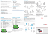
CTF 75 A (Without Fan)
CTF 90 A (Without Fan)
CTF 120 A (With Fan)
Depth: 5.6 (143)
Weight: 1.8 lbs (810 g)
Depth: 6.7 (170.4)
Weight: 5.7 lb. (2,600 g)
CTF 50 A (Without Fan)
CTF 60 A (Without Fan)
CTF 25 A
CTF 40 A
Depth: 5.6 (143)
Weight: 2.1 lbs (970 g)
Depth: 5.6 (143)
Weight: 2.9 lbs (1,300 g)
Weight: 3.3 lbs (1,500 g)
4.1
(104)
0.7 (18.5)
CTF 150 A, 200 A, 250 A
0.5 (14.0)
2.4 (60.1)
3.1 (80)
5 (127)
1.2 (30)
3.9
(100)
Fan
1.3
(32)
4.3 (108.3)
3.3 (84)
1.7 (42)
11.9
(302)
11.3
(287.4)
Dimensions are in Inches (mm)
2. Dimensions and Weights
3. Installation – Mounting

4
Installation – Mounting (cont’d.)
W
L
Model
Length
In. (mm)
Width
In. (mm)
CTF 25-40-50-60A 4.4 (112) 1.7 (44)
CTF 75-90-120A 4.4 (112) 4.4 (113)
CTF 150-200-250A 11.3 (287) 1.7 (42)
CTF Models 025A to 120A may be installed on a DIN Rail.
CTF Models 150A to 250A are rear panel mounted.
To install CTF-25A - 120A onto a DIN Rail:
• Depress the DIN mounting spring u
• Position controller on the DIN Rail at a slight angle
• Lower controller onto DIN Rail v
• Release the mounting spring
To remove from the DIN Rail:
• Depress the DIN mounting spring u
• Rotate bottom of controller off of the DIN Rail v
• Remove from DIN Rail
TURN
TURN
PRESS PRESS
1
2
2
1
Install Controller Proper position for operation Remove controller

5
This section covers the CTF wiring installation instruc-
tions for the power supply, inputs, outputs and inter-
faces.
CAREFULLY READ THE FOLLOWING WARNINGS
BEFORE INSTALLING THE INSTRUMENT!
Failure obey these warnings could create elec-
trical safety and electromagnetic compatibil-
ity problems, as well as void the warranty and
cause personal injury or death.
Electrical power supply
• The controller DOES NOT have an On/Off switch.
The user must install a switch or isolator that con-
forms to all codes and electrical safety requirements
(CE mark) to cut off the power supply upstream of
the controller. The switch must be installed in the
immediate vicinity of the controller and within reach
of the operator. A single switch can be used for mul-
tiple devices.
• The earth connection must be made with a specific
lead.
• If the product is used in applications with risk of
harm to persons or damage to machines or ma-
terials, it MUST be equipped with auxiliary alarm
device(s). It is advisable to provide the ability to
check for tripped alarms during regular operation.
DO NOT install the product in rooms with hazard-
ous (inflammable or explosive) atmosphere; it may
be connected to elements that operated in such at-
mosphere only by means of appropriate interfaces
that conform to current safety standards.
Notes on Electrical Safety and Electromagnetic
Compatibility
CE MARKING: EMC (electromagnetic compatibility)
conformity in compliance with Directive 2004/108/
CE and following modifications. Series CTF control-
lers are mainly intended for industrial use, installed on
panels or control panels of production process ma-
chines or systems. For purposes of electromagnetic
compatibility, the most restrictive generic standards
have been adopted, as shown on the tables.
LV (low voltage) conformity Directive 2006/95/CE.
EMC compliance has been verified with respect to the
information in Tables 1 and 2.
Recommended Installation for purposes of EMC
Instrument power supply
• The power supply for the electronic instrumentation
on the panels must always come directly from a cut/
off device with fuse for the instrument part.
• Electronic instrumentation and electromechanical
power devices such as relays, contactors, solenoids,
etc., MUST ALWAYS be powered by separate lines.
• When the power supply line of electronic instru-
ments is heavily disturbed by switching of SCR pow-
er groups or by motors, you should use an isolation
transformer only for the controllers, grounding its
sheathing.
• It is important for the system to be well grounded.
Voltage between neutral and ground must not be > 1
V and resistance must be < 6Ω (Ohms).
• If the grid voltage is highly unstable, use a voltage
stabilizer.
• In proximity of high frequency generators or arc
welders, use adequate grid filters.
• The power supply lines must be separate from in-
strument input and output lines.
• Supply from Class II or from limited energy sources.
Input and output connections
Before connecting or disconnecting any connection, al-
ways check that the power and control cables are isolat-
ed from voltage. Appropriate devices must be provided:
fuses or automatic switches to protect power lines.
The fuses present in the module function solely as a
protection for the CTF semiconductors.
•
Connected outside circuits must be doubly isolated.
• To connect analog or linear inputs, strain gauges,
TC, RTD, etc., you have to:
• physically separate the input cables from those
of the power supply, outputs, and power con-
nections.
• use braided and shielded cables, with sheath-
ing grounded at a single point.
Installation Notes
Use the extra rapid fuse indicated in the CTF Hardware
Instruction Manual PK533, according to the wiring
schematic examples and controller rating. Additionally,
the applications with solid state units require a safety
automatic switch to disengage the load power line dur-
ing certain alarm events.
4. Installation – Wiring

6
Table 1: EMC Emission
AC semiconductor motor controllers and conductors
for non-motor loads
EN 60947-4-3
Emission enclosure compliant in firing mode single
cycle and phase angle if external filter fitted
EN 60947-4-3 CISPR-11
EN 55011
Class A
Group 2
Table 2: EMC Immunity
Generic standards, immunity standard for
industrial environments
EN 60947-4-3
ESD immunity EN 61000-4-2
4 kV contact discharge
8 kV air discharge
RF interference immunity
10 V/m amplitude modulated
80 MHz-1 GHz
10 V/m amplitude modulated
1.4 GHz-2 GHz
Conducted disturbance immunity
10 V/m amplitude modulated
0.15 MHz-80 MHz
Burst immunity EN 61000-4-4
2 kV power line
2 kV I/O signal line
Surge immunity EN 61000-4-4/5
Power line-line 1 kV
Power line-earth 2 kV
Signal line-earth 2 kV Signal
line-line 1 kV
Magnetic fields immunity
Tests are not required.
Immunity is demonstrated
by the successful
completion of the
operating capability test
Voltage dips, short interruptions and voltage
immunity tests
EN 61000-4-11 100%U, 70%U, 40%U,
Table 3: LVD Safety
Safety requirements for electrical equipment for
measurement, control and laboratory use
EN 61010-1
UL 508
ATTENTION
This product has been designed for class A equipment. Use of the product in domestic environments may cause
radio interference, in which case the user may be required to employ additional noise mitigation methods.
EMC filters are required in Phase Angle firing mode. The filter model and current level depend on the configura-
tion and load used. The power filter MUST be connected as close as possible to the CTF. You can use a filter
connected between the power line and CTF or an LC group connected between the CTF output and the load.
The CE declaration of conformity is available on request.
5. Emission, Immunity and Safety Standards

7
6. Controller Overview
6.1 Layout
1. Supply/control connector
2. HB key calibration
3. TTL port for configuration
4. LED indicators
5. Power terminal “Line” (1/L1)
6. Power terminal “Load” (2/T1)
7. Heatsink
8. DIN rail lever
9. Switch serial line terminal
10. RS485 serial port connector
11. Address Rotary switch
CTF CST with
RS485 Communications
25 to 120 Amp Models
150 to 250 Amp Models
CTF CST with
RS485 Communications
1. “Line” terminal (1/L1)
2. Line voltage connector
3. Internal fuse protection cover
4. “Load” terminal (2/T1)
5. Cooling fan
6. TTL port for configuration by PC
7. Control input connector
8. HB key calibration
9. LED indicators
10. Input connector
11. Supply connector
12. Output connector
13. Dip Switch serial line
14. RJ10 connector serial port RS485
15. Address rotary switch

8
6.2 Cooling Fan
1. Fan
2. Intake Grill
3. Detail of insertion of fan connector in PCB
PERIODIC CLEANING
Every 6-12 months (depending on the dust level of
the installation) blow a compressed air jet downward
through the upper rectangular cooling grilles (on the
side opposite the fan). This will clean the internal heat
dissipater and the cooling fan.
IN CASE OF OVERHEAT ALARM
If periodic cleaning does not eliminate the problem, do
as follows:
a. Remove the fan support grille by detaching the two
support tabs
b. Disconnect the fan connector from the board
c. Check the condition of the fan
d. Clean or replace the fan
NOTE: Ensure that the air flow arrow on the fan is
pointing towards the heat sink e Insert the connec-
tor into the board
f. Insert the fan support grille until it attaches
g. Power up the device and check fan rotation when at
least one load is on
Before and during the inspection/
maintenance cut power to the fan
controller and verify that the system
is isolated for operator safety.

9
6.3 Replacing Internal Fuse (Option for CTF 150-250A)
Before and during the inspection/maintenance cut power to the fan controller and
verify that the system is isolated for operator safety.
• Remove the cover fastening screw (1)
• Remove the cover as indicated by the arrow (2)
• The fuse (3) is now visible
• Loosen the two fuse fastening nuts with a wrench
(13mm on CTF 150, 17mm on CTF 200-250)
• It is not necessary to remove the nuts entirely. The
fuse may be extracted per the arrows (4) and (5).
• Insert the new fuse as indicated by the arrows (6,7)
WARNING: the washer must remain between
the nut and the fuse (NOT under the fuse).
• Fasten the two nuts (3-4 Nm/2.2-3.0 ft. lb.) with
torque wrench
• Carefully replace the cover. Pay particular attention
to the lower connection teeth
• Secure the cover with the cover fastening screw

10
7. Connections and Indication
7.1 Input & Output Connections (CTF 25 - 120 A)
Syncronous output for
Master/Slave connection
Alarm output
(solid state relay - HB option)
Key HB
Green Led (RUN)
Yellow Led (STATUS)
Red Led (Alarm output HB)
Yellow Led (Status digital input)
Led:
Green = SCR ON
Y
ellow = Temperature OVER
1/L1
LINE connection
3/L2
Reference connection
of line voltage
Earth Ground
2/T1
LOAD connection
Fixing screw
at heatsink
Fixing screw
at heatsink
J1
Power supply /control
connector
Power supply terminal 24Vac/Vdc
Digital input (PWM input)
Potentiometer output power supply (+5Vdc
)
Input control signal (+)
(GND)
Top view
WITHOUT Modbus Option
Key HB
J2
TTL port for
Port Configuration
Top view
WITH Modbus Option
Key HB
J3, J4
RJ10 connectors
RS485 serial line
Modbus
Switch for serial line
Address x 10
Address x 1

11
7.2 Input & Output Connections (CTF 150 - 250 A)
Bottom View Without
Modbus RS485 Option
Bottom View WITH
Modbus RS485 Option
2/T1
Load
Connection
Fan
Protection
Grill
J5
Configuratiom
TTL Port
2/T1
Load
Connection
J6, J7
RJ10 connector
serial RS485 Modbus
Dip Switch
serial line
Top View
Fan
Protection
Grill
1/L1
Line Connection
Line voltage
reference connection
J8
3/L2
n.c.
RUN ...................................(Green)
STATUS .............................(Yellow)
ALARM HB ......................(Red)
DIGITAL INPUT STATUS (Yellow)
ON SCR............................(Green)
OVER Temperature...........(Yellow)
J8
Line Voltage
Connector
Front Cover
Fastener
(Fuse Access)
1/L1
Line
Connection
Outputs
Supply
Status LEDs
Digital Input
Key HB
Address Rotary
Switch (Optional)
Analog Control
Input Connector
2/T1
Load
Connection
J1
HB OUT Switch (Optional)
OUT Master (7 V)
GND
J2
24 Vac/dc
24 Vac/dc
Earth
J3
n.c.
n.c.
+ INDIG (PWM input)
GND
J4
OUT +5V (Potentiometer)
+ IN
SHUNT – mA
GND

12
7.3 LED Logic
7.4 Connections
7.4.1 CTF 25 - 120 A
Description of LED’s
LED Description Color
RUN
Flashing during normal operation
Green
On steadily: according to Firmware setting (see Software manual)
STATUS
Off : during normal operation
Yellow
On : according to Firmware setting (see Software manual)
ALARM
State HB alarm output / Power Fault Alarm / Fuse Open Red
DI
Digital Input Status Yellow
ON / OVER TEMP
Green: SCR on Green
Yellow: ON, SCR overtemperature alarm Yellow
The state of the LEDs matches the corresponding parameter, except in the following special cases:
- LED 1 (green) + LED 2 (yellow) both flashing rapidly: autobaud is in progress
- LED 2 (yellow) flashing rapidly: SSR temperature sensor broken or SSR Over Heat or Reversed Phase Error
or Fuse_open (CTF 150 to 250 A)
or Short_Circuit_Current or Line-Load Terminals Over Heat (CTF 150 to 250 A)
CONNECTOR J1 CTF 25-120 A
(CONTROL)
CONNECTOR J1 CTF 25-120A
PIN Name Description
1
OUT AL HB OUT Alarm Switch (HB)
2
3
OUT_Master Control output Slave (+7V)
4
GND GND Control analog input
5
+ IN + Control analog input
6
+5V_POT Output potentiometer
7
IN_DIG Digital input & PWM Input
8
24 V Supply
Supply 18 to 32 Vac/Vdc
9
24 V Supply
0.2 - 2.5mm
2
24-14 AWG
0.25 - 2.5mm
2
23-14 AWG

13
7.4.2 CONNECTOR J1 CTF 150-250 A OUTPUT
CONNECTOR J1, CTF 150-250 A
CONNECTOR J1, J4 CTF 150-250 A
PIN Name Description
1
OUT AL HB
Contact output N.O.
Alarm HB
2
3
+OUT_Master
Output 7 Vdc for control
slave module
4
GND GND output OUT_Master
0.2 - 2.5 mm
2
24-14 AWG
0.25 - 2.5 mm
2
23-14 AWG
7.4.3 CONNECTOR J2 CTF 150-250 A 24 V SUPPLY
CONNECTOR J2 CTF 150-250 A
(24 V SUPPLY)
CONNECTOR J2 CTF 150-250 A
(24 V SUPPLY)
0.2 - 2.5 mm
2
24-14 AWG
0.25 - 2.5 mm
2
23-14 AWG
PIN Name Description
1
24 Vdc/Vac
24 V Supply
2
24 Vdc/Vac
3
EARTH Earth EMC
CONNECTION SCHEMATIC J2 FOR CTF 150-250 A
CONNECTION SCHEMATIC J1 FOR CTF 150-250 A

14
7.4.4 J3 CTF 150-250 A DIGITAL OUTPUT
PIN Name Description
1
--- Not Connected
2
--- Not Connected
3
+IN_DIG Digital Input (& PWM Input)
4
GND 24 V Supply
0.14 - 0.5 mm
2
28-20 AWG
0.25 - 2.5 mm
2
23-20 AWG
7.4.5 CONNECTOR J4 CTF 150-250 A ANALOG INPUT
0.2 - 2.5 mm
2
24-14 AWG
0.25 - 2.5 mm
2
23-14 AWG
CONNECTOR J3 CTF 150-250 A
(DIGITAL INPUT)
CONNECTOR J3 CTF 150-250 A
(DIGITAL INPUTS)
CONNECTOR J4 CTF 150-250 A
(CONTROL ANALOG INPUT)
PIN Name Description
1
OUT AL HB Supply Output 5 V Potentiometer
2
+IN Control Voltage Input
3
SHUNT Shunt for Input mA
4
GND GND Control Signal
CONNECTION SCHEMATIC J4 FOR CTF 150-250 A
CONNECTION SCHEMATIC J3 FOR CTF 150-250 A

15
7.5 RECOMMENDED GAUGES
CTF Current
Level Terminal Cable Wire Wire Terminal Tightening Torque / Tool
25A 1/L1, 2/T1, PE
4 mm
2
10 AWG
Wire terminal / Eye D. 6mm
2.5 Nm / Phillips screwdriver
PH2 - PH3
40A 1/L1, 2/T1, PE
10 mm
2
7 AWG
Wire terminal / Eye D. 6mm
2.5 Nm / Phillips screwdriver
PH2 - PH3
50A 1/L1, 2/T1, PE
10 mm
2
7 AWG
Wire terminal / Eye D. 6mm
2.5 Nm / Phillips screwdriver
PH2 - PH3
60A 1/L1, 2/T1, PE
16 mm
2
5 AWG
Wire terminal / Eye D. 6mm
2.5 Nm / Phillips screwdriver
PH2 - PH3
75A 1/L1, 2/T1, PE
25 mm
2
3 AWG
Wire terminal / Eye D. 6mm
2.5 Nm / Phillips screwdriver
PH2 - PH3
90A 1/L1, 2/T1, PE
35 mm
2
2 AWG
Wire terminal / Eye D. 6mm
2.5 Nm / Phillips screwdriver
PH2 - PH3
120A 1/L1, 2/T1, PE
50 mm
2
1/0 AWG
Wire terminal / Eye D. 6mm
2.5 Nm / Phillips screwdriver
PH2 - PH3
- 3/L2 (Ref. Vline)
0.25 ...2.5 mm
2
23...14 AWG
Wire terminal tip
0.5 ...0.6 Nm / Screwdriver
blade 0.6 x 3.5 mm
150A 1/L1, 2/T1
70 mm
2
2/0 AWG
Wire stripped for 25 mm or with
crimped pre-insulated terminal
tube
6 Nm / No. 6 hex head wrench
200A 1/L1, 2/T1
95 mm
2
4/0 AWG
Wire stripped for 25 mm or with
crimped pre-insulated terminal
tube
6 Nm / No. 6 hex head wrench
250A 1/L1, 2/T1
120 mm
2
250 KCMIL
Wire stripped for 25 mm 6 Nm / No. 6 hex head wrench
- 3/L2 (Ref. Vline)
0.25 ...2.5 mm
2
23...14 AWG
Wire stripped for 8 mm or with
tag terminal
0.5 ...0.6 Nm / Flat-head
screwdriver tip 0.6 x 3.5 mm
NOTE: Cables must be Copper “Stranded Wire” or “Compact-Stranded Wire” type with max. operating temp. 60/75°C

16
7.6 TTL CONFIGURATION PORT (CTF STANDARD)
7.7 MODBUS RS485 PORTS (OPTION)
Connector J2 CTF 25-120A - Connector J5 CTF 150-250A
Connector S1/S2
RJ10 4-4 pin Nr. Pin Name Description Note
4
3
2
1
1 GND Ground
Use of this port requires custom USB
to TTL Configuration Cable.
Chromalox Part No. 0149-50090
2 RX_TTL Data reception TTL from CTF
3 TX_TTL Data transmission TTL to CTF
4 (Reserved) DO NOT connect
Cable type: flat telephone cable for pin 4-4 conductor 28 AWG
Connectors J3, J4 CTF 25-120A and Connectors J6, J7 CTF 150-250A
Connector S1/S2
RJ10 4-4 pin Nr. Pin Name Description Note
4
3
2
1
1 GND1 (**)
Use of these ports requires custom
USB to RS485 configuration cable.
(Chromalox Part No. 0149-50091
(*) Insert the RS485 line
termination in the last device on
the Modbus line, see dip-switches.
(**) Connect the GND signal
between Modbus devices with a
line distance > 100 m.
2 Tx/Rx+ Data reception/transmission (A+)
3 Tx/Rx+ Data reception/transmission (B-)
4 +V (reserved)
Cable type: flat telephone cable for pin 4-4 conductor 28 AWG

17
8. Load Connection Example
PROCESS
CONTROLLER
I
2
t FUSE
INST.
FUSE
FUSE OPTION NOTE:
I
2
t Fuse needed only for controller
with fusing option code = 0
PROCESS
CONTROLLER
I
2
T FUSE
INST. FUSE
CTF 25-120 A for 1 single-phase load, single-phase line (L1-N) or open delta (L1-L2)
CTF 150A -250 A 1 single-phase load, single-phase line L1-L2/N
Fuse Note:
I
2
T Fuse: Rapid Blow Fuse.
Inst. Fuse: Low amperage, fast-acting
“instrumentation” fuse.
See Fuse & Fuse Holder’s section.
The I
2
T fuses are designed to protect the
SCR from Faults on the Load Connection
side. They are NOT intended to provide
branch circuit or wire protection.
The I
2
T fuses are designed to pro-
tect the SCR from Faults on the
Load Connection side. They are
NOT intended to provide branch
circuit or wire protection.
Fuse Note:
I
2
T Fuse: Rapid Blow Fuse.
Inst. Fuse: Low amperage, fast-acting
“instrumentation” fuse.
See Fuse & Fuse Holder’s section.

18
CTF 25-120 A for 1 single-phase load with transformer single-phase line (L1-N) or open delta (L1-L2) .
CTF 150A -250 A for 1 single-phase load with transformer single-phase line L1-L2/N
PROCESS
CONTROLLER
I
2
t FUSE
INST. FUSE
PROCESS
CONTROLLER
I
2
t FUSE
INST. FUSE
FUSE OPTION NOTE:
I
2
t Fuse needed only for controller
with fusing option code = 0
Fuse Note:
I
2
T Fuse: Rapid Blow Fuse.
Inst. Fuse: Low amperage, fast-acting
“instrumentation” fuse.
See Fuse & Fuse Holder’s section.
The I
2
T fuses are designed to pro-
tect the SCR from Faults on the
Load Connection side. They are
NOT intended to provide branch
circuit or wire protection.
The I
2
T fuses are designed to pro-
tect the SCR from Faults on the
Load Connection side. They are
NOT intended to provide branch
circuit or wire protection.
Fuse Note:
I
2
T Fuse: Rapid Blow Fuse.
Inst. Fuse: Low amperage, fast-acting
“instrumentation” fuse.
See Fuse & Fuse Holder’s section.
/