Page is loading ...

Title
Assembly Instructions
thermoMETER CTM-4
MICRO-EPSILON MESSTECHNIK GmbH & Co. KG
Koenigbacher Str. 15
94496 Ortenburg / Germany
Tel. +49 8542 / 168-0 / Fax +49 8542 / 168-90
e-mail [email protected]
www.micro-epsilon.com
Your local contact:
www.micro-epsilon.com/contact/worldwide/
X9771190.01-A012021HDR
Warnings
Connect the power supply and the display/output device according to the
safety regulations for electrical equipment.
> Risk of injury, damage to or destruction of the sensor and/or the controller
Avoid shocks and impacts to the sensor and controller.
> Damage to or destruction of the sensor and/or the controller
Avoid rough mechanical force on the sensor.
> Damage to or destruction of the sensor
The supply voltage must not exceed the specified limits.
> Damage to or destruction of the sensor and/or the controller.
Protect the sensor cable against damage.
> Destruction of the sensor, failure of the measuring device
Never fold the sensor cable and do not bend it in tight radii. The minimum
bending radius is 14 mm (static). Dynamic movement is not permitted.
> Damage to the sensor cable, failure of the measuring device
Avoid exposure of sensor (both optics and housing) to cleaning agents that
contain solvents.
> Damage to or destruction of the sensor
Avoid abrupt changes of the operating temperature.
> Inaccurate or incorrect measurements
Notes on CE Marking
The following apply to the thermoMETER CTM-4 measuring system:
- EU Directive 2014/30/EU
- EU Directive 2011/65/EU
The sensor satisfies the requirements if the guidelines in the operating instruc-
tions are maintained in installation and operation.
Proper Environment
- Protection class:
Sensor: IP65 (NEMA 4)
Controller: IP65 (NEMA 4)
- Operating temperature:
Sensor: 0 ... +70 °C (+32 ... +158 °F)
Controller: 0 ... +70 °C (+32 ... +158 °F)
- Storage temperature:
Sensor: -40 ... +85 °C (-40 ... +185 °F)
Controller: -40 ... +85 °C (+32 ... +158 °F)
- Humidity: 10 ... 95 %, non-condensing
Unpacking/Included in Delivery
- 1 thermoMETER CTM-4 sensor and sensor cable
- 1 Controller
- 1 Mounting nut
- 1 Assembly instructions
- 1 Micro-USB cable
You can download a PDF of the detailed operating instructions from our
website:
http://www.micro-epsilon.de/download/manuals/man--thermoMETER-CT--en.pdf
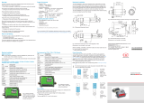
Mechanical Installation
The thermoMETER CTM-4 sensors feature a metric M12x1-thread and can be
directly installed into existing mounting devices by using the sensor thread or
by using the mounting nut included. Various mounting brackets are available
as accessories to facilitate the alignment of the sensor to the object, see also
operating instructions.
WS14
M12x1
max. 3
(.12)
32 (1.26)
Ø14
(.55 dia.)
10
(.39)
Ø10
(.39 dia.)
Ø28
(1.1 dia.)
Dimensional drawing of thermoMETER CTM-4 sensor, dimensions in mm, not
to scale
i
The sensor and the controller cannot be exchanged arbitrarily within
the thermoMETER CT sensor group.
Electrical Installation
Cable Connections
For the electrical installation of the thermoMETER CTM-4, please open
at first the cover of the controller (4 screws).
The screw terminal connections for connecting the cables are located in the
bottom of the controller.
Pin Assignments for CTM-4 Models
Pin Explanation
+8 ... 30 VDC Power supply
GND Power supply ground (0 V)
GND Internal input and output ground (0 V)
AL2 Alarm 2 (open collector output)
OUT-1 Analog output mA, mV, TCK
OUT-2 Analog output mA, mV, TCK
I/O1, I/O2, I/O3 Inputs and outputs
GND Ground (0 V)
PINK 3 VDC, switchable for laser sighting tool
GRAY Ground for PINK pin
BROWN Temperature probe for sensor (NTC)
WHITE Sensor ground
GREEN Power supply (sensor)
YELLOW Detector signal
Slide switch, see
also chapter
Ground Connection
Power Supply
Please use a power supply unit with an output voltage of 8 ... 30 VDC that
provides at least 100 mA current. Residual ripple should be no more than
200 mV.
Never apply voltage to the analog outputs.
> Destruction of the output
thermoMETER CTM-4 is not a two-wire sensor!
Ground Connection
On the left-hand side of the mainboard, you will find a slide
switch which connects the ground terminals (GND supply volt-
age/output) to the housing ground of the controller by default.
To prevent ground loops and related signal interference, it may
be necessary to separate this connection in an industrial envi-
ronment. This requires to change the slide switch position.
Slide switch on the mainboard
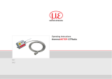
70 (2.76)
122 (4.8)
13 (.51)
WS14
WS12
23 (.91)
47 (1.85)
110 (4.33)
4 (.16)
4 (.16)
89 (3.50)
M12x1.5
Ø4.5
(.18)
4
(.16)
30
(1.18)
4 (.16)
Dimensional drawing of controller, dimensions in mm, not to scale
Shortening the Sensor Cable
With the thermoMETER CTM-4, the sensor cable can be shortened if neces-
sary.
i
Shortening the cable will cause an additional measuring error of about
0.1 K/m.
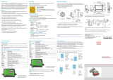
Ratio D = Distance From Device Front Edge to Measuring Object/S = Spot Size
The size of the object to be measured and the optical resolution of the IR thermometer determine the maximum distance between sensor and object. To avoid
measuring errors, the measuring object should completely fill the field of vision of the sensor's optical system. This means, the spot must always be at least as
large as or smaller than the measuring object.
CTM-4SF10
D:S = 10:1 6.5 14.9 23.3 31.6 40 51.6 63.3 74.9 86.5 S
Distance (mm) 0 100 200 300 400 500 600 700 800 D
Optical specifications
Open CTM-4 controller
with terminal connections

Sensor Cable Installation
Mounting
The controller’s M12x1.5 cable gland is suitable for cables with an outer
diameter of 3 to 5 mm.
Remove the cable insulation (40 mm power supply,
50 mm signal outputs, 60 mm function inputs).
Shorten the shielding braid to approx. 5 mm and unravel the shielding
wires.
Remove approx. 4 mm of the individual core insulations and tin the core
ends.
Push the compression screw, washers and the cable screw connec-
tion’s rubber seal one after another onto the prepared cable end.
Spread the shielding braids and affix the cable shield between two metal
discs.
Insert the cable into the cable gland until the stop.
Tightly screw on the cap.
Individual cores can now be attached to the appropriate screw terminal con-
nections based on their colors.
Pressing screw
Shield
Metal washer
Rubber washer
Cable installation
i
Only use shielded cables!
The sensor must be grounded!
Inputs and Outputs
Analog Outputs
You can freely choose output 1 or 2 with the thermoMETER CTM-4.
Never apply voltage to the analog outputs.
The thermoMETER CTM-4 is not a two-wire sensor!
> Destruction of the output
Output channel 1 / 2 (both channels)
This output is used to output the object temperature. The programming keys
are used to select the output signal. Output channel 1 can also be pro-
grammed as an alarm output by using the CompactPlus Connect software.
Output signal Range Connection pin on CTM-4 board
Voltage 0 ... 5 V OUT-mV/mA
Voltage 0 ... 10 V OUT-mV/mA
Current 0 ... 20 mA OUT-mV/mA
Current 4 ... 20 mA OUT-mV/mA
Thermocouple TC K OUT-TC
i
Please note that, depending on the output used, different connection
pins (OUT-mV/mA or OUT-TC) are used.
I/O Pins
The thermoMETER CTM-4 has three I/O pins, which can be programmed as
output (digital) as well as input (digital or analog) using the CompactPlus
Connect software. The following functions are possible:
Function I/O Pin is a Description
Alarm Digital output Open-collector output/ Definition as
High or Low alarm via normally open/
normally closed in the software dialog
Valid Low Digital input The output follows the object tempera-
ture as long as a Low level is present at
the I/O pin. If there is no more Low level,
the last value is held.
Valid High Digital input The output follows the object tempera-
ture as long as a High level is present
at the I/O pin. If there is no more High
level, the last value is held.
Hold Low-High Digital input With rising edge at the I/O pin, the last
value is held.
Hold Low-High Digital input With falling edge at the I/O pin, the last
value is held.
Reset Low Digital input Resetting the search for the maximum or
minimum (High-Low)
External emis-
sivity
Analog input The emissivity can be set at the I/O pin
via a 0-10 V signal (scaling possible via
software).
Uncommitted
value
Analog input Display of an uncommitted value
Laser at Low Digital input Switch on laser (Low signal)
Laser at High Digital input Switch on laser (High signal)
External ambi-
ent compensa-
tion
Analog input Voltage at the I/O pin [0 – 10 V; scalable
range] sets the ambient temperature.
External trans-
mitted radiation
Analog input Voltage at the I/O pin [0 – 10 V; scalable
range] sets the ambient temperature.
Low/High level: adjustable via software
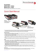
CompactPlus Connect Software
You can find the CompactPlus Connect software online on our website at:
https://www.micro-epsilon.de/download/software/thermoMETER-Compact-
PlusConnect/.
Download the software, unzip it, open the program and start the CDset-
up.exe.
Please follow the instructions in the wizard until the installation has been
completed.
After installation, the CompactPlus Connect software is available on your
desktop (as a program icon) and in the start menu under:
[Start]\Programs\CompactPlus Connect.
The downloaded software package includes a detailed software description.
Uninstalling
If you want to uninstall the software, please use the Uninstall function in
the Windows settings.
System Requirements
- Windows 7, 8 and 10
- At least 128 MByte RAM
- USB interface
- Hard drive with at least 30 MByte storage space
Main Functions
- Visual depiction and
recording of temperature
measurements for later
analysis and documenta-
tion
- Setting all sensor param-
eters and remote sensor
monitoring
- Programming signal pro-
cessing functions
- Scaling outputs and setting
parameters for function
inputs
Operation
After the supply voltage is applied, the sensor starts an initialization routine
and shows INIT on the display for a few seconds. Next, the object tempera-
ture is displayed. The color of the display lighting changes depending on the
alarm settings.
Configuring the Sensor
The programming keys , and allow the configuration of the sensor
on site. The display shows the current measurement or the selected func-
tion. The key moves you to the desired function, and change the
function parameters - a settings change is applied immediately. If no key
is pressed for more than 10 seconds, the display automatically switches to
showing the calculated object temperature (according to the selected signal
processing).
Mode
Auf
Ab
When the key is pressed, you automatically
reach the last function called.
The maximum search and minimum search
signal processing functions cannot be selected
concurrently.
Display and programming keys
Restoring Factory Setting
To reset the thermoMETER CTM-4 to factory-set parameters, first press
the key and then the key and hold both for 3 seconds.
For confirmation, RESET appears on the display.
Digital Interfaces
The description of the optional digital interfaces is available in the operating
instructions. The following interfaces are available: RS232, RS485 or Ethernet.
Alarms
Output channels 1 and 2
To be activated, the corresponding output channel must be switched to digital
mode. You can do so only by using the CompactPlus Connect software.
i
You can freely choose between both outputs with the thermoMETER
CTM-4. You can select analog mA/mV, Alarm mA/mV and TCK.
Visual alarms
These alarms cause the color of the LCD display to change and are available
by using the optional relay interface. Alarm 2 can additionally be used on pin
AL2 (on the mainboard) as open collector output [24 V/50 mA].
The factory default definitions of the alarms are:
Alarm 1 Normally closed/low alarm
Alarm 2 Normally open/high alarm
Both alarms affect the color settings of the LCD display:
BLUE Alarm 1 active
RED Alarm 2 active
GREEN No alarm active
For advanced settings, such as defining them as low or high alarm (by
changing normally open/closed) or selecting the signal source [T
Proc
, T
Head
,
T
Box
], a digital interface (e.g., USB, RS232) and the CompactPlus Connect
software are required.
i
With the thermoMETER CTM-4, visual alarms are independent of the
alarm settings. You can define those in the CompactPlus Connect
software.
Function Parameters
Display Mode (example) Settings range
TPROC 320.9 Process temperature
(after signal processing) [320.9 °C]
Cannot be changed
T INT 50.1 Detector temperature [50.1 °C] Cannot be changed
T BOX 38.6 Controller temperature [38.6 °C] Cannot be changed
EMISS 1.000 Emissivity [1.000] 0.100 ... 1.100
Trans 1.000 Emissivity [1.000] 0.100 ... 1.100
AVG 0.020 Mean signal output [0.020 s] 0.100 ... 1.100
HOLD OFF OFF/ PEAK/ VALL/
APEAK/ AVALL
0…65 s
(65 = infinite)
Initial temperature…
End temperature
Hysteresis setting in
°C/°F
H TIM PEAK/ VALL
H TH APEAK/ AVALL
H HY APEAK/ AVALL
U °C Temperature unit [° C] °C/ °F
M 01 Multidrop address [1] (only with
RS485 interface)
RS422 mode
01 … 32
RS422 (Press
button at M01)
BAUD 115.2K Baud rate in kBaud [115] 115.2 / 921.6 kBaud
S ON Laser sighting ON/OFF
Peak Picker Function
For an acquisition of fast hotspots (response time 90 µs), the averaging time
must be set to 0.0 s. In addition, the HOLD function must be set to PEAK.
/