Page is loading ...

Title
Assembly Instructions
thermoMETER CTL
MICRO-EPSILON MESSTECHNIK GmbH & Co. KG
Koenigbacher Str. 15
94496 Ortenburg / Germany
Tel. +49 8542 / 168-0 / Fax +49 8542 / 168-90
e-mail [email protected]
www.micro-epsilon.com
X9771197-A022030HDR
*X9771197-A02*
Intended Use
The thermoMETER CTL is designed for use in industrial and laboratory appli-
cations. It is used for non-contact temperature measurement.
The system must only be operated within the limits specified in the technical
data, see operating instructions, Chap 2. The system must be used in such a
way that no persons are endangered or machines are damaged in the event
of malfunction or total failure of the system. Take additional precautions for
safety and damage prevention in case of safety-related applications.
Warnings
Connect the power supply and the display/output device according to the
safety regulations for electrical equipment.
> Risk of injury, damage to or destruction of the sensor and/or the controller
Avoid shocks and impacts to the sensor and the controller.
> Damage to or destruction of the sensor and/or the controller
Avoid rough mechanical force on the sensor.
> Damage to or destruction of the sensor
The supply voltage must not exceed the specified limits.
> Damage to or destruction of the sensor and/or controller.
Protect the sensor cable against damage.
> Destruction of the sensor, failure of the measuring device
Never fold the sensor cable and do not bend it in tight radii. The minimum
bending radius is 14 mm (static). Dynamic movement is not permitted.
> Damage to sensor cable, failure of the measuring device
Avoid exposure of sensor (both optics and housing) to cleaning agents that
contain solvents.
> Damage to or destruction of the sensor
Avoid abrupt changes in ambient temperature.
> Inaccurate or incorrect measurements
Laser Class
The thermoMETER CTL sensor works with a double laser sight at a wave-
length of 635 nm (visible/red).
The warning sign below is attached to the controller:
THIS PRODUCT COMPLIES WITH
21 CFR 1040.10AND 1040.11
EXCEPT FOR CONFORMANCE
WITH IEC 60825-1 ED. 3.,
AS DESCRIBED IN LASER NOTICE NO. 56,
DATED MAY 8, 2019.
COMPLIES WITH 21 CFR 1040.10 AND
1040.11 EXCEPT FOR CONFORMANCE
WITH IEC 60825-1 ED. 3.,
AS DESCRIBED IN LASER NOTICE NO. 56,
DATED MAY 8, 2019.
LASER LIGHT
DO NOT STARE INTO BEAM
CLASS 2 LASER
< 1 mW / 500 - 650 nm
EN 60825 1: 2014
COMPLIES WITH 21 CFR 1040.10 AND
1040.11 EXCEPT FOR CONFORMANCE
WITH IEC 60825-1 ED. 3.,
AS DESCRIBED IN LASER NOTICE NO. 56,
DATED MAY 8, 2019.
LASER LIGHT
DO NOT STARE INTO BEAM
CLASS 2 LASER
< 1 mW / 500 - 650 nm
EN 60825 1: 2014
COMPLIES WITH 21 CFR 1040.10 AND
1040.11 EXCEPT FOR CONFORMANCE
WITH IEC 60825-1 ED. 3., AS
DESCRIBED IN LASER NOTICE NO. 56,
DATED MAY 8, 2019.
LASER LIGHT
DO NOT STARE INTO BEAM
CLASS 2 LASER
< 1 mW / 500 - 650 nm
EN 60825 1: 2014
Do not look deliberately into the laser beam! Close
your eyes, or immediately turn away if the laser beam
hits the eye.
Notes on CE Marking
The following apply to the thermoMETER CTL measuring system:
- EU Directive 2014/30/EU
- EU Directive 2011/65/EU, “RoHS” Category 9
The sensor satisfies the requirements if the guidelines in the operating instruc-
tions are maintained in installation and operation.
Proper Environment
- Protection class:
Sensor: IP 65 (NEMA 4)
Controller: IP 65 (NEMA 4)
- Ambient temperature:
Sensor: -20 °C ... +85 °C
(-4 °F ... +185 °F)
(+50 °C (+122 °F) when laser is on)
Controller: 0 ... +85 °C (+32 °F ... +185 °F)
1
- Storage temperature:
Sensor: -40 °C ... +85 °C (-40 °F ... +185 °F)
Controller: -40 °C ... +85 °C (-40 °F ... +185 °F)
- Humidity: 10 ... 95 %, non-condensing
Unpacking/Included in Delivery
- 1 thermoMETER CTL sensor and sensor cable
- 1 Controller
- 1 Mounting nut and fixed mounting bracket
- 1 Assembly instructions
1) With temperatures < 0 °C, display function is not guaranteed any more.
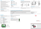
Mechanical Installation
The CTL features a metric M48x1.5 thread and can be directly installed into
existing mounting devices by using this thread or by using the hexagonal nut
(default) and fixed mounting bracket (default).
Avoid rough mechanical force on the sensor.
> Destruction of the system
85.5
(3.37)
Ø49.3
(1.94 dia.)
M48x1.5
WS 52
30
(1.18)
8 (.31)
Cable gland
M 12 x 1.5
Ø55
(2.17 dia.)
100 (3.94)
Ø50
(1.97 dia.)
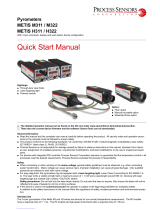
Fig. 1 Dimensional drawing of CTL sensor, dimensions in mm, not to scale
The optical path of the beam must be free of any obstructions.
> Deviation in measurement, inaccurate measured result
Please enable the integrated double laser to precisely align the sensor with
the object; see operating instructions.
You can download a PDF of the detailed operating instructions from our
website:
http://www.micro-epsilon.de/download/manuals/man--thermoMETER-CTL--en.pdf
Electrical Installation
Cable Connection
The default version is shipped with sensor cables (connection between sen-
sor and controller).
To connect the thermoMETER CTL, open the controller cover (4 screws).
The screw terminal connections for connecting the cables are located in the
bottom of the controller.
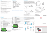
Pin Assignments for CTL/CTLF/CTLC/CTLG Models
Pin Explanation
+8 - 36 VDC Power supply
GND Power supply ground (0 V)
GND Internal input and output ground (0 V)
OUT-AMB Analog output for sensor temperature (mV)
OUT-TC Analog output for thermocouple (J or K)
OUT-mV/mA Analog output for object temperature (mV or mA)
F1-F3 Function inputs
AL2 Alarm 2 (open collector output)
3V SW PINK/power supply for laser (+)
GND GRAY/power supply for laser (-)
BROWN Temperature probe (sensor) (NTC)
WHITE Ground sensor
GREEN Power supply sensor
YELLOW Detector signal
Fig. 4 Open CTL/CTLF/
CTLC/CTLG controller with
terminal connections
Pin Assignments for CTLM Models
Pin Explanation
+8 ... 36 VDC Power supply
GND Power supply ground (0 V)
GND Internal input and output ground (0 V)
AL2 Alarm 2 (open collector output)
OUT-TC Analog output for thermocouple (J or K)
OUT-mV/mA Analog output for object temperature (mV or mA)
F1-F3 Function inputs
GND Ground (0 V)
3V SW PINK/power supply for laser (+)
GND PINK/power supply for laser (-)
BROWN Temperature probe for sensor (NTC)
WHITE Sensor ground
GREEN Power supply (sensor)
YELLOW Detector signal
Fig. 5 Open CTLM controller
with terminal connections
Power Supply
Please use a power supply unit with an output voltage of 8 - 36 VDC that
provides at least 160 mA current. Residual ripple should be no more than
200 mV.
Never apply voltage to the analog outputs.
> Destruction of the output
thermoMETER CTL is not a two-wire sensor!
Ground Connection
A plug connector (jumper) is located on the bottom of the motherboard.
Depending on the position, the ground terminals (GND supply voltage/output)
are connected to the housing ground of the controller, see Fig. 6, see Fig. 8.
To prevent ground loops and related signal interference, it may be necessary
to separate this connection in an industrial environment.
To do so, remove the board in order to switch the jumper on the back of
the board by removing the 2 screw connections.
Please push the jumper into the appropriate position, see Fig. 7, see
Fig. 9.
i
When using the thermocouple output, separation of the ground con-
nection GND - housing is recommended in principle.
Fig. 6 Plug
connector
(jumper),
GND to
housing;
CTL, CTLF,
CTLC, CTLG
models
Fig. 7 Plug
connector
(jumper),
GND - open;
CTL, CTLF,
CTLC, CTLG
models
Fig. 8 Plug
connector
(jumper),
GND to
housing;
CTLM models
Fig. 9 Plug
connector
(jumper),
GND - open;
CTLM models
Position
Cable gland
Board
110 (4.33)
92 (3.62)
4 (.16)
4 (.16)
70 (2.76)
89 (3.50)
max. 120 (4.72)
4
(.16)
4
(.16)
23 (.91)
47 (1.85)
22 (.87)
24
(.94)
30
(1.18)
M12x1.5
23
(.91)
13
(.51)
13 (.51)
Ø4.5
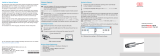
Fig. 2 Dimensional drawing of controller, dimensions in mm, not to scale
The mounting bracket is included in the scope of delivery.
57
(2.24)
Ø
48.5
(1.91 dia.)
50
(1.97)
49 (1.93)
60 (2.36)
4 (.16)
R3.3
R28
60°
46.27
(1.82)
87 (3.43)
13.73
(.54 dia.)
R5
90°
135°
Ø60
(2.36 dia.)
Ø6.5
(.26 dia.)
Fig. 3 Dimensional drawing of mounting bracket, dimensions in mm, not to
scale
The sensor can be adjusted on 2 axes by using the adjustable mounting
bracket; see also operating instructions, Optional Accessories.

Sensor Cable Installation
The controller’s M12x1.5 cable gland is suitable for cables with an outer
diameter of 3 to 5 mm.
Remove the cable insulation (40 mm power supply, 50 mm signal out-
puts, 60 mm function inputs).
Shorten the shielding braid to approx. 5 mm and unravel the shielding
wires.
Remove approx. 4 mm of the individual core insulations and tin the core
ends.
Push the compression screw, washers and the cable screw connection’s
rubber seal one after another onto the prepared cable end according to
the figure, see Fig. 10.
Spread the shielding braids and affix the cable shield between two metal
discs.
Insert the cable into the cable gland until the stop.
Tightly screw on the cap.
Individual cores can now be attached to the appropriate screw terminal con-
nections based on their colors.
Metal washer
Rubber washer
Pressing screw
034J - PQKE - 0JKH
Shield
i
Only use shielded ca-
bles! The sensor must
be grounded!
Fig. 10 Cable installation
Inputs and Outputs
Analog Outputs
The thermoMETER CTL features 1 or 2 output channels.
Never apply voltage to the analog outputs.
The thermoMETER CTL is not a two-wire sensor!
> Destruction of the output
Output channel 1
This output is used to output the object temperature. The programming keys
are used to select the output signal. Output channel 1 can also be pro-
grammed as an alarm output by using the CompactConnect software.
Output signal Range Connection pin on CT board
Voltage 0 ... 5 V OUT-mV/mA
Voltage 0 - 10 V OUT-mV/mA
Current 0 - 20 mA OUT-mV/mA
Current 4 - 20 mA OUT-mV/mA
Thermocouple TC J OUT-TC
Thermocouple TC K OUT-TC
i
Please note that, depending on the output used, different connection
pins (OUT-mV/mA or OUT-TC) are used.
Output channel 2 (only for CTL, CTLG models)
The sensor temperature [-20 ... 180 °C as 0 ... 5 V or 0 ... 10 V signal] is output
to the OUT AMB connection pin. Output channel 2 can also be programmed
as an alarm output by using the software. Here the object temperature
TObject or controller temperature TBox can also be used as an alarm source
instead of the sensor temperature THead.
Digital Interfaces
The description of the optional digital interfaces is available in the operating
instructions. The following interfaces are available: USB, RS232, RS485, Profi-
bus, CAN BUS interface, Ethernet, Modbus RTU
Function Inputs
The three function inputs F1 to F3 can only be programmed by using the
CompactConnect software.
Function inputs Description
F1 (digital) Trigger (a 0 V level at F1 resets holding functions)
F2 (analog)
External emissivity [0 - 10 V: 0 V
e= 0.1; 9 V
e= 1; 10 V e= 1.1]
F3 (analog) External ambient temperature compensation/the
range can be scaled by using the CompactCon-
nect software.
[0 - 10 V: -40 - 900 °C/preset range: -20 - 200 °C]
F1 - F3 (digital) Emissivity (digital selection using table)
An unconnected input is interpreted as follows:
F1 = high level
F2, F3 = low level
High level: ≥ +3 V- +36 V
Low level: ≤ +0.4 V - -36 V
Alarms
The thermoMETER CTL features the following alarm functions:
For all alarms (alarm 1, alarm 2, output channels 1 and 2 when used as alarm
outputs), a 2 K hysteresis has been permanently set.
Output channels 1 and 2 (channel 2 only for CTL, CTLG)
To be activated, the corresponding output channel must be switched to digital
mode. You can do so only by using the CompactConnect software
Visual alarms
These alarms cause the color of the LCD display to change and are available
by using the optional relay interface. Alarm 2 can additionally be used on pin
AL2 on the controller as open collector output [24 V/50 mA].
The factory default definitions of the alarms are:
Alarm 1 Normally closed/low alarm
Alarm 2 Normally open/high alarm
Both alarms affect the color settings of the LCD display:
BLUE Alarm 1 active
RED Alarm 2 active
GREEN No alarm active
For advanced settings, such as defining them as low or high alarm
(by changing normally open/closed) or selecting the signal source [TObject,
THead, TBox], a digital interface (e.g., USB, RS232) and the CompactConnect
software are required.
CompactConnect Software
Place the CompactConnect installation CD into the corresponding drive
on your PC or download the software from our website at: https://www.
micro-epsilon.de/download/software/thermoMETER-CompactConnect/.
If Autorun has been enabled on your computer, the installation wizard starts
automatically. Otherwise, please start CDsetup.exe on the CD-ROM.
Please follow the instructions in the wizard until the installation has been
completed.
After installation, the CompactConnect software is available on your desktop
(as a program icon) and in the start menu.
If you want to uninstall the software, please use Uninstall in the start menu.
A detailed description of the software is available on the CompactConnect
software CD.
System Requirements
- Windows XP, Windows Vista, Windows 7, 8 and 10
- At least 128 MByte RAM
- USB interface
- CD-ROM drive
- Hard drive with at least 30 MByte storage space
Main Functions
- Visual depiction and
recording of temperature
measurements for later
analysis and documenta-
tion
- Setting all sensor param-
eters and remote sensor
monitoring
- Programming signal pro-
cessing functions
- Scaling outputs and setting
parameters for function
inputs
i
A detailed description of the commands is available on the Compact-
Connect software CD in the folder: \Commands.
Operation
After the supply voltage is applied, the sensor starts an initialization routine
and shows INIT on the display for a few seconds. Next, the object tempera-
ture is displayed. The color of the display lighting changes depending on the
alarm settings.
Configuring the Sensor
The programming keys , and allow the configuration of the sensor
on site. The display shows the current measurement or the selected func-
tion. The key moves you to the desired function, and change the
function parameters - a settings change is applied immediately. If no key
is pressed for more than 10 seconds, the display automatically switches to
showing the calculated object temperature (according to the selected signal
processing).
Mode
Up
Down
When the key is pressed, you automatical-
ly reach the last function called.
The “maximum search” and “minimum
search” signal processing functions cannot be
selected concurrently.
Fig. 11 Display and programming keys
Restoring Factory Setting
To reset the thermoMETER CTL to factory-set parameters, first press the
key and then the key and hold both for 3 seconds.
For confirmation, RESET appears on the display.
Display Mode (example) Settings range
S ON Laser sighting [On] ON/OFF
142.3C Object temperature (after signal
processing) [142.3 °C]
Cannot be changed
127CH Sensor temperature [127 °C] Cannot be changed
25CB Box temperature [25 °C] Cannot be changed
Display Mode (example) Settings range
142CA Current object temperature Cannot be changed
MV5
Signal output in output channel 1
[0 - 5 V]
0 - 20 = 0 - 20 mA/
4 - 20 = 4 - 20 mA/
MV5 = 0 - 5 V/
MV10 = 0 - 10 V/
TCJ = thermocouple output
type J/
TCK = thermocouple output
type K
E0.970 Emissivity [0.970] 0.100 ... 1.100
T1.000 Transmission [1.000] 0.100 ... 1.100
A 0.2 Mean signal output [0.2 s] A---- = inactive/
0.1 ... 999.9 s
P---- Maximum signal output [inactive] P---- = inactive/ 0.1 ... 999.9
s/P oo oo oo oo = infinite
V---- Minimum signal output [inactive] V---- = inactive/ 0.1 ... 999.9 s/V
oo oo oo oo = infinite
u 0.0 Temperature range lower limit
[0 °C]
Depending on model/inactive
for TCJ and TCK output
n 500.0 Temperature range lower limit
[500 °C]
[ 0.00 Output signal lower limit [0 V] According to the range of the
selected output
] 5.00 Output signal upper limit [5 V]
U °C Temperature unit [° C] °C/°F
/ 30.0 Lower alarm limit [30 °C] Depending on model
// 100.0 Upper alarm limit [100 °C] Depending on model
XHEAD Ambient temperature compen-
sation
[sensor temperature]
XHEAD = sensor temperature/
-40.0 - 900.0 °C (for LT) as fixed
value for compensation/press-
ing
and at the same
time switches back to XHEAD
(sensor temperature)
Display Mode (example) Settings range
M 01 Multidrop address [1]
(only with RS485 interface)
01 ... 32
B 9.6 Baud rate in kBaud [9.6] 9.6/19.2/38.4/57.6/115.2 kBaud
Error Messages
The error messages below may appear on the thermoMETER CTL display:
CTL, CTLF, CTLC-4, CTLC-2, CTLC-6, CTLG models
OVER Object temperature too high
UNDER Object temperature too low
^^^CH Sensor temperature too high
vvvCH Sensor temperature too low
CTLM-1, CTLM-2, CTLM-3, CTLM-5 models
1st digit
0x No error
1x Sensor probe short-circuited after ground (bn)
2x Box temperature too low
4x Box temperature too high
6x Box temperature probe interrupted
8x Box temperature probe short-circuited after ground
2nd digit
x0 No error
x2 Object temperature too high
x4 Sensor temperature too low
x8 Sensor temperature too high
xC Sensor temperature probe interrupted (bn)
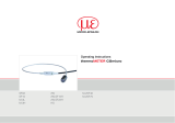
Ratio D = Distance From Device Front Edge to Measured Object/S = Spot Size
The size of the object to be measured and the optical resolution of the IR thermometer determine the maximum distance between sensor and object. To avoid
measuring errors, the measured object should completely fill the field of vision of the sensor's optical system. This means, the spot must always be at least as
large as or smaller than the measured object.
D 0 150 300 450 600 750 900 1050 1200 1350 1500 1800 2100 2400
S 20 19.5 19 18.5 18 17.5 17 16.5 16 20.5 25 34 43 52
Fig. 12 Example for model CTL-SF75
Additional D/S ratios are available in the operating instructions.
/