Troubleshooting Guide
DMP.COM
@DMPALARMS


INTRODUCTION .......................................... 1
About This Guide ����������������������������������������������������������������� 1
The Art of Troubleshooting ���������������������������������������������� 1
What’s the first thing to check? ������������������������������������� 1
TROUBLESHOOTING TOOLS ................... 2
Digital Multimeter ��������������������������������������������������������������� 2
DMP Tech APP and Dealer Admin �������������������������������� 2
System Analytics ����������������������������������������������������������������� 2
Support Center (Tech App Only) ��������������������������������� 2
THINGS TO KNOW .................................... 3
DMP Feature Codes ����������������������������������������������������������� 3
Common Voltages �������������������������������������������������������������� 3
BUILT-IN TOOLS......................................... 4
Onboard Diagnostics ���������������������������������������������������������4
Accessing the DIAGNOSTICS Menu ����������������������������4
MAXIMUM AUXILIARY
POWER OUTPUTS ..................................... 5
Wiring an Auxiliary Power Supply ������������������������������ 5
Resistor Values ��������������������������������������������������������������������� 6
How to Determine Resistor Value �������������������������������� 6
Output Information ������������������������������������������������������������ 7
Annunciator Outputs ��������������������������������������������������������� 7
Addressing Devices ������������������������������������������������������������ 8
Troubleshooting the 866 Style W
Notification Module ������������������������������������������������������������ 9
How the 866 Works ����������������������������������������������������������� 9
How to Troubleshoot An 866 �����������������������������������������9
CLEARING SYSTEM MESSAGES .............10
Phone Line 1 Trouble �������������������������������������������������������� 10
Phone Line 1 Trouble - XT30/XT50 Panels ������������� 10
Phone Line 1 Trouble - XR150/XR550 Panels �����������11
4-Wire Bus Trouble ������������������������������������������������������������12
Transmit Fail ������������������������������������������������������������������������� 12
System Trouble �������������������������������������������������������������������15
System Busy ������������������������������������������������������������������������� 15
Tamper Trouble (XR Panels only) �������������������������������� 17
Wireless Trouble �����������������������������������������������������������������17
Common Keypad Messages �������������������������������������������18
COMMON TROUBLESHOOTING .............19
Can’t Get into Local Programming �����������������������������19
Panel Won’t Arm �������������������������������������������������������������� 20
How an Area System Works ������������������������������������������21
Display Doesn’t Clear After an Alarm �����������������������22
Can’t Silence Bell/Siren ��������������������������������������������������23
Panel is Armed, Zones Do Not Trip ����������������������������23
Can’t Disarm������������������������������������������������������������������������24
Door Access Troubleshooting �������������������������������������� 24
Troubleshooting Using
the Transmitter Survey LED ������������������������������������������25
General Wireless Troubleshooting �����������������������������25
TABLE OF CONTENTS
XR150/550 DIAGNOSTICS MENU ......... 26
Test LX-Bus �������������������������������������������������������������������������� 26
ZONE FINDER ��������������������������������������������������������������������26
Zone State ���������������������������������������������������������������������������27
LX-Bus Status ���������������������������������������������������������������������27
X-Bus ��������������������������������������������������������������������������������������28
Mac Address������������������������������������������������������������������������28
Serial Number ��������������������������������������������������������������������� 28
Loader Version �������������������������������������������������������������������28
Current Flash ����������������������������������������������������������������������28
COMM Status ����������������������������������������������������������������������28
Cell Signal ����������������������������������������������������������������������������28
Activate Cell ������������������������������������������������������������������������28
PC Programming ���������������������������������������������������������������28
Test Z-Wave ������������������������������������������������������������������������� 28
Wi-Fi Signal �������������������������������������������������������������������������28
Stop ����������������������������������������������������������������������������������������28
NETWORK DIAGNOSTICS ...................... 29
CELL STATUS FAILURE
IDENTIFICATION CHART ........................30
FINDING AND HANDLING
INDUCTION .............................................. 32
Start with the basics first �����������������������������������������������32
Identifying induction (noise)
without an AC ground �����������������������������������������������������32
Troubleshooting Induction (noise) ����������������������������� 32
DMP SENDING CONTACT ID:
EVENT DEFINITIONS .............................. 33
Loop events & zone events �������������������������������������������33
Disarming/Arming & Late to Close ��������������������������� 34
Door access ������������������������������������������������������������������������ 34
Opening/Closing Schedule Changes ����������������������� 34
system messages without restoral ����������������������������� 35
system messages with restoral ������������������������������������ 35

iv Digital Monitoring Products, Inc. | Troubleshooting Guide

Digital Monitoring Products, Inc. | Troubleshooting Guide 1
INTRODUCTION
ABOUT THIS GUIDE
This guide was created to assist DMP Technical Support Technicians in helping DMP dealers troubleshoot and fixing any
problems they may have with DMP equipment� We now oer this guide to DMP dealers and technicians� Any text in this
guide within a paragraph or step that is CAPITALIZED indicates keypad display text�
Example: ENTER CODE:-
THE ART OF TROUBLESHOOTING
It is easy to overlook something simple when troubleshooting a system� Whatever your problem is, the cause is usually
something simple, so don’t skip the basics�
Perhaps something was overlooked in programming, or maybe something is physically incorrect, such as an incorrectly
placed panel-jumper, an unplugged transformer, or a harness on the wrong header�
When you’re troubleshooting at an installation site or on a service-call, your job is to get the equipment working as
quickly as possible�
When working with any manufacturer’s equipment, the key to troubleshooting is to know what questions to ask first�
For example, let’s say you have a ‘dead’ keypad� It has no display and does not respond when keys are pressed�
WHAT’S THE FIRST THING TO CHECK?
1
DC voltage at the keypad harness: Is the keypad getting power?
2
DC output on panel terminals 7 & 10: Is the panel supplying power?
3
Wire connections at panel terminals 7 & 10: Is the keypad connected to the panel correctly?
4
AC input on panel terminals 1 & 2: Is the panel getting AC power?
These are all correct troubleshooting steps for a ‘dead’ keypad� But the order in which these steps are taken can change
depending on the layout of your system�
If the keypad is in the same room as the panel, it may be easier to check terminals 7 & 10 for DC output first� If the
keypad is 1000 ft away, you may save yourself a trip back to the panel by checking the keypad’s wire harness for proper
DC voltage� It just depends�

2 Digital Monitoring Products, Inc. | Troubleshooting Guide
TROUBLESHOOTING TOOLS
DIGITAL MULTIMETER
A multimeter is definitely a must-have tool when troubleshooting an electronic device, such as an alarm panel� In fact, all
you need for basic troubleshooting is an inexpensive, basic digital multi-meter that can measure AC voltage, DC voltage,
Ohms ( W ) and continuity�
Try to keep a spare battery for your multimeter� When your meter’s battery is low, the meter may not give an accurate reading
which makes troubleshooting dicult due to misleading results�
DMP TECH APP AND DEALER ADMIN
The Tech APP (Automatic Panel Programming) is a mobile tool that allows you to add, edit, and view customers,
systems, and app users� You have the ability to quickly adjust system programming directly from the app, as well as
access full programming and reporting options� Programming can then be pushed to a system, allowing you to remotely
program customer’s systems� To use the Tech APP, you must have a valid account username and password given to you
by a Dealer Admin administrator�
SYSTEM ANALYTICS
Contains system information such as:
1
Customer—The customer’s name�
2
Account—The customer’s account number�
3
System Name—The name of the customer’s system�
4
Type—The system type, such as XR150, XT30, XTLplus, CellCom, etc�
5
Software Version—The current system firmware version�
6
Cell Signal Information—Information about cell signal communication� Thisapplies only to systems with an
active cellular module� For more information, refer to the appropriate DMP guides�
7
Retries—Information about communication retries� The information displayed depends on the system’s
connection type�
8
System and Battery Voltage—Information about system voltage and battery voltage�
SUPPORT CENTER (TECH APP ONLY)
1
Installation Guide—View the system’s installation guide�
2
Programming Guide—View the system’s programming guide�
3
Troubleshooting Tools—View door access, keypad, cellular, and network error messages�
4
DMP Guides—View all of DMP’s product guides on the DMP website�
5
Email Pics—Take a picture of an installation to send to someone who can help you�
6
Contact Technical Support—Contact DMP technical support�

Digital Monitoring Products, Inc. | Troubleshooting Guide 3
THINGS TO KNOW
DMP FEATURE CODES
All XR Series panels use a number to access certain features� Some of these features include the programmer menu,
diagnostic menu, and the walk-test function�
Most of these codes have a word-equivalent that can be spelled out using the keys on the keypad:
DMP FEATURE CODE MENU ITEMS
DMP FEATURE CODE SPELLING
Programmer Menu 6653 PROG
Diagnostics Menu 2313 DIAG
Walk Test Menu 8144 WALK
Keypad Options 3577 INST
Communication Test Menu 984
COMMON VOLTAGES
These operating voltages are the same across the entire XT30/50 and XR150/550 product-line:
1
AC input (terminals 1 and 2) – 17�3 VAC (We include 16�5 VAC Power Supplies�)
2
Charging circuit output (terminals 3 and 4) – 13�9 VDC
3
Auxiliary power output (terminals 7 and 10) – 13�8 VDC
4
Panel data receive output YELLOW (terminals 8 and 10) – approx� 4�5 VDC
5
Panel data transmit output GREEN (terminals 9 and 10) – approx� – 3�5 VDC
OPERATIONAL PARAMETERS FOR XR PANEL ZONES 1 - 8 & XT PANEL ZONES 1 - 9
ZONE CONDITION RESISTANCE ON ZONE VOLTAGE ON + TERMINAL
OPEN More than 1300 Ohms Above 2�0 VDC
NORMAL 600 - 1300 Ohms 1�2 - 2�0 VDC
SHORT Less than 600 Ohms Below 1�2 VDC
The following chart shows the operational parameters for XR Panel zones 1 - 8 and XT Panel zones 1 - 9 when 2�2K resistors
are enabled on v193 or higher firmware�
ZONE VOLTAGES USING 2.2K Ω RESISTORS
STATE VOLTAGE
SHORT 0 - 2�1 VDC
NORMAL 2�2 - 2�9 VDC
OPEN ≥ 3 VDC

4 Digital Monitoring Products, Inc. | Troubleshooting Guide
BUILT-IN TOOLS
ONBOARD DIAGNOSTICS
Select DMP systems have several built-in Diagnostic features that are accessible from a keypad and can assist technicians
when troubleshooting a system� These Diagnostic functions allow you to test the communication integrity of the LX-
Bus™, identify the state of individual zones, test communication, and also display the present electrical state of any zone�
The Diagnostics menu options include:
PANEL DIAGNOSTICS MENU
MENU OPTIONS XR SERIES XT30/50 XTL+
Diagnostics
Test LX-Bus
Zone Finder
Zone State
LX-Bus Status
X-Bus
MAC Address
Serial Number
Loader Version
Current Flash
Communication Status
Cellular Status
Cellular Signal Strength
Activate Cell*
Email Status
Panel Settings
PC Programming
Test Z-Wave
Initialize Z-Wave
Wi-Fi Signal
Stop
Note: *Only needed for 263C and 265C Cell Modems
ACCESSING THE DIAGNOSTICS MENU
1
Reset the panel using the RESET jumper unless it has been less than 30 minutes since either:
A
You were in Programming,
B
You were in the Diagnostics menu,
C
You powered up the panel, or
D
You last reset the panel�
2
Enter 2313 for an XT Series keypad and 2313 + CMD for an XR Series keypad� (‘2313’ spells DIAG�)
3
The keypad displays DIAGNOSTICS� Press the CMD key to move forward through the Diagnostics menu�

Digital Monitoring Products, Inc. | Troubleshooting Guide 5
MAXIMUM AUXILIARY POWER OUTPUTS
All DMP panels provide 12 VDC of auxiliary power for system accessories, such as keypads, zone expanders, supervision
modules, and intrusion detectors�
XR150 and XR550: 1500 mA (1�5 A)
XT30 and XT50: 500 mA (0�5 A)
Each device consumes a portion of the panel’s available auxiliary power� When the auxiliary power demand is too great,
the panel shuts down the auxiliary power circuit� That means that anything powered by the panel is now dead� To take
some of the load o of the panel, an auxiliary power supply can be used�
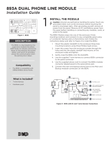
WIRING AN AUXILIARY POWER SUPPLY
The Sensor Reset Output can be used to reset 2-wire smoke detectors (wired to Model 715 zone expanders) by dropping
power to the bus for five seconds when a Sensor Reset is performed�
If that isn’t necessary, then the positive voltage may go directly from the power supply to the devices on the bus�
Note: Always be sure that the negative side of the auxiliary power supply is connected to the black wire of
the bus you are using it on�

6 Digital Monitoring Products, Inc. | Troubleshooting Guide
RESISTOR VALUES
DMP panels use resistors of dierent values to control dierent system voltages, such as zone voltages and bell
supervision voltages�
RESISTOR VALUES USED WITH DMP EQUIPMENT
1,000 Ohm Panel zones 1-8, 711 & 714 zone expanders, DMP keypad zones
3,300 Ohm Panel zone 9 (XT30/XT50), panel zone 9 & 10 (XR), all Model 715 zone expanders
10,000 Ohm 866 & 867 Bell Supervision
470k Ohm 1103 & 1114 Wireless Transmitters
2M Ohm 1115 with External Water Probe
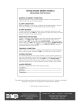
HOW TO DETERMINE RESISTOR VALUE
Resistor values can be determined by the color code on the resistor� With the Gold or Silver band positioned to the right,
look at the other color-bands from left to right�
The first color-band on the left determines the first number of the resistor’s value and the second color-band determines
the second number of the resistor’s value�
The third color-band tells us how many zeros to put behind the first two numbers�
The last band (either Gold or Silver) represents the resistor’s tolerance, meaning that the actual resistance can vary
above or below the value indicated by the color code�
Note: The resistor shown above has: Brown (= 1), Black (= 0), Red (= 2), and Gold (± 5%)� So this resistor
has a value of 1,000 Ohms�

Digital Monitoring Products, Inc. | Troubleshooting Guide 7
OUTPUT INFORMATION
1
Dry Contact Relays DMP Part #305�
2
Single pole, Double throw�
3
Rated at 1 Amp @ 30 VDC resistive�
4
May be activated by any of the following:
Zone Condition (Open/Short) Output Schedule Manually from User Menu
Communication Fail Armed Area Annunciation Fire Alarm / Fire Trouble
Other System Conditions
ANNUNCIATOR OUTPUTS
Available on XT30/XT50 Series, XR150/XR550 Series, CellComLTE-V, iComSL, Dualcom, and 716 Output Expander�
1
Switch to GROUND when activated�
2
Do not provide voltage�
3
50mA resistive�
4
Activated by same conditions as Model 305 Dry Contact Relay and Voltage outputs�
PANEL OUTPUT NUMBER
XR150/XR550 Series 3-6
XT30/XT50 Series 1-4

8 Digital Monitoring Products, Inc. | Troubleshooting Guide
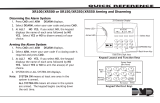
ADDRESSING DEVICES
Setting Address on 7000 Series keypads
1
Press and hold the CMD and Back Arrow keys until SET BRIGHTNESS appears on display�
2
Enter 3577 (INST) + CMD�
3
Press key under KPD OPT (Keypad Options)�
4
Keypad displays CURRENT KEYPAD ADDRESS: xx (xx = address 01-16)�
5
Press any top row select key�
6
Enter desired address� (Do not enter leading zeroes�) Press CMD to scroll to next option�
7
KEYPAD MODE: SUP UNSUP: To choose Supervised or Unsupervised operation, press select key under SUP
or UNSUP� Press CMD� (Keypads should be left Supervised unless specifically needing to be Unsupervised�)
8
DEFAULT KEYPAD MSG: Press select key, enter message to be displayed on top row of display, and then
press CMD�
9
ARM PANIC KEYS: PN EM FI: Press select keys below each to enable� When enabled, each will appear as
*PN *EM *FI (report as Zones: PN=19, EM=29, FI=39)� Press CMD�
10
ACTIVATE ZONE 2 BYPASS: NO -: Used with 7073 and 7873 keypads for Soft Shunt function� Press CMD�
11
RELOCK ON ZONE 2 CHANGE: NO -: Used with above keypads for relocking a door when the zone returns
to a normal state, instead of wating for the strike time to expire�
12
ACTIVATE ZONE 3 REX: NO –: Also used with above keypads for REX function� Press CMD�
13
NO OF USER CODE DIGITS: 5 –: Press top row key, press 4, and then press CMD for Home/Away or other
systems that require 4 digit codes� Press CMD�
14
ALL? NO YES DELAY: 2 –: This option is for use in an Area Mode system� When arming, ALL? YES NO is
displayed on the keypad� When NO or YES is not selected before this delay (1 to 9 seconds) expires, the
keypad automatically selects YES� Enter zero to disable this feature� Press the CMD key�
15
CARD OPTIONS DMP -: Sets the card format used by the reader in the keypad� Press select key for custom
option�
16
REQUIRE SITE CODE: NO -: Determines if an access credential’s site code will be required�
17
NO COMM WITH PNL OFF -: Defines the state of the door if the keypad loses communication with the
panel� Press select key for more options�
18
SYSTEM OPTIONS: AREA -: (Graphic touchscreen keypads only) Set to the same system type that is set in
System Options in the panel’s programming menu for proper shield operation�
19
DEALER LOGO ADD DELETE -: (Graphic touchscreen keypads only) Load or update the logo displayed on
the main screen�
20
DEALER INFO ADD DELETE -: (Graphic touchscreen keypads only) Load or update the contact information
stored in the keypad�
21
KPD OPT KPD DIAG STOP –: Press select key under STOP�

Digital Monitoring Products, Inc. | Troubleshooting Guide 9
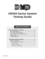
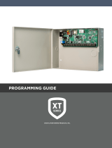
TROUBLESHOOTING THE 866 STYLE W NOTIFICATION MODULE
The 866 uses the panel’s bell circuit to switch power from an external power source to sirens and other notification
devices� It also supervises the connection to the external power source� The most important thing to know with the 866
is which wires connect to the panel versus which wires connect to the power source�
HOW THE 866 WORKS
1 & 2 power the 866 module� The positive trigger on terminal 3 tells 2 & 4 to send voltage to 5 & 6�
HOW TO TROUBLESHOOT AN 866
1
Metering 1 & 2 should show +12V (or +24V if using a 24V power supply)�
2
If no voltage between 1 & 2, make sure the ground and power are coming from the same source (panel or
power supply)�
3
Metering 2 & 3 should show approximately 0 to 1�2V when normal�
4
Metering 2 & 3 should show +12V when tripped�
5
If using Horn Strobes, steady voltage on terminal 3 is required�
6
If they say the 866 should be tripping, they must have +12V on 2&3 to be triggering it�
7
Metering 2 & 4 should show +12V (or +24V)�
8
If power is coming from the panel bell, you will have 0-1�2V until the bell trips�
9
If no voltage on 2 & 4, you won’t have any power to power the bell output� Make sure the ground and
power are coming from the same panel or power supply�
10
Metering 5 & 6 should show negative volts while the 866 is normal (-6V or -12V) then +12V (or +24V)
when triggered�
11
If the bell isn’t tripping, strap out 5 & 6 with a 10K resistor and meter terminals 5 & 6 while tripped�
12
If you are experiencing a delay when sounding, make sure the bell silence switch is normal and a 10K
resistor is installed on terminals 5 & 6�
13
Metering 7 & 8 for continuity should show continuity while normal� If there is no 10K resistor on 5 & 6, this
contact will show open� Remember, this is a contact, not a zone�
14
If the Normally Closed contact on 7 & 8 is open make sure the silence switch is normal and that there is a
10K on 5 & 6�

10 Digital Monitoring Products, Inc. | Troubleshooting Guide
CLEARING SYSTEM MESSAGES
Here are some common system messages that may display on a keypad� A brief description of what the message means
and some basic troubleshooting tips are listed under each system message heading�
PHONE LINE 1 TROUBLE
PHONE LINE 1 TRBL or PHONE LINE 2 TRBL means that the panel detects a problem with the telephone line� Because
of hardware dierences between DMP residential models and DMP commercial models, PHONE LINE 1 TRBL or PHONE
LINE 2 TRBL can mean a couple of things�
RJ supervision for DMP XR200 panels is achieved by placing a jumper wire across pins 2 & 7 of the RJ-31X�
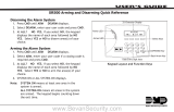
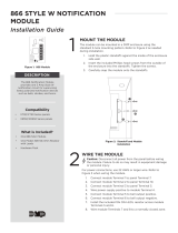
PHONE LINE 1 TROUBLE - XT30/XT50 PANELS
Connect the RJ SUP header to an available zone on the panel� When the telephone cable is removed, the keypad
displays zone trouble along with the zone name and produces a steady tone�
To correct this condition:
1
Check the RJ cable for continuity� There may be a broken wire� If so, replace the RJ cable with DMP Model
356-2�
2
Make sure that RJ-31X pin-out is correct—RJ-31X pin-out—as shown below�

Digital Monitoring Products, Inc. | Troubleshooting Guide 11
PHONE LINE 1 TROUBLE - XR150/XR550 PANELS
XR Series panels monitor telephone line voltage� When the voltage falls below 3 VDC, the panel generates a PHONE LINE 1
TRBL�
If you are using a Model 893-A Dual Phone Line Module and the voltage falls below 3 VDC, the panel generates a PHONE
LINE 1 TRBL or PHONE LINE 2 TRBL, depending on which line has a problem� Here are some things to check:
CHECK PHONE LINE VOLTAGE
1
Set your multi-meter to DC voltage�
2
With the panel still connected to the RJ-31X, place meter-leads on pins 4 & 5� If properly wired for line seizure,
this should be your incoming dial tone�
3
Check voltage� When the panel is ON-HOOK (not dialing) this voltage should read somewhere between 45 and
55 VDC�
4
Make the panel go OFF-HOOK (an easy way to do this is to remove and replace the tamper jumper) and read
the phone line voltage again�
Note: If the phone line voltage drops below 3 VDC, the problem lies with the phone line� If it does not drop
below 3 VDC, try BYPASSING THE 893A� To do this:
1
Place a jumper wire across pins 2 & 7 of the RJ-31�
2
Disconnect the short RJ cable (between panel J3 and 893A) from the panel�
3
Unplug RJ cable from 893A’s MAIN (Remove BACKUP for PH LINE 2 TRBL), plug into panel’s dialer
connection�
4
Wait up to two minutes for PH LINE TRBL to clear�
DOES PH LINE TRBL CLEAR?
YES - Replace 893A Module� Be sure to power down the panel first�
NO - Enter PROGRAMMING and initialize EVENTS� This should clear the display� Wait at least two minutes after
initializing EVENTS to make sure that the PH LINE TRBL does not return�
Note: Initializing EVENTS erases ALL EVENTS in the Event Buer�

12 Digital Monitoring Products, Inc. | Troubleshooting Guide
4-WIRE BUS TROUBLE
When the keypad displays 4-WIRE BUS TRBL it means that the panel has a problem communicating with the keypad
bus devices� 4-WIRE BUS TRBL is not an indication of LX-Bus issues� More specifically, when the panel polls the keypad
bus devices, they aren’t able to respond�
4-WIRE BUS TRBL only displays for the following reasons:
1
All keypad bus devices set to Unsupervised:
Make sure at least one keypad bus device is set as Supervised�
2
Multiple keypad bus devices set to same Supervised address:
Make sure that all keypad bus devices are addressed correctly (all devices sharing an address*
must be set as UNSUPERVISED)�
3
Low voltage or no voltage on the panel’s Yellow (receive) wire (terminal 8):
Check data voltage (DC) across terminals 8 & 10 at the panel and at the device� If the voltage is low
or open, remove the wires from terminals 7 - 10 and check voltage again�
If still low or open, reset the panel using the J16 jumper and check the voltage again� If voltage is
still low or open, remove all wiring (except AC power) and check again� This last step is taken to
make sure that transient voltage isn’t being fed into the panel from the field wiring�
Note: Multiple UNSUPERVISED devices may share the same address, as long as:
All devices using the same address are set for UNSUPERVISED operation,
None of the devices using the same address are being used for zone expansion, and
There is sucient auxiliary power available to operate the devices� Auxiliary power may be
provided by the panel or an auxiliary power supply or both�
TRANSMIT FAIL
When the keypad displays TRANSMIT FAIL it means that the panel made 10 attempts to communicate with the receiver,
but was unsuccessful�
After the ten attempts have failed, the panel tries once every hour to send a TRANSMIT FAIL message to the receiver�
The keypad only displays TRANSMIT FAIL when a user disarms the system or when an unsuccessful SYSTEM TEST has
been initiated from the User Menu�
WHAT TO DO
1
Arm the system� Let the Exit Delay timer count all the way down, and then disarm the system�
If communication to the receiver has been restored (i�e�- the panel successfully communicated the
TRANSMIT FAIL or any other signal), this should clear the display�
2
Try to send a test-signal�

Digital Monitoring Products, Inc. | Troubleshooting Guide 13
XR SERIES PANELS
To test cellular or network communication:
1
Enter the diagnostics menu (DIAG) and press CMD until COMM STATUS displays�
2
Press any select key and enter the number of the path to be tested�
To test phone line communication:
1
Enter the User Menu�
2
Press the CMD key until the display reads SYSTEM TEST?�
3
Press any Select key� Watch the keypad display� When it shows ATTEMPT NO: 1, the panel dials the first
Phone Number programmed in RECEIVER 1 PROG of Communication�
4
When the panel successfully communicates to the receiver, the keypad display changes to TRANSMIT
OKAY� The panel attempts to send this test-signal up to 10 times�
XT SERIES PANELS, ICOM, CELLCOM, AND DUALCOM
To test cellular communication:
1
Enter the diagnostics menu (DIAG) and press CMD until CELL STATUS displays�
2
Press any select key to start the test�
To test a network connection:
1
Enter 984 + CMD and select NET�
To test phone line communication:
1
Enter the User Menu; press the CMD key until the display reads SYSTEM TEST?�
2
Press any Select key� Watch the keypad display� When it shows ATTEMPT NO: 1, the panel dials the first
Phone Number programmed in RECEIVER 1 PROG of Communication�
3
When the panel successfully communicates to the receiver, the keypad display changes to TRANSMIT
OKAY� The panel attempts to send this test-signal up to 10 times�
Verify the phone numbers by calling them from a butt-set at the RJ-31 connected to the panel’s
dialer connection� Does a receiver answer? Are you sure it isn’t a fax machine?
If NO-, find the correct phone number and program it into the panel�
If YES-, verify with central station that it is the correct receiver for the panel’s programmed
communication format�
DD = DMP SCS-1R
NET = DMP SCS-1R or SCS-VR receiver
CID = DMP SCS-1R or any receiver that accepts Ademco Contact ID format
CELL = DMP SCS-1R or SCS-VR receiver

14 Digital Monitoring Products, Inc. | Troubleshooting Guide
4
Are the phone numbers in communication entered correctly?
Make sure that the panel is dialing the correct phone number�
Make sure that the panel doesn’t need to dial a ‘9’ or other digit to get an outside line�
Be sure to include any pauses the panel needs�
Enter a P before the phone number for a three-second pause in the dialing sequence�
Enter a D to make the panel wait for dial tone before dialing�
5
Is panel wired for proper line seizure?
If a phone line is shared with house-phones, fax machine, or other equipment, proper line seizure is
a must� If the panel does not have line seizure and someone or something else is using the phone
line, the panel can’t use the line�
TRANSMIT TROUBLE
When the keypad displays TRANSMIT TRBL it means that the panel had to make at least three attempts to communicate
to the receiver� The way to clear Transmit Trouble is to get the panel to communicate on the first or second attempt�
XR SERIES PANELS:
1
To test cellular or network communication, enter the diagnostics menu (DIAG) and press CMD until
COMMSTATUS displays� Press any select key and enter the number of the path to be tested�
2
To test phone line communication, enter the User Menu; press the CMD key until the display reads
SYSTEMTEST?�
3
Press any Select key� Watch the keypad display� When it shows ATTEMPT NO: 1, the panel dials the first
Phone Number programmed in RECEIVER 1 PROG of Communication� When the panel successfully
communicates to the receiver, the keypad display changes to [TRANSMIT OKAY]� The panel attempts to
send this test-signal up to 10 times�
XT SERIES PANELS, ICOM, CELLCOM, AND DUALCOM:
1
To test cellular communication, enter the diagnostics menu (DIAG) and press CMD until CELL STATUS
displays� Press any select key to start the test�
2
To test a network connection, enter 984 + CMD and select NET�
3
To test phone line communication, enter the User Menu� Press the CMD key until the display reads
SYSTEMTEST?� Press any Select key� Watch the keypad display� When it shows ATTEMPT NO: 1, the panel
dials the first Phone Number programmed in RECEIVER 1 PROG of Communication� When the panel
successfully communicates to the receiver, the keypad display changes to [TRANSMIT OKAY]� The panel
attempts to send this test-signal up to 10 times�

Digital Monitoring Products, Inc. | Troubleshooting Guide 15
If the panel is not communicating to the receiver within two attempts:
1
Check RJ-31X wiring for proper line seizure�
If phone line is shared with house-phones, fax machine or other equipment, proper line seizure is
a must� If the panel does not have line seizure and someone or something else is using the phone
line, the panel can’t use the line�
2
Use a butt-set connected to the panel’s RJ-31X to call the receiver phone number as programmed in
COMMUNICATION > RECEIVER 1 PROG� Is it a working phone number? If not, program the panel with the
correct phone number�
3
Send another System Test to the receiver to verify that the communication is taking place within two
attempts�
SYSTEM TROUBLE
1
Low or no (open) voltage on the Green wire of the keypad bus�
2
Reset jumper shorting both pins of the RESET header�
3
Processor failure�
SYSTEM BUSY
SYSTEM BUSY can mean that the panel is busy with other communication� Try to reset the panel� If the display does not
clear, SYSTEM BUSY can also mean that the panel’s microprocessor is damaged�
A few things to check:
1
Make sure the RESET header is not shorted�
2
Make sure the green wire (terminal 9) is not shorted to the ground or any other wire�
If that doesn’t clear the display, try this:
1
Check DC voltage across terminals 8 & 10� Check DC voltage across terminals 9 & 10�
If both measure at 5 VDC, reset the panel and check the voltages again�
2
If both voltages still measure at 5 VDC, remove panel ground and remove all wiring from terminals 7, 8, 9, &
10�
3
Reset the panel� Check data voltages�
If both voltages still measure at 5 VDC, replace the panel�
If voltages are correct now, begin replacing terminal 7, 8, 9, & 10 wiring� Be sure to check data
voltages after each wire is replaced�
By checking the voltages in this manner, you should be able to see when the voltage problem
occurs� When it does, the wire you just replaced is most likely to be the cause of the problem or a
device connected to that wire�

16 Digital Monitoring Products, Inc. | Troubleshooting Guide
NON-POLLED ADDRESS
When the keypad displays [NON POLLED ADDR] it means that the keypad’s address is not programmed in device setup�
To correct this condition:
If only one keypad is connected to the system and the address is set to something other than ADDRESS 1, this is almost
sure to be the problem�
1
Set the keypad’s address to 1 and exit Keypad Installer Options� You should be up and running now�
If there are multiple devices on the keypad bus:
1
Check the keypad’s address in the Keypad Installer Options� Is it correct?
If not, change it� Exit Installer Options� Does the keypad work now? If not���
2
Enter 6653 (PROG) from a keypad that is working correctly� Check DEVICE SETUP programming�
Be sure that the address is set to KPD (set to FIRE for Model 630F keypads) and exit Programming�
Now check the keypad in question� It should work correctly�
BATTERY TROUBLE
In a normal condition, the panel tests the backup battery every 3 minutes by performing a load-test on the battery�
This test lasts for 5 seconds� If the battery voltage falls below 11�9 VDC during this test, the panel generates a
BATTERY-TRBL� This signal is also sent to the central station� In the trouble condition, panel re-tests the battery every 2
minutes� When the battery’s DC voltage rises to 12�6 VDC, the BATTERY -TRBL clears from the display and the restoral is
sent to the central station�
If the battery has been replaced and the trouble condition is still present, try getting into and out of Programming� This
re-starts the 3-minute load-test timer� This usually will clear the BATTERY -TRBL� If not, try these steps:
1
Remove the AC wiring from terminals 1 & 2, so that only the battery powers the panel�
2
Set your meter to DC voltage and place the leads on terminals 3 & 4� Is the voltage above 11�9 VDC?
NO – Then the panel sees the new battery in a trouble condition� You can wait for the new battery
to charge to 12�6 VDC OR you can check the charging circuit…
YES – Replace AC wiring on terminals 1 & 2, remove battery leads from the battery� Check DC
voltage on terminals 3 & 4� You should see about 13�8 VDC (14�2 VDC max�) when the batteryis
disconnected�
If you see less than 13�8 VDC, the panel’s charging circuit may be damaged, in which case the panel will have to be
repaired� Any time the battery voltage falls below 10�2 VDC, the panel disconnects the battery� This is to prevent deep-
discharge damage to the battery�
Page is loading ...
Page is loading ...
Page is loading ...
Page is loading ...
Page is loading ...
Page is loading ...
Page is loading ...
Page is loading ...
Page is loading ...
Page is loading ...
Page is loading ...
Page is loading ...
Page is loading ...
Page is loading ...
Page is loading ...
Page is loading ...
Page is loading ...
Page is loading ...
Page is loading ...
Page is loading ...
/