Assa Abloy PADDE Series Installation guide
- Type
- Installation guide
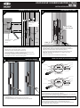
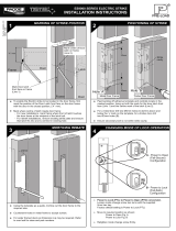
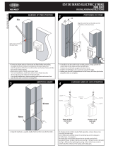
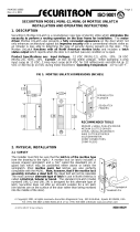
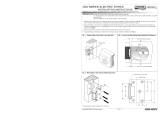
Assa Abloy PADDE Series is a range of electric strikes designed for use in a variety of applications, including access control, door automation, and security.
The PADDE Series strikes are available in a variety of sizes and configurations to suit different door types and requirements. They are also compatible with a wide range of access control systems and door automation devices.
Some of the key features of the PADDE Series strikes include:
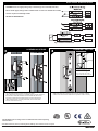
- Fail-safe or fail-secure operation
- Adjustable latching speed
- Built-in LED indicator
- Tamper switch
- Anti-pry design
The PADDE Series strikes are easy to install and can be used in both new and existing doors. They are also backed by a comprehensive warranty.
Assa Abloy PADDE Series is a range of electric strikes designed for use in a variety of applications, including access control, door automation, and security.
The PADDE Series strikes are available in a variety of sizes and configurations to suit different door types and requirements. They are also compatible with a wide range of access control systems and door automation devices.
Some of the key features of the PADDE Series strikes include:
- Fail-safe or fail-secure operation
- Adjustable latching speed
- Built-in LED indicator
- Tamper switch
- Anti-pry design
The PADDE Series strikes are easy to install and can be used in both new and existing doors. They are also backed by a comprehensive warranty.


-
 1
1
-
 2
2


Assa Abloy PADDE Series Installation guide
- Type
- Installation guide
Assa Abloy PADDE Series is a range of electric strikes designed for use in a variety of applications, including access control, door automation, and security.
The PADDE Series strikes are available in a variety of sizes and configurations to suit different door types and requirements. They are also compatible with a wide range of access control systems and door automation devices.
Some of the key features of the PADDE Series strikes include:
- Fail-safe or fail-secure operation
- Adjustable latching speed
- Built-in LED indicator
- Tamper switch
- Anti-pry design
The PADDE Series strikes are easy to install and can be used in both new and existing doors. They are also backed by a comprehensive warranty.
Ask a question and I''ll find the answer in the document
Finding information in a document is now easier with AI
Related papers
-
Assa Abloy ES100 Series Installation guide
-
-
-
Assa Abloy 75 User manual
-
-
Assa Abloy Sargent 8200 Installation Instructions Manual
-
-
-
-
Assa Abloy Lockwood 3579 Series Mounting instructions
Other documents
-
 LOCKWOOD (ASSA ABLOY) ES9000 Technical Manual
-
LOCKWOOD (ASSA ABLOY) ES201 Technical Manual
-
ENTRO A0200SSSM User manual
-
ERA LAL0032 Operating instructions
-
-
 Lockwood ES150 Series Installation guide
-
 LOCKWOOD (ASSA ABLOY) ES8000-1 Technical Manual
-
 LOCKWOOD (ASSA ABLOY) ES6000M User manual
-
 Assa Door Lock User manual
-
 LOCKWOOD (ASSA ABLOY) ES150-1 Technical Manual


