2
A8131E 11/17
BHL Trim
Installation Instructions
8200 Mortise Lock
Copyright © 2017, Sargent Manufacturing Company, an ASSA ABLOY Group
company. All rights reserved. Reproduction in whole or in part without the express
written permission of Sargent Manufacturing Company is prohibited.
1-800-727-5477 • www.sargentlock.com
1
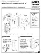
Mortise Lock Handing Instructions
To rotate locking piece:
1. Position lockbody with red surface of locking piece
visible.
2. Insert blade type screwdriver into locking piece slot
to rotate locking piece.
3. Push locking piece toward back of lockbody and
rotate 180° until RED surface shows on opposite
side.
For 04, 06, 13 and 31 Functions:
(a) Remove green catch screw.
(b) Rotate hub to 45° position.
(c) Rotate locking piece for required hand.
(d) Face red surface to locked side of door.
(e) Rotate hub to original 45° position (as
shown on lockcase).
(f) Reinstall green catch screw.
NOTE:
RED SURFACE OF LOCKING PIECE MUST FACE
SECURE SIDE OF DOOR.
Red color indicates locked
side of door or hold back
side (91 and 92 Functions)
Locking
piece
slot
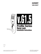
To change hand of latch:
1. Insert screwdriver blade into the spade shaped slot.
2. Rotate screwdriver 90° to push latch out until back
of latch clears lock front. Rotate latch 180°. Latch
will re-enter lockbody.
NOTE:
BEVELED SURFACE OF LATCH MUST FACE
STRIKE. DEADLATCH IS SELF ADJUSTING.
NOTE:
LATCH CANNOT BE UNSCREWED.
Spade Shaped Slot
k Front
Latch