Page is loading ...

English
Before installing and operating the camera, please read this user’s manual carefully.
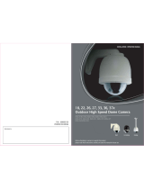
SPD-3750T/3750/3350
37X/33X High Resolution WDR PTZ Dome Camera
37x/33x Ultra-Low Light & WDR SPEED DOME CAMERA
SPD-3750T/3750/3350
User’s Manual

The lightning flash with an arrowhead symbol, within an equilateral triangle is
intended to alert the user to the presence of uninsulated “dangerous voltage”
within the product's enclosure that may be of sufficient magnitude to constitute
a risk of electric shock to persons.
The exclamation point within an equilateral triangle is intended to alert the user
to the presence of important operating and maintenance (servicing) instructions
in the literature accompanying the appliance.
This installation should be made by a qualified service person and
should conform to all local codes.
INFORMATION - This equipment has been tested and found to comply with
limits for a Class A digital device, pursuant to part 15 of the FCC Rules. These
limits are designed to provide reasonable protection against harmful
interference when the equipment is operated in a commercial environment.
This equipment generates, uses, and can radiate radio frequency energy and,
if not installed and used in accordance with the instruction manual, may
cause harmful interference to radio communications.
Operation of this equipment in a residential area is likely to cause harmful
interference in which case the user will be required to correct the interference
at his own expense.
WARNING
- CHANGES OR MODIFICATIONS NOT EXPRESSLY APPROVED BY THE
MANUFACTURER COULD VOID THE USER'S AUTHORITY TO OPERATE
THE EQUIPMENT.
- TO REDUCE THE RISK OF FIRE OR ELECTRIC SHOCK, DO NOT EXPOSE
THIS PRODUCT TO RAIN OR MOISTURE.
CAUTION : To prevent electric shock and risk of fire hazards:
- The installation for this apparatus should be by a qualified service person
and should conform to all local codes.
- Do NOT use power sources other than Class 2 power source.
- Carefully push the unlock buttons to prevent injury due to falling of this
apparatus.

SPEED DOME CAMERA User’s Manual
4
SPEED DOME CAMERA User’s Manual
5
Contents
•
Features
………………………………………………………………………… 6
•
Cautions for Using Auto Track (SPD-3750T)
………………………… 7
•
Warnings & Cautions
……………………………………………………… 9
•
Components and Accessories
…………………………………………… 12
•
Component Names and Functions
……………………………………… 13
•
Installing Your Camera
……………………………………………………… 15
■
Speed Dome Camara and Appliances Wiring Diagram
……… 15
■
Communication DIP Switch Settings (SW2)
……………………… 17
▶ Protocol Settings
…………………………………………………………………… 17
▶ Baud Rate Settings
………………………………………………………………… 18
▶ Communication Method Settings
……………………………………………… 18
▶ Communication Response Settings
…………………………………………… 18
▶ Termination Settings
……………………………………………………………… 18
▶ Camera Backup Settings
………………………………………………………… 19
■
Camera ID DIP Switch Settings (SW1)
…………………………… 19
▶ Camera ID Chart
…………………………………………………………………… 20
■
On-Ceiling Mount Type Installation Example
…………………… 29
•
Interface Symbols
…………………………………………………………… 32
•
Operating Your Camera
…………………………………………………… 33
•
Functional Description
……………………………………………………… 37
■
Camera Setting
…………………………………………………………… 37
▶ Focus and Zoom
…………………………………………………………………… 37
▶ White Balance
……………………………………………………………………… 39
▶ Exposure
……………………………………………………………………………… 40
▶ Backlight
……………………………………………………………………………… 4 1
▶ AGC
…………………………………………………………………………………… 45
▶ SSNR(Samsung Super Noise Reduction)
…………………………………… 46
▶ Day & Night
………………………………………………………………………… 47
▶ Others
………………………………………………………………………………… 48
■
Sequence Setting
………………………………………………………… 49
▶ Power On Resume & MD Dwell Time
………………………………………… 49
▶ Preset
………………………………………………………………………………… 50
▶ Swing SEQ
…………………………………………………………………………… 54
▶ Group SEQ
…………………………………………………………………………… 55
▶ Tour SEQ
……………………………………………………………………………… 56
▶ PTZ Trace
…………………………………………………………………………… 57
▶ Auto Run
……………………………………………………………………………… 58
■
P/T Setting
………………………………………………………………… 59
▶ Pan/Tilt Limit
………………………………………………………………………… 59
▶ Area Setting
………………………………………………………………………… 60
▶ Area Masking
……………………………………………………………………… 6 1
▶ Prop. P/T
……………………………………………………………………………… 62
▶ Digital Flip
…………………………………………………………………………… 63
▶ Image Hold
…………………………………………………………………………… 64
▶ Auto Track1
………………………………………………………………………… 65
▶ Auto Track2
………………………………………………………………………… 67
•
OSD Setting
…………………………………………………………………… 69
•
Alarm Setting
………………………………………………………………… 70
•
Initialization Setting
………………………………………………………… 74
•
Status Check
…………………………………………………………………… 76
•
Product Specifications
……………………………………………………… 77

SPEED DOME CAMERA User’s Manual
6
SPEED DOME CAMERA User’s Manual
7
Versatile Protocol Processing
This camera supports a total of 8 types of communication
protocols: Samsung Techwin, Pelco-D, Pelco-P, Samsung
Electronics, Panasonic, Honeywell, AD and Vicon.
Area Masking
If a monitoring location includes a highly private area,
the area can be selectively masked on the screen.
OSD (On Screen Display)
The camera IDs, camera preset numbers, preset names,
area names, and camera operation status are displayed
on the monitor, allowing set up of various camera
functions through the OSD menu screen.
Preset Position Saving and Loading
Up to 255 preset positions can be set. Using this
function saves and brings up the camera feed of a
selected monitoring location.
Camera Backup
This is to back up the camera’s sequence information
and presets. This is useful when the camera or its
install base are damaged or malfunctions occur.
Day & Night
With its daytime & nighttime switch and Sens-Up
functions based on the ICR (Infrared Cut filter Removal)
method, the camera provides high quality pictures
regardless of whether it is day or night.
* Sens-Up increases the CCD sensitivity by electrically
extending the camera’s exposure time.
* Day & Night enables you to select between color and
B/W modes depending on the lighting conditions.
Digital Flip
The Digital Flip function is useful to monitor moving
objects or people passing directly under the camera.
When an object or a person passes directly under the
camera, its tilt monitor follows the object or person over
100 degrees to the other side of the tilt area without
panning. The screen inversion starting to occur at 100
degrees or higher is digitally adjusted.
Smart P/T
The Smart P/T function automatically adjusts the
control speed of the Pan and Tilt functions according to
the current zoom power. It is useful to adjust the
functions manually for detailed controls when
monitoring a high-powered zoom.
Wide Range Auto Security
Functions
- Auto Tracking(SPD-3750T Only) : A moving object or a
person can be tracked and recorded automatically by
the camera with its Pan, Tilt, and Zoom functions.
- Multiple Preset Function Saving : Up to 13 camera
image properities can be saved individually to provide
high quality pictures.
- Image Holding : When moving between presets in Group
and Tour functions, using this Preset Freeze function
holds the image status and helps the screen observer
relieve visual fatigue.
- PIZ Trace : Patterns operated with the joystick can be
saved and replayed by users.
- Swing : Using the Swing function commands the
camera to move between 2 selected locations,
monitoring the route.
- Group Search : Maximum 255 Preset positions are
toured in order.
- Tour Search : Maximum 6 Group Search functions are
toured in order.
A/F 37x/33x Optical Zoom
The built-in 37x(SPD-3750T/3750)/33x(SPD-3350) optical
zoom lens with auto-focus is combined with a 12x digital
zoom, providing a maximum of 444x/396x zoom.
Features
Cautions for Using Auto Track (SPD-3750T)
The following cautions are for the Auto Track function built-in with the SPD-3750T; The SPD-
3750/3350 do not have Auto Track.
To use Auto Track to its full potential, please read and be aware of the following cautions.
Neglecting the cautions may cause unsatisfactory performance of the tracking function as
well as camera malfunctions.
• Auto Track is specifically to track down unknown intruders. It is not be suitable to monitor
a crowd.
• If the camera is not safely secured, tracking errors may occur.
• If the camera lens is smeared with foreign substances, snow flakes, or raindrops, the
camera may incur unsatisfactory performance in the tracking function. For optimal
performance, please install the camera in an environment safe from contamination, and
clean the camera lens on regular basis.
• If the tracking function shows poor performance at nighttime or under low light
circumstances, use the Sens-Up function.
• Auto Track may have errors at times when pronounced shadows are created: e.g. sunrise
and sunset.
• The camera may catch and follow unintended movements – car traffic or swaying tree
branches – during the Auto Track operation. To prevent and correct such errors, adjust the
installation direction and angle of the camera, or use Zone Settings (Mask) (page 67).
• Adjust the installation direction and angle of the camera, or use Zone Settings also under
the following conditions: With excessively bright light sources, under flickering lights, or if
the camera displays internal reflections.
• When using Auto Track, it is recommended to adjust the tracking object size to 1/4 of the
screen.
• This feature may not perform as expected depending on the situation and circumstances.
Samsung Techwin is not responsible for injuries and financial damage caused by the
situation described above.

SPEED DOME CAMERA User’s Manual
8
SPEED DOME CAMERA User’s Manual
9
Warnings & Cautions
Do not install on your own.
Do not handle the power plug
with wet hands.
Do not disassemble the camera or
insert foreign subjects.
Stop using the camera if smoke or
abnormal heat is detected.
Do not install on an unsubstantial wall
that may be subject to vibrations.
Do not install in high humidity or in a
place that may be exposed to oil or gas.
This installation should be made by a qualified service
person. Installing this product on your own may result in
fire or electric shock. For the installation service, contact
the retail shop where you bought the product.
May cause product malfunctions, electric shocks, and fire.
May cause electric shock. May cause fire and damage to the product.
May cause the product to fall.
May cause fire.
Samsung Techwin cares for the environment at all product manufacturing
stages to preserve the environment, and is taking a number of steps to provide
customers with more environment-friendly products. The Eco mark represents
Samsung Techwin's will to create environment-friendly products, and indicates
that the product satisfies the EU RoHS Directive.
This information is provided to ensure your safety and to prevent any losses, financial or
otherwise. Please read it carefully and use the product accordingly.
* For product inquiries, please contact the retail shop where you bought the camera. The use of equipment such as
an aerial ladder while providing after-sales service shall be at your expense.
* Unplug the power plug when thunder crashes or lightning flashes to prevent fire and damage to the product.
* This product is support equipment for a security system. Therefore, we can't compensate for material losses and/or
personal injuries by robbery, fire, natural disaster, or anything of the sort.
Ignoring this information may
result in material loss and/or
serious personal injuries, including
death.
Indicates “Prohibited”.
Ignoring this information may
result in material loss and/or slight
injuries.
Indicates “No Disassembly”.
Warning/Caution/Special Mark Messages
Warnings & Cautions
Warnings

SPEED DOME CAMERA User’s Manual
10
SPEED DOME CAMERA User’s Manual
11
May cause product malfunctions.
The lens is the most important component of the camera.
Be careful not to smear it with fingerprints.
Water leakage into the camera may cause damage.
May cause critical damage to the CCD.
Use only under temperature conditions between -0ºC
and +50ºC to prevent low graphics quality and product
malfunctions. When using in high temperature conditions,
provide good ventilation.
Severe lighting changes or flickering may hinder normal
camera operation.
Do not install under extreme
temperature conditions.
Do not drop the camera or subject
it to physical shock.
Never keep the camera face to direct
sunlight or any other strong lights.
Do not install under unstable
lighting conditions.
Avoid touching the camera lens.
Do not install in a place that may be
exposed to rain, water, or radioactivity.
- Avoid operating the camera for long durations under high temperatures and in high
humidity. Excessive heat can shorten the lifespan of the camera components.
- Do not install or place the camera near any heat sources.
- Subjecting the dome cover to physical shock may damage the camera and cause water
leakage into it.
- Do not place the camera facing direct sunlight or other intense light sources. Strong lights
such as spotlights can cause distortions—blooming and smear—as well as discolorations
on the screen by heating up the color filter of the camera. They also may cause internal
reflections of the camera, leading to operational malfunctions.
- Do not drop the camera or subject it to physical shock or vibration; this can cause serious
damage to the camera.
- When installing the camera near a power line, make sure to keep at least 1 meter distance
from the power line, or earth an additional metal pipe to separate the camera from the
power source.
- This camera is to install on the ceiling. Installing it on the ground or a unleveled location
may cause product malfunctions and shorten its lifespan.
- This camera is provided with separate indoor and outdoor housings. When installing it in
an outdoor environment, use the outdoor housing.
- Avoid installing and operating the camera in the following places.
∙ Places whose temperature exceed the camera’s recommended range. (Indoor: -10℃ ~
50℃, Outdoor: Refer to the housing manual)
∙ Places where drastic temperature changes occur: e.g. Near an air conditioner.
∙ Places that are exposed to steam, oil, and inflammable substances: e.g. Inside a kitchen.
∙ Places that are exposed to radioactivity, X-rays, strong electric waves, and electro-
magnetic waves.
∙ Places that are exposed to outdoor air contaminants: e.g. Dust and car exhaust.
∙ Places in high humidity.
∙ Places that are exposed to corrosive gas: e.g. Next to the sea.
- Smeared and dusty dome covers decrease the picture and video quality. Clean the dome
cover and camera lens on a regular basis.
- Remove the plastic wrap on the dome cover only after the camera installation is complete.
- This camera is not equipped with a power switch. Plug in the camera only after the
installation is complete.
Warnings & Cautions
Cautions
Warnings & Cautions
Detailed Warnings and Cautions

SPEED DOME CAMERA User’s Manual
12
SPEED DOME CAMERA User’s Manual
13
2
3
4
* Accessories
* Components
Brackets
Housings
The following items are sold separately from the camera.
Components and Accessories
Power Adapter (AC 24V, Peak 2.5A) User’s Manual
STB-350PPM
Parapet Mount
STB-25PF
Indoor Flange
STB-496PPV
Ceiling Bracket
STB-340PCM
Corner Mount
STB-30PF
Indoor Flange
STB-270PWV
Wall Bracket
STB-270B
Setup Box
STB-330PPM
Pole Mount
STB-370PC
Surface-mount
Install Base
STH-370PEV
Flush-Mount
Indoor Housing
(-10℃~50℃)
STH-370PI
Indoor Housing
(-10℃~50℃)
STH-380PO
Ultra Low-
Temperature
Heavy
(-40℃~50℃)
STH-360PO
Low-
Temperature
Lightweight
(-20℃~50℃)
STH-370PO
Low-
Temperature
Heavyweight
(-20℃~50℃)
Component Names and Functions
Side
Bottom
1
Unlock Button
2
SW2: Communication DIP Switch
3
SW1: ID DIP Switch
4
Safety Wire Holder
Front
•FortheDIPswitchsettings,pleaserefertothe“InstallingYourCamera”onPage17.
Notes
1

SPEED DOME CAMERA User’s Manual
14
SPEED DOME CAMERA User’s Manual
15
Communications and AUX
Refer to the below Control
Signal Connection chart
Power Supply
AC24V 2.5A
Power Input
Ground
AUX Output
For the camera wiring, please refer to the picture below.
The camera’s wiring interface board is equipped to a housing that is sold separately.
Connecting with Samsung Techwin’s “Stand Alone DVR”
Connecting with the Samsung Techwin Controller SCC-3100A
Video Output
Alarm
Fan Heater
Connector
Alarm Output
Alarm Input
•Themaximumpowercapacityofthebuilt-in
relay is 30VDC/2A, 125VAC/0.5A, and
250VAC/0.25A.
•Connectingthepower connectorandGND
incorrectly to the NC/NO and COM ports may
cause a short circuit and fire, damaging the
camera.
Notes
Component Names and Functions
Camera Wiring Interface Board (Sold Separately)
· RS485 Communications
· RS422 Communications
Camera
Camera
D+
D-
D+
D-
TXD+
TXD-
TXD+
TXD-
TXD+
TXD-
RXD+
RXD-
Controller
or DVR
Controller
or DVR
Control Signal Connection
· RS-485 :
· RS-422 :
Camera
Camera
D+
D-
TX+
TX-
D+
D-
RX+
RX-
RX+
RX-
TX+
TX-
TX+
TX-
SCC-3100A
Data Box PORT1
SCC-3100A
Data Box PORT1
SCC-3100A Data Box
· RS-485 :
· RS-422 :
Camera
Camera
D+
D-
D+
D-
TXD+
TXD-
T(TX)+
T(TX)-
T(TX)+
T(TX)-
R(RX)+
R(TX)-
Stand Alone DVR
Stand Alone DVR
SVR-1680/1660/1645/960/
SVR-945
SVR-1650/1640A/950E SVR-940/450
Speed Dome Camara and Appliances Wiring Diagram
Installing Your Camera

SPEED DOME CAMERA User’s Manual
16
SPEED DOME CAMERA User’s Manual
17
* Memo
Note!
* The following DVR models support all functions of the camera.
- 16Ch : SVR-1680/1660/1645/1650E/1640A
- 9Ch : SVR-960/945/950E
- 4Ch : SVR-440
* The following DVR models support only the Pan, Tilt, Zoom, and Focus functions of
the camera.
- 9Ch : SVR-940
- 4Ch : SVR-450
Communication Protocol DIP Switch Settings (SW2)
• Protocol Settings
No Protocol SW2-#1 SW2-#2 SW2-#3 SW2-#4
1Samsung OFF OFF OFF OFF
2Pelco-D OFF OFF OFF ON
3Pelco-P OFF OFF ON OFF
4Samsung Elec. OFF OFF ON ON
5Panasonic OFF ON OFF OFF
6Vicon OFF ON OFF ON
7Honeywell OFF ON ON OFF
8AD OFF ON ON ON
9Reserved ON OFF OFF OFF
10 Reserved ON OFF OFF ON
11 Reserved ON OFF ON OFF
12 Reserved ON OFF ON ON
13 Reserved ON ON OFF OFF
14 Reserved ON ON OFF ON
15 Reserved ON ON ON OFF
16 Reserved ON ON ON ON
Select a communication protocol for the camera
SW2 Pin No. Purpose
1~4 Protocol Settings
5~6 Baud Rate Settings
7Transfer Method (RS-485/422) Settings
8Response Mode Settings
9Backup Mode Settings 1
10~11 Termination Settings
12 Backup Mode Settings 2
MEMO
Installing Your Camera
Installing Your Camera

SPEED DOME CAMERA User’s Manual
18
SPEED DOME CAMERA User’s Manual
19
No. Baud Rate(BPS) SW2-#5 SW2-#6
1 2,400 ON ON
2 4,800 ON OFF
3 9,600 OFF OFF
419,200 OFF ON
Function ON OFF
SW2- #7 Transfer Mode Switch RS-422(4Wire) RS-485(2Wire)
Function ON OFF
SW2- #8 Response Mode Switch Response No Response
Select the transfer speed of a selected communication protocol.
Select a communication method for the camera.
Select a communication response method for the camera and controller: Response or No
Response.
• Baud Rate Settings
• Communication Method Settings
• Communication Response Settings
Camera Input Position SW2- #10 SW2- #11
Termination of Longest Path ON ON
On the Path OFF OFF
Backup Function SW2- #9 SW2- #12
Backup(IB→D) OFF OFF
Backup(D→IB) ON OFF
Backup Disable - ON
To prevent the attenuation of communication signals between the camera and controller, 2
cameras in a longest distance for the camera and controller communication loop must be
set up with the termination settings.
These settings are useful when the camera or its install base are damaged or malfunctions
occur. When replacing the camera or its install base, you can transfer existing presets and
sequence information to the replacement using these settings.
- Backup(IB→D) : Enables transferring the current camera's sequence information to a new
camera.
- Backup(D→IB) : Enables transferring the current camera's sequence information to a new
install base.
*IB: Install base, D: Dome Camera
• Termination Settings
• Camera Backup Settings
•Touseathirdpartycontrollerwiththisproduct,pleasecontactourAfter-SalesServiceor
Technology Department.
•ADProtocolControlMethod
- Input Camera OSD: 3+Auxiliary On
- Output Camera OSD: 3+Auxiliary Off
- Enter: IRIS Open
- ESC: IRIS Close
•Formoreinformationabouttheprotocols,refertoourofficialwebsite.
Notes
To set up camera IDs, refer to the “Camera ID Chart” next.
Camera ID DIP Switch Settings (SW1)
Installing Your Camera
Installing Your Camera

SPEED DOME CAMERA User’s Manual
26
SPEED DOME CAMERA User’s Manual
27
Installing Your Camera Installing Your Camera
For the installation guidelines for the brackets and housings, refer to the user’s manual
enclosed with the bracket or housing that is sold separately.
• Camera Wiring Diagram 1
Distance Recommended Cable Specification
500m or shorter 5C2V Coaxial Cable
500m or longer 7C2V Coaxial Cable
– Power Adapter
Power adapter has the capacity of AC24V 2.5A.
– Video Cable
A BNC coaxial cable shown in the picture is required to connect Speed Dome’s video
output terminal to the monitor.
– Communications Cable
For the camera to communicate with the controller, a RS-485/422 communications line is
required. To ensure the quality of long distance communications and the accuracy of the
overall communications, using a twisted pair cable such as UTP Cable is recommended.
* Caution!
Depending on the camera’s environment, the communications distance may vary.
•Neitherthevideonorcommunicationscableisenclosedwiththecamera.
Notes
Preparing Adapter and Cables Preparing and Installing Camera Bracket

SPEED DOME CAMERA User’s Manual
28
SPEED DOME CAMERA User’s Manual
29
Installing Your Camera Installing Your Camera
• Camera Wiring Diagram 2
1. Attaching Template and Installing STB-370PC
Attach the enclosed template to the ceiling, then drill a hole in the ceiling according to the
diameter marked on the template. Drop the camera cables down from the ceiling through
the hole. Next, install the exposed bracket STB-370PC to the ceiling as shown in the
picture.Before installing the exposed bracket, open the hinged door at the bottom of the
bracket as shown in the picture. Hold the knob on the hinged door to open.
2. Wiring Terminal Cables
Connect the cables to the terminal block on the
hinged door. For the location of the wiring pins,
please refer to the “Camera Wiring Diagram”
on Page 14. Once the wiring is successful, close
the hinged door.
Knob
Template
•Donotconnectthecameratoapoweroutletuntiltheinstallationiscomplete.Supplying
power in the middle of the installation may cause fire or damage the product.
Notes
On-Ceiling Mount Type Installation Example

SPEED DOME CAMERA User’s Manual
30
SPEED DOME CAMERA User’s Manual
31
Installing Your Camera Installing Your Camera
Protocol(SW2) ID(SW1)
Safety
Cable
Alignment
Directions
Alignment
Direction
Guides
Alignment
Direction
Guides
3. Setting Up Camera DIP Switches
DIP switches for communication and ID protocols are located on the bottom of the
camera. For the switch settings, refer to the dip switch settings of this manual.
5. Connecting Camera Safety Cable and Attaching Camera
Carefully attach the camera to the mount following the alignment guide marks as shown
in the picture. First hook the camera's safety cable on the mount, and then attach the
camera.
✽
To attach the camera to the mount, refer to the alignment guide marks as shown in the picture.
•Make sure tofirsthookthecamera's safetycabletothemountbefore proceeding.
Otherwise you may be exposed to serious injury caused by a fallen camera.
Notes
To attach the
camera
To detach the
camera
UNLOCK
Unlock Button
✽
To attach or detach the camera, refer to the picture.
* Attaching the camera: Hold up the camera and push it to the mount as shown in the
picture. Push the camera until you hear a “click”.
* Detaching the camera: To detach the camera, pull the camera downward while pushing
the unlock buttons on the camera upward.

SPEED DOME CAMERA User’s Manual
32
SPEED DOME CAMERA User’s Manual
33
• Preset Number Setting Screen :
• OSD Menu Screen :
ID=001 ①②③④
Area1 Area Name
G-SEQ1
PRESET=001 Preset Name
P:300 T:040 10X
Camera Setting
①Focus & Zoom
WhiteBalance ATW
---
---
Motion Detect
Alarm Input
Preset Info
Sequence Status
Sub Menu Available
Sub Menu Not Available
Interface Symbols
• Motion Detection Standby/Operation Display :
- When in standby mode, the " " in the upper right of the screen blinks and then
changes to " " if motion is detected.
• Alarm Input Port Status Display :
- "①","②","③" and "④" in the upper right of the screen blink.
• Current Alarm Port Display According to Input Alarm Ports(Priority) :
- Only one of " "," "," "," " in the upper right of the screen blinks.
• Preset Number Display Settings :
- '*' : If a preset number is already available
- 'H' : If a preset location is the camera’s home position
- 'T' : If a preset location is the camera’s Auto Track starting point (SPD-3750T Only)
• If an OSD Menu has Sub Menus :
- The color of the circle around the menu number shows as embossed, e.g. "①".
• If an OSD Menu Does Not Have Sub Menus :
- The circle around the menu number shows as engraved, e.g. "".
• PTZ Function Screen :
Area Display
Preset Edit
Preset=011* (1~255)
Command Function
Move the joystick up/down/left/right Moves the OSD menus up/down/left/right, respectively.
Enter/Focus Far Selects a menu and allows access to the sub menus.
ESC/Focus Near Cancels a command and moves back to an upper-level menu.
Dome Cover Setting Installation Type
Outer Dome cover type for outdoor housings except the indoor flush model.
Inner Default dome cover type including the indoor flush model.
None When using the camera without a dome cover.
• Panning and Tilting
- Use the joystick of the controller or its direction buttons.
• Controlling Zoon
- Move the joystick clockwise (Tele) or counterclockwise (Wide), or use the Zoom
button.
• Accessing Screen Menus
- Press the Menu or OSD button on the controller.
This dome camera can be operated using two methods: Using hot keys on its dedicated
controller, or accessing the OSD (On Screen Display) on the video output. The OSD menu
commands are as follows:
Before optimizing the camera focus settings for the dome cover shape, please select the
dome cover type on the camera’s main menu. (Refer to Page 48)
Operating Your Camera
OSD Commands, Function Chart, and Menu Controls
Dome Cover Setting
Operating Your Camera
✽
For more detailed information about controls using a third party controller or a DVR, refer to the
user’s manual of the product.

SPEED DOME CAMERA User’s Manual
34
SPEED DOME CAMERA User’s Manual
35
*OSD Menu Chart
Operating Your Camera Operating Your Camera
P1 P2 P3 P4 P5 Default
①Camera
Setting
①Focus
&Zoom
①FocusMode Auto/Manual/OneShotAF OneShotAF
②ZoomTracking Mode Auto/Tracking/Off Auto
Speed Slow/Medium/Fast Fast
③DigitalZoom Off/2X/3X/4X/5X/.../12X Off
②White
Balance AWBMode
ATW/INDOOR/OUTDOOR/AWC AT W
Manual Red 117
Blue 93
③Exposure
①Brightness 0~100 50
②Iris Auto Auto
Manual IrisLevel F1.6
③Shutter ---/A.FLK/Manual ---
④Sens-Up Auto/Off Sens-UpLimit
X2/X4...X256 Auto(X2)
④BackLight
①Off Off
②WDR Limit Low/Medium/High Medium
Level 1~100 50
③HLC Level Low/High Low
MaskColor 0~10 5
④User Up/Down/Left/Right/
Increase/Decrease
⑤AGC Off/Low/Medium/High Medium
Manual Level 5~41 5dB
⑥SSNR Off/Low/Medium/High Medium
⑦Day
&Night
Mode
Auto
ColorColor BurstLevel
0~100
B/W BurstOn/Off
Duration Slow/Fast Fast
DwellTime 5/7/10/15/20/30/40/60Sec 5Sec
⑧Others
Sync Internal Internal
LineLock LineLockPhase
Stabilizer On/Off Off
ImageAdj. ①Sharpness On(0~32)/Off 24
②Color 0~100 50
Freeze On/Off Off
DomeCover Inner/Outer/None Inner
①Preset ①Setting②Edit③HomePosition④Execute⑤Clear
⑥Status
②
Sequence
Setting
②SwingSEQ.
①PanSwing ①Setting②Execute③Clear
②TiltSwing ①Setting②Execute③Clear
③P&TSwing ①Setting②Execute③Clear
③GroupSEQ. Group1~6 ①Setting②Execute③Clear
④TourSEQ. ①Setting②Execute③Clear
⑤PTZTrace Trace1~4 ①Replay②Memorize
⑥AutoRun ①Mode Off/Home/Preset/Swing/Group/
Tour/Trace/A.Pan Off
②Time 1~60(Sec),1~60(Min) 30Sec
⑦PowerOn
Resume On/Off On
⑧MDDwell
Time
①Off
②On 1~60(Sec),1~60(Min) 30Sec
③P/T
Setting
①Pan/Tilt
Limit
①PanLimit ①Position
②On/Off Off
②TiltLimit ①Position
②On/Off Off
②AreaSetting
Area1~8 ①Name/②Position/③On/Off Off
③Area
Masking Mask1~8 ①Position/②On/Off Off
④Prop.P/T On/Off On
⑤DigitalFlip On/Off On
⑥ImageHold On/Off Off
⑦AutoTrack1
①AutoTrack On/Off Off
②CameraHeight 2.5m~30m 2.5m
③ObjectSize Small/Medium/Large Small
④Sensitivity High/Medium/Low High
⑤ZoomControl Off/OneShot/Continuous Off
⑥AutoRelease Off/10sec~5min Off
⑦AutoReturn Off/1sec~5min Off
⑧LostMode Stop/Research/ZoomOut Stop
⑧AutoTrack2
①ZoneSetting Zone1~8
①Position
②Mode(Alarm/
Mask) Mask
③On/Off Off
②Indicator Off/On/Pointer/Target Off
③TargetLock On/Off Off
①CameraID On/Off On

SPEED DOME CAMERA User’s Manual
36
SPEED DOME CAMERA User’s Manual
37
Operating Your Camera Functional Description
④OSD
Setting
②Camera
Name
①On/Off Off
②Edit
③Preset
Number On/Off On
④Preset
Name
①On/Off
②Edit Off
⑤Sequence
Status On/Off On
⑥AreaName On/Off Off
⑦PTZ
Position On/Off On
⑧Language English/Chinese/Français/Deutsch/Español/Italiano English
⑤Alarm
Setting
①Alarm
Enable On/Off Off
②AlarmInput
①In1 MOD:NC/NO/OFF
Priority:1~4
SEQ:Preset/Swing/Group/Tour/
A.Pan/Trace/Off
Off
②In2
③In3
④In4
③Alarm
Output
Out1~2 1~4,MD,TRK
Time1~2
Off/On/Momentary Off
DwellTime
1~60(Sec),
1~60(Min),
1~60(Hour)
④Aux.Output ①On/Off On/Off Off
②Time 1~60(Sec),1~60(Min)
⑥Initialize
①PowerOn
Reset Cancel/Execute
②Factory
DefaultSet Cancel/Execute
③Camera
DefaultSet Cancel/Execute
④Auto
Refresh Off,1~7Days Off
⑤AutoTrack
Default Cancel/Execute
⑦Status
Camera Setting
①Focus & Zoom
White Balance ATW
③Exposure
④Back Light
AGC Medium
SSNR Medium
⑦Day & Night
⑧Others
Focus & Zoom
Focus Mode ONE SHOT AF
②Zoom Tracking
③Digital Zoom OFF
Main Menu
①Camera Setting
②Sequence Setting
③P/T Setting
④OSD Setting
⑤Alarm Setting
⑥Initialize
Status
➡
➡
Focus Mode :
- Auto : Performs continuous auto-focus.
- Manual : Changes the camera mode to Manual Focus.
- One Shot AF : Auto-focuses the camera once after the
Pan, Tilt, or Zoom function is used.
Digital Zoom :
Enables the maximum digital zoom.
Setting the digital zoom to 12X provides a total zoom of
444x(SPD-3750T/3750)/396x(SPD-3350).
1. Focus and Zoom Settings
1.1 Focus Mode and Digital Zoom Setting Menu
▶Main Menu/Camera Setting/Focus & Zoom
•Unliketheopticalzoom, the graphicsqualityofthe
digital zoom decreases as its zoom power increases.
•Theauto-focusfunctionmay notoperatenormally
under the following conditions :
- When background illumination is low
- While Slow-Shutter is in operation
- If the zoom level is set too high
- When background illumination is too high
- If a long distance object and a close distance object
appear together within a monitoring area
- If there is no contrast, e.g. the sky or a wall
- If the camera is facing a thin horizontal line
•AutoFocusfocusesonanobjectinthecenterofthe
screen; objects around the screen edges may not be
properly in focus.
Notes
Camera Setting

SPEED DOME CAMERA User’s Manual
38
SPEED DOME CAMERA User’s Manual
39
Through this menu you can set up the camera’s focus mode
when zooming.
Camera Setting
①Focus & Zoom
White Balance ATW
③Exposure
④Back Light
AGC Medium
SSNR Medium
⑦Day & Night
⑧Others
Focus & Zoom
Focus Mode ONE SHOT AF
②Zoom Tracking
③Digital Zoom OFF
Zoom Tracking
Mode AUTO
②Speed FAST
Main Menu
①Camera Setting
②Sequence Setting
③P/T Setting
④OSD Setting
⑤Alarm Setting
⑥Initialize
Status
➡
➡
➡
1.2 Zoom Tracking
▶Main Menu/Camera Setting/Focus & Zoom/Zoom Tracking
Mode :
- Auto : Auto-focuses when zooming.
- Tracking : Focuses manually when zooming.
- Off : Disable the focus modes when zooming. (Full
manual mode)
Speed :
- Slow/Fast : Adjusts the zooming speed.
Functional Description
The White Balance menu adjusts the balance of the screen
colors under different lighting conditions.
Camera Setting
①Focus & Zoom
White Balance ATW
③Exposure
④Back Light OFF
AGC Medium
SSNR Medium
⑦Day & Night
⑧Others
Main Menu
①Camera Setting
②Sequence Setting
③P/T Setting
④OSD Setting
⑤Alarm Setting
⑥Initialize
Status
➡
- ATW : Adjusts the screen color automatically.
- Indoor : Adjusts the screen color to be optimal in an
indoor environment.
- Outdoor : Adjusts the screen color to be optimal in an
outdoor environment.
- AWC : Adjusts the screen color to be optimized to the
current lighting and monitor conditions. Using this
setting may require an readjustment if the lighting
conditions changes.
- MANUAL : Enables customization the Red and Blue gains.
2. White Balance
▶Main Menu/Camera Setting/White Balance
White Balance may not work properly under the following conditions.
When the color temperature of the environment surrounding the subject is out of the
control range.(e.g. Clear sky or sunset)
When the ambient illumination of the subject is dim.
If the camera is directed towards a fluorescent light or is installed in a place where
illumination changes dramatically, White Balance adjustments may not deliver
consistent results.
Notes
Functional Description

SPEED DOME CAMERA User’s Manual
40
SPEED DOME CAMERA User’s Manual
41
Camera Setting
①Focus & Zoom
White Balance ATW
③Exposure
④Back Light OFF
AGC Medium
SSNR Medium
⑦Day & Night
⑧Others
Main Menu
①Camera Setting
②Sequence Setting
③P/T Setting
④OSD Setting
⑤Alarm Setting
⑥Initialize
Status
➡
➡
Exposure
Brightness 050
Iris AUTO
Shutter ---
Sens-Up AUTO
3. Exposure
▶Main Menu/Camera Setting/Exposure
The Exposure settings are to control the camera’s exposure
meter.
Brightness : Adjusts the screen brightness.
(Over 50: Brighter, Under 50: Darker)
Iris :
- Auto : Automatically adjusts the exposure meter.
- Manual : Enables manual adjustment of the exposure
meter. (Over 50: Brighter, Under 50: Darker)
Shutter : Controls the camera’s electronic shutter.
- --- : The shutter speed is fixed at 1/60 for NTSC and 1/50
for PAL. Operates when Iris is on the Auto Mode.
- ESC : Adjusts the shutter speed automatically according
to the screen brightness. Operates when Iris is on
the Manual Mode.
- A.FLK :
Select this setting when you experience picture
flickering. Flickering can happen when artificial
lighting frequencies clash with camera frame rates.
- Manual :
Enables manual adjustment of the shutter speed.
Sens-Up :
- Auto : Automatically detects light levels and maintains a
clear picture at night or under low-light conditions.
- Sens-Up Limit : Adjusts to the maximum-powered zoom
per frame.
•Foroptimalperformance oftheA.FLKmode, avoid
using the mode in conjunction with Backlight.
•WhiletheInternalSyncmodeisineffect,settingthe
shutter to '---' and facing the camera directly to a
bright light source may cause poor camera
performance.
•Sens-UpisdisabledwhentheshutterisinManualor
A.FLKmode.
Notes
Camera Setting
①Focus & Zoom
White Balance ATW
③Exposure
④Back Light OFF
AGC Medium
SSNR Medium
⑦Day & Night
⑧Others
Main Menu
①Camera Setting
②Sequence Setting
③P/T Setting
④OSD Setting
⑤Alarm Setting
⑥Initialize
Status
➡
4. Backlight
4.1 Backlight Mode Settings
▶Main Menu/Camera Setting/Back Light
Unlike other cameras, Samsung Techwin’s unique SV-IV DSP
chip gives you a clear image of the subject even with bright
backlight.
Back Light Mode :
- Off : Disables the Backlight mode.
- WDR : Activates the Wide Dynamic Range mode.
- HLC : Activates the High Light Compensation mode.
- User : Activates a user defined backlight compensation
mode.
Functional Description Functional Description

SPEED DOME CAMERA User’s Manual
42
SPEED DOME CAMERA User’s Manual
43
WDR ON
Camera Setting
①Focus & Zoom
White Balance ATW
③Exposure
④Back Light WDR
AGC Medium
SSNR Medium
⑦Day & Night
⑧Others
WDR Setting
Limit Medium
Level 50
Main Menu
①Camera Setting
②Sequence Setting
③P/T Setting
④OSD Setting
⑤Alarm Setting
⑥Initialize
Status
➡
➡
WDR Off
4.2 WDR
▶Main Menu/Camera Setting/Back Light/WDR
When there are both bright and dark areas at the same time,
this mode makes both areas distinctive.
Limit :
Three WDR sensitivity levels are available in 3: Low,
Medium , and High.
Note that the higher the sensitivity level, the lower the
contrast in the light and dark areas becomes.
Level :
Adjusts the screen brightness in WDR mode.
•WDRisdisablediftheshutterisinManualmode.
•DuringWDRoperation,noise,discoloration,spots,and
whitish symptoms may occur depending on lighting
conditions. If they occur, stop using WDR.
Notes
Camera Setting
①Focus & Zoom
White Balance ATW
③Exposure
④Back Light HLC
AGC Medium
SSNR Medium
⑦Day & Night
⑧Others
HLC Setting
Limit Medium
Mask Color 05
Main Menu
①Camera Setting
②Sequence Setting
③P/T Setting
④OSD Setting
⑤Alarm Setting
⑥Initialize
Status
➡
➡
HLC Masking Area
<HLC ON> <HLC OFF>
4.3 HLC
▶Main Menu/Camera Setting/Back Light/HLC
The HLC settings selectively eliminates high lights in a limited
environment such as the entrance to an apartment parking lot
or gas station, and is useful to detect a small objects like car
license plates.
HLC is disabled during the daytime. While monitoring
nighttime car traffic, if car headlamps reflect too bright lights
on the screen, the camera automatically eliminates the
headlamp lights and adjusts the colors of the license plate
accordingly.
Limit :
Adjusts the HLC sensitivity level.
Mask Color :
Adjusts the mask color on the highlighted area.
•EvenifHLCison,carlicenseplatesmaynotbedetectabledependingonthelocationand
angle of the camera as well as the lighting condition.
Notes
Functional Description Functional Description

SPEED DOME CAMERA User’s Manual
44
SPEED DOME CAMERA User’s Manual
45
Camera Setting
①Focus & Zoom
White Balance ATW
③Exposure
④Back Light USER
AGC Medium
SSNR Medium
⑦Day & Night
⑧Others
Main Menu
①Camera Setting
②Sequence Setting
③P/T Setting
④OSD Setting
⑤Alarm Setting
⑥Initialize
Status
➡
➡
4.4 User Area Setting
▶Main Menu/Camera Setting/Back Light/User
You can selectively choose a screen area to see objects within
the area more clearly than others.
Four-direction Joystick Controls :
- Moving the joystick in all four directions—upward,
downward, left, and right—adjusts the location and size
of a selected area.
Zoom Control :
- Zoom Tele : Enlarges the size of a selected area.
- Zoom Wide : Reduces the size of a selected area.
↑:Up↓:Down ←:Left →:Right
W:Decrease T:Increase
Camera Setting
①Focus & Zoom
White Balance ATW
③Exposure
④Back Light OFF
AGC Medium
SSNR Medium
⑦Day & Night
⑧Others
Main Menu
①Camera Setting
②Sequence Setting
③P/T Setting
④OSD Setting
⑤Alarm Setting
⑥Initialize
Status
➡
AGC (Automatic Gain Control) adjusts the camera’s gain
control and the screen brightness if the camera has captured
an object under low-light conditions.
The Off, Low, Medium, High, and Manual modes are available.
5. AGC
▶Main Menu/Camera Setting/AGC
Functional Description Functional Description
/