Toro CE Kit, 122cm Z Master 4000 Series Riding Mower Installation guide

Category
Air blowers/dryers
Type
Installation guide
FormNo.3445-540RevA
CEKit
122cm,132cm,or152cmZMaster
®
4000SeriesRidingMower
ModelNo.145-1261
ModelNo.145-1262
ModelNo.145-1263
InstallationInstructions
Note:TocreateaCEbagger,installthiskitontheBaggerKit(T oroModel78463).
Safety
SafetyandInstructional
Decals
Safetydecalsandinstructionsare
easilyvisibletotheoperatorandare
locatednearanyareaofpotential
danger.Replaceanydecalthatis
damagedormissing.
decal117-0923
117-0923
1.Warning—readthe
Operator’sManual;wear
hearingprotection.
4.Cutting/dismemberment
hazard,
impeller—disengage
thePTO,removethekey,
andwaitforallmoving
partstostop.
2.Thrownobject
hazard—keepbystanders
away.
5.Cutting/dismemberment
hazard,impeller—stay
awayfrommovingparts;
keepallguardsand
shieldsinplace.
3.Thrownobjecthazard,
deectorshield—do
notoperatewithoutthe
deector,dischargecover,
orgrasscollectionsystem
inplace
©2021—TheToro®Company
8111LyndaleAvenueSouth
Bloomington,MN55420
Registeratwww.Toro.com.
OriginalInstructions(EN)
PrintedintheUSA
AllRightsReserved
*3445-540*
Installation
LooseParts
Usethechartbelowtoverifythatallpartshavebeenshipped.
ProcedureDescription
Qty.
Use
1
Nopartsrequired
Preparethemachine.
2
Nopartsrequired
Removetheexistingsidedischarge
chute.
3
Nopartsrequired
RemovetheOEMcoverandbrackets.
4
Nopartsrequired
Removethebeltcoverfortheblower(if
installed).
CEpulleyguard
1
CEbelt-coverbracket(ifnotpreviously
installed)
1
Hex-headbolt(1/4x1inch)
1
Carriagebolt(1/4x3/4inch)
1
Locknut(1/4inch)
2
Hex-headbolt(3/8x1inch)—122cm
mowerdecksonly
1
Flangenut(3/8inch)—122cmmower
decksonly
1
Clipnut
1
5
Rearguard(122cmmowerdecksonly)
1
InstalltheCEpulleyguards.
CEshaftguard
1
CEforwardguard
1
6
CEtensionerguard
1
InstalltheupperCEguards.
CElowerguard
1
Hex-headbolt(1/4x3/4inch)
2
Washer(1/4inch)
2
7
Locknut(1/4inch)
2
InstallthelowerCEguard.
Hex-headbolt(1/4x3/4inch)
1
Washer(5/16x3/4inch)
1
Washer(1/4x1/2inch)
1
8
Retainer1
InstalltheCEbeltcover.
Lowersupportrod1
Flange-headbolt(1/4x3/4inch)
1
9
Locknut(1/4inch)
1
Installthenewlowersupportrod.
Height-of-cutcoverplate(122cmdecks)
2
Height-of-cutcoverplate(132cmand
152cmdecks)
2
Locknut(1/4inch)
2
10
Carriagebolt(1/4x3/4inch)
2
Installtheheight-of-cutcoverplates.
2
1
PreparingtheMachine
NoPartsRequired
Procedure
1.Parkthemachineonalevelsurface.
2.Engagetheparkingbrake.
3.Shutofftheengineandremovethekey.
4.Thoroughlycleanthemowerdeck.
Note:Youmustremoveallthedebristoensure
thatthekitwilltproperly.
5.Repairallbentordamagedareasandreplace
anymissingparts.
6.Lowerthemowerdecktothelowestheight-of-cut
position;refertothemowerOperator’sManual.
2
RemovingtheExistingSide
DischargeChute
NoPartsRequired
Procedure
Removethebolt,spring,spacer,andlocknutsecuring
thedischargechuteandremovethedischargechute
(Figure1).
Note:Retainthesidedischargechute,bolt,spring,
spacer,andlocknutforinstallationifyouoperatethe
machinewiththebloweraccessoryremoved.
g348922
Figure1
1.Bolt
4.Spacer
2.Dischargechute5.Locknut
3.Spring
3
3
RemovingtheOEMCover
andBrackets
NoPartsRequired
RemovingtheBeltCover
IftheOEMbeltcoverisinstalled,removeitasfollows:
1.Rotatetheboltthatsecuresthebeltcovertothe
deckcounterclockwisetoloosenit(Figure2).
g203155
Figure2
1.Bolt(retainedtothebelt
cover)
4.Flangenut(3/8inch)
2.Beltcover
5.Carriagebolt(3/8x7/8
inch)
3.Cover-mountingbracket
2.RemovetheOEMbeltcoverandboltfromthe
mountingbracket(Figure2).
Note:RetaintheOEMbeltcoverandboltfor
installationwhenoperatingthemowerwiththeblower
accessoryremoved.
RemovingtheCoverMounting
Bracket
1.Removethe2boltsand2angenutsthat
securethecovermountingbrackettothedeck
(Figure2).
2.Removethebracket.
Note:RetaintheOEMcovermountingbracket,
bolts,andangenutforinstallationwhen
operatingthemowerwiththebloweraccessory
removed.
RemovingtheExistingLower
SupportRod
Removethelockingcotterpinfromtheexistinglower
supportrodandremoveit(Figure3).
Note:Retainthelockingcotterpinandlowersupport
rodforinstallationifyouoperatethemachinewiththe
bloweraccessoryremoved.
g350950
Figure3
1.Existinglowersupportrod2.Lockingcotterpin
4
4
RemovingtheBeltCover
fortheBlower(IfInstalled)
NoPartsRequired
RemovingtheBeltCoverforthe
Blower
Iftheblowerkitisinstalledonthemachine,remove
thebeltcoverinstalledfrombloweranddrivekitas
follows:
1.Removethethumbscrewthatsecuresthebelt
cover(Figure4).
g038117
Figure4
1.Thumbscrew2.Beltcover
2.Movethecoveroutwarduntiltheedgeofthe
coverclearsthehooksinthedeckanges
(Figure4).
3.Removethecoverfromthedeck.
Note:Discardthethumbscrew.
RemovingtheOEMShaftCover
andHardware
1.Removethe2nutsand2washersthatsecure
theOEMshaftcovertotheblowerassembly
(Figure5).
g203344
Figure5
122cmMowerDeckShown
1.Nut
3.OEMshaftcover
2.Washer4.Bolt
2.RemoveanddiscardtheOEMshaftcover
(Figure5).
5
5
InstallingtheCEPulley
Guards
Partsneededforthisprocedure:
1
CEpulleyguard
1
CEbelt-coverbracket(ifnotpreviouslyinstalled)
1
Hex-headbolt(1/4x1inch)
1
Carriagebolt(1/4x3/4inch)
2
Locknut(1/4inch)
1
Hex-headbolt(3/8x1inch)—122cmmowerdecks
only
1
Flangenut(3/8inch)—122cmmowerdecksonly
1
Clipnut
1
Rearguard(122cmmowerdecksonly)
122cmMowerDecks
1.AligntheholesoftheCEpulleyguardtothehole
intheforwarddeectorbracketandtheoutboard
holeintheforwarddeckange(Figure6).
Note:TheCEpulleybracketwrapsaroundthe
outboardedgeofthedeectorbracket
2.AligntheCEbelt-coverbracket(ifnotpreviously
installed)totheholesattherearsideofthe
forwarddeckange(Figure6).
3.SecuretheCEpulleyguardandthebeltcover
brackettotheforwarddeckangeatthe
outboardholeusing1hex-headbolt(1/4x1
inch)and1locknut(1/4inch)asshowninFigure
6.
4.Securethebelt-coverbrackettotheforward
deckangeattheinboardholeusing1carriage
bolt(1/4x3/4inch)and1locknut(1/4inch)as
showninFigure6.
5.AligntheholeintherearangeoftheCE
belt-coverbracketwiththeholeinthedeck
whereyouremovedtheOEMbeltcoverbracket
instep1ofRemovingtheCoverMounting
Bracket(page4);refertoFigure6.
6.Aligntheclipnutwiththeholeinthetopofthe
CEbelt-coverbracket,andpushtheclipnut
ontothebracket(Figure6).
7.Looselyinstalltherearguardtothemowerdeck
using1hex-headbolt(3/8x1inch)and1ange
nut(3/8inch)asshowninFigure6.
Tightenthefastenersafteryouinstalltheblower;
refertoInstallingtheBlower(page10).
Important:Thisstepappliesto122cm
mowerdecksonly.
g351269
Figure6
1.CEpulleyguard6.Flangenut(3/8inch)
2.Belt-coverbracket
7.Locknut(1/4inch)
3.Rearguard(122cm
mowerdeckonly)
8.Deckange(forward)
4.Hex-headbolt(3/8x1
inch)
9.Carriagebolt(1/4x3/4
inch)
5.Clipnut10.Flange-headbolt(1/4x1
inch)
6
132cmand152cmMowerDecks
1.AligntheholesoftheCEpulleyguardtothehole
intheforwarddeectorbracketandtheoutboard
holeintheforwarddeckange(Figure7).
Note:TheCEpulleybracketwrapsaroundthe
outboardedgeofthedeectorbracket
2.AligntheCEbelt-coverbracket(ifnotpreviously
installed)totheholesattherearsideofthe
forwarddeckange(Figure7).
3.SecuretheCEpulleyguardandthebelt-cover
bracket(ifnotpreviouslyinstalled)tothe
forwarddeckangeattheoutboardholeusing1
hex-headbolt(1/4x1inch)and1locknut(1/4
inch)asshowninFigure7.
4.Securethebelt-coverbrackettotheforward
deckangeattheinboardholeusing1carriage
bolt(1/4x3/4inch)and1locknut(1/4inch)as
showninFigure7.
5.Aligntheclipnutwiththeholeinthetopofthe
CEbelt-coverbracket,andpushtheclipnut
ontothebracket(Figure7).
g351270
Figure7
1.CEpulleyguard5.Deckange(forward)
2.Belt-coverbracket(ifnot
previouslyinstalled)
6.Carriagebolt(1/4x3/4
inch)
3.Clipnut7.Flange-headbolt(1/4x1
inch)
4.Locknut(1/4inch)
7
6
InstallingtheCEUpper
Guards
Partsneededforthisprocedure:
1
CEshaftguard
1
CEforwardguard
1
CEtensionerguard
Procedure
1.Removethe3locknuts(1/4inch)fromthe
blowerassembly.
2.SecuretheCEtensionerguardtotheblower
usingthe2hex-headbolts(1/4x3/4inch)and
previouslyremoved2locknuts(1/4inch)as
showninFigure8.
3.SecuretheCEshaftguardusing2locknuts
(5/16inch)and2washers(Figure8).
4.SecuretheCEforwardguardusing1hex-head
bolt(1/4x3/4inch)andpreviouslyremoved
locknut(1/4inch)asshowninFigure8.
g351116
Figure8
122cmMowerDeckShown
1.Hex-headbolt(5/16x
1-3/4inches)
5.Locknut(1/4inch)
2.Washer(3/8inch)6.CEtensionerguard
3.Locknut(5/16inch)7.CEforwardguard
4.CEshaftguard8.Hex-headbolt(1/4x3/4
inch)
8
7
InstallingtheCELower
Guard
Partsneededforthisprocedure:
1
CElowerguard
2
Hex-headbolt(1/4x3/4inch)
2
Washer(1/4inch)
2
Locknut(1/4inch)
RemovingtheBlower
Iftheblowerassemblyisinstalled,removeitfromthe
mowerdeckasfollows:
1.Pullthespringloadedidlerpulleyawayfromthe
xedspringpost,andremovethebeltfromthe
idlerpulley(Figure9).
g203195
Figure9
1.Latchpin(lockingposition)6.Belt(alignedtotheidler
pulley)
2.Chutebracket
7.Idlerspringpost
3.Blowerassembly
8.Spring
4.Springhookends
9.Fixedspringpost
5.Idlerpivotbracket
2.Movetheidlerpivotbrackettowardthexed
springpostandremovethehookofthespring
fromtheidlerspringpost(Figure9).
3.Routethebeltbeneaththeidlerpulley(Figure
10).
g341600
Figure10
1.Blowerpulley4.Drivepulley
2.Idler/pulley5.Idler/tensionpulley
3.Blowerbelt
4.Removethebeltfromdrivepulley(Figure10).
5.Movetheblowerlatchpintotheopenposition
andswingthebloweroutward(Figure9).
6.Removetheblowerandbeltfromthemower
deck.
9
DrillingtheMountingHolesforthe
CELowerGuard
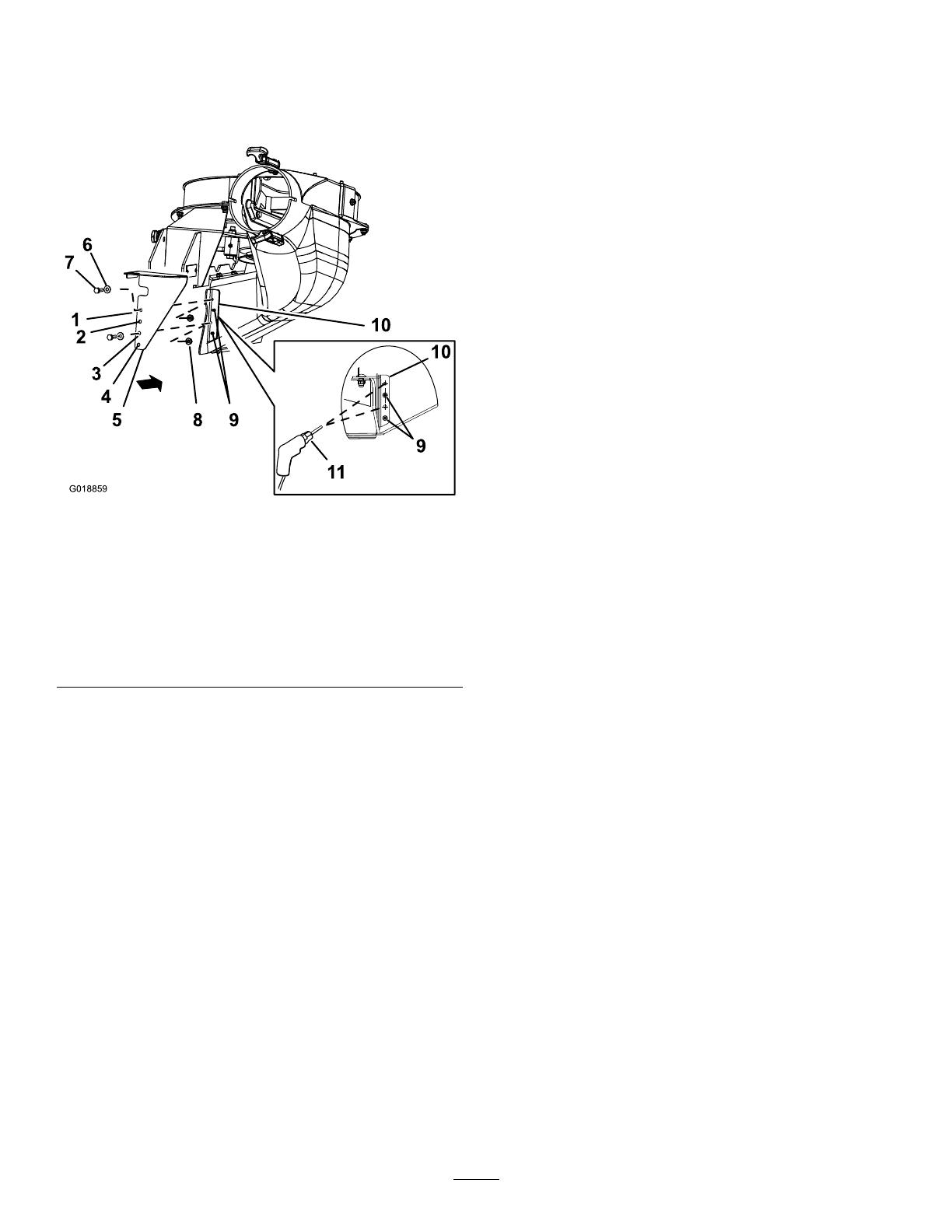
1.AlignthelowerCElowerguardtothe
blower-chutebracketasshowninFigure11.
g018859
Figure11
1.Hole1
7.Hex-headbolt(1/4x3/4
inch)
2.Hole2
8.Locknut(1/4inch)
3.Hole39.Rivettails
4.Hole410.Blower-chutebracket
5.CElowerguard11.Drillbit7mm(0.28inch)
6.Washer
2.Alignhole2andhole4ofthelowerCElower
guardtotherivettailsprotrudingthroughthe
blower-chutebracket(Figure11).
Note:EnsurethattheangeoftheCElower
guard(theangewiththeholes)isatagainst
theblower-chutebracket.
3.Marktheoutlineofhole1andhole3oftheCE
lowerguardontheblower-chutebracket,and
removetheCEguard(Figure11).
4.Locatethemarksontheblower-chutebracket,
andcenter-punchthelocations.
5.Drill7mm(0.28inch)holesintheblower-chute
bracketatthe2center-punchmarks(Figure11).
InstallingtheCELowerGuard
Note:InstalltheCElowerguardwiththeblower
assemblyremovedfromthemowerdeck;referto
theE-ZVac™BlowerandDriveKitInstallation
Instructions.
1.AligntheCElowerguardtotheblower-chute
bracket(Figure11).
2.Alignhole2andhole4oftheCElower
guardtotherivettailsprotrudingthroughthe
blower-chutebracket(Figure11).
3.SecuretheCElowerguardtotheblowerwith2
hex-headbolts(1/4x3/4inch),2washers,and
2locknuts(1/4inch)throughhole1andhole4
oftheCEguard(Figure11).
InstallingtheBlower
Ifyouremovedtheblower,installittothemowerdeck
asfollows:
Note:RefertotheBaggerKit(ToroModel78463)
manual.
1.Aligntheblowerbeltaroundthepulleyofthe
blower(Figure10).
2.Alignthepivotpinontheblowerwiththepivot
pinholeinthedeckandlowerthebloweronto
thedeck.
3.Opentheblowerlatchpin,closetheblowerto
thedeck,andsecurethelatchpintothechute
bracket(Figure9).
Note:Ensurethatthelatchpinextendsthrough
theholeinchutebracketandtheCEpulley
guard.
4.Temporarilyroutethebeltbeneaththeidler
pulley(Figure10).
5.Routethebeltaroundthedrivepulley(Figure
10).
6.Movetheidler/tensionpulleytowardthexed
springpost,andinstallthespringbyaligningthe
springhookontotheidlerspringpost(Figure9).
7.Pullthespringloadedidler/tensionpulleyaway
fromthexedspringpost,androutethebelt
aroundtheidlerpulley(Figure10).
10
8
InstallingtheCEBeltCover
Partsneededforthisprocedure:
1
Hex-headbolt(1/4x3/4inch)
1
Washer(5/16x3/4inch)
1
Washer(1/4x1/2inch)
1Retainer
InstallingtheCEBeltCoverBolt
1.Assemblethewasher(5/16x3/4inch)tothe
hex-headbolt(1/4x3/4inch)asshowninFigure
12.
g351271
Figure12
132cmMowerDeckShown
1.Washer(5/16x3/4inch)5.Washer(1/4x1/2inch)
2.Hex-headbolt(1/4x3/4
inch)
6.Retainer
3.Plasticplug
7.Clipnut
4.Beltcover
8.CEbelt-coverbracket
2.Inserttheboltandwasherthroughtheholein
thetopofthebeltcoverfromtheOEMblower
anddrivekit(Figure12).
3.Fromthebottomofthebeltcover,assemblethe
washer(1/4x1/2inch)andretaineroverthe
hex-headboltthreads(Figure12).
Ensurethattheboltheadandwasherare
positionedushwiththeuppersurfaceofthe
beltcoverandthewasherandretainerareush
withthebottomsurfaceofthecover.
InstallingtheBeltCover
1.Unlatchtheblowerandpullitoutpartially.
2.Alignthebeltcoverwithnotchesinthedeck
anges(Figure12).
3.Alignthehex-headboltinthecoverwiththeclip
nutonthebelt-coverbracket.
4.Securethebeltcovertothecoverbracketwith
thehex-headbolt(Figure12).
5.Installtheplasticplugintothecover(Figure12).
6.Opentheblowerlatchpin,closetheblowerto
thedeck,andsecurethelatchpintothechute
bracket.
11
9
InstallingtheNewLower
SupportRod
Partsneededforthisprocedure:
1Lowersupportrod
1
Flange-headbolt(1/4x3/4inch)
1
Locknut(1/4inch)
Procedure
1.Threadthenewlowersupportrodthroughthe
lowerskirtopening.
2.Securetherodusing1ange-headbolt(1/4x
3/4inch)and1locknut(1/4inch)asshownin
Figure13.
g351272
Figure13
1.Lowersupportrod
3.Flange-headbolt(1/4x
3/4inch)
2.Locknut(1/4inch)
12
10
InstallingtheHeight-of-Cut
CoverPlates
Partsneededforthisprocedure:
2
Height-of-cutcoverplate(122cmdecks)
2
Height-of-cutcoverplate(132cmand152cmdecks)
2
Locknut(1/4inch)
2
Carriagebolt(1/4x3/4inch)
122cmMowerDecks
Securethe2height-of-cutcoverplatestothe102to
140mmrangesoftheheight-of-cutbracketusing2
carriagebolts(1/4x3/4inch)and2locknuts(1/4inch)
asshowninFigure14andFigure15.
g351283
Figure14
1.Height-of-cutbracket3.Locknut(1/4inch)
2.Height-of-cutcoverplate
(122cmdecks)
4.Carriagebolt(1/4x3/4
inch)
g351823
Figure15
InstalledView
13
132cmand152cmMowerDecks
Securethe2height-of-cutcoverplatestothe133mm
and140mmrangesoftheheight-of-cutbracketusing
2carriagebolts(1/4x3/4inch)and2locknuts(1/4
inch)asshowninFigure16andFigure17.
g351284
Figure16
1.Height-of-cutbracket3.Height-of-cutcoverplate
(132cmand152cm
decks)
2.Locknut(1/4inch)4.Carriagebolt(1/4x3/4
inch)
g351824
Figure17
InstalledView
14
Notes:
1 / 1

Ask a question and I''ll find the answer in the document

Finding information in a document is now easier with AI

Ask the document