6
InstallingtheCEPulleyGuard
andBelt-CoverBracket
Partsneededforthisprocedure:
1
CEpulleyguard
1
CEbelt-coverbracket
1
Hex-headbolt(1/4x1inch)
1
Carriagebolt(1/4x3/4inch)
2
Flangenut(1/4inch)
2
Hex-headbolt(3/8x1inch)
2
Flangenut(3/8inch)
1
Clipnut
1
Rearguard(122cmmowerdeckonly)
InstallingtheCEPulleyGuardand
Belt-CoverBracket
For122cmMowerDecks
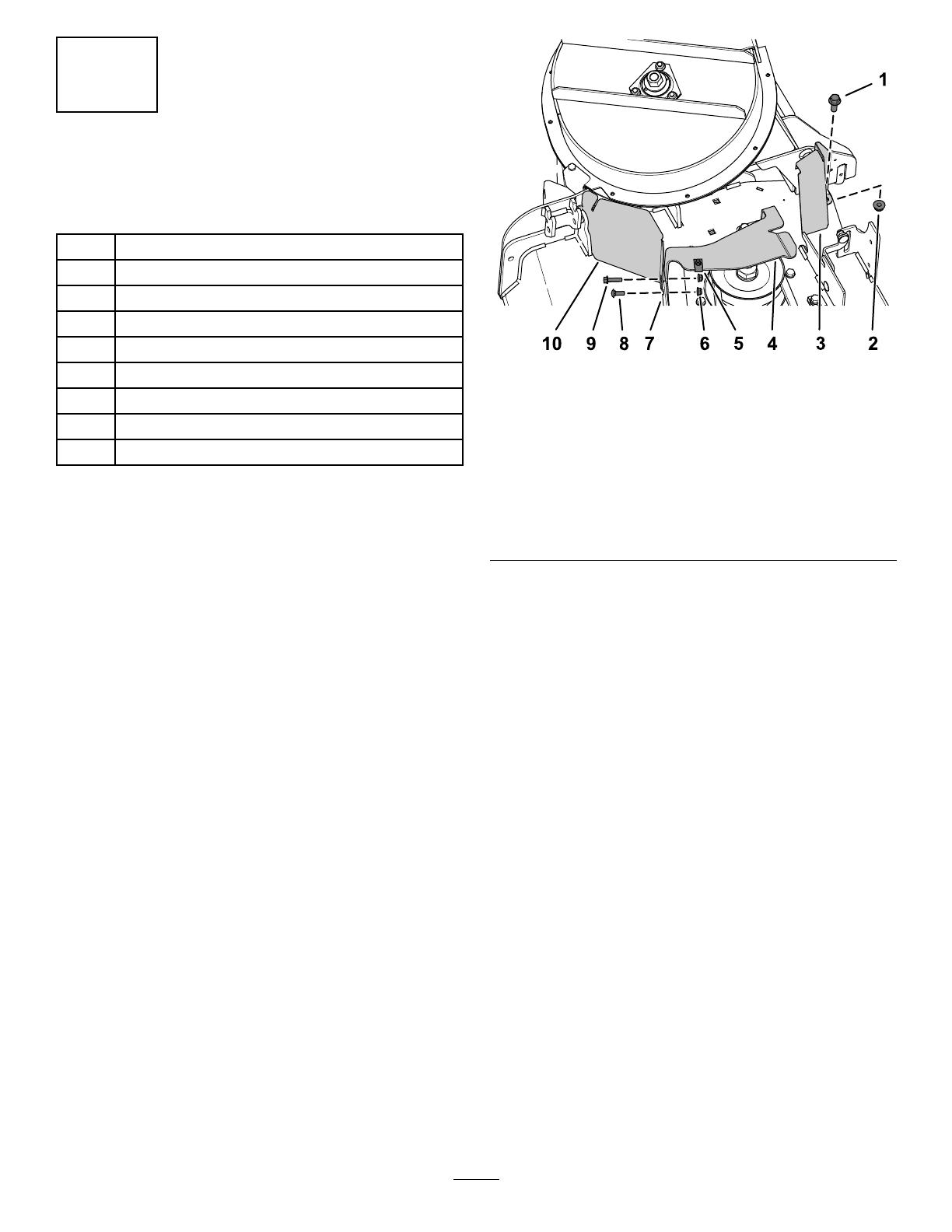
1.AligntheholesoftheCEpulleyguardtotheholein
theforwarddeectorbracketandtheoutboardholein
theforwarddeckange(Figure11).
Note:TheCEpulleybracketwrapsaroundthe
outboardedgeofthedeectorbracket
g203671
Figure11
1.Hex-headbolt(3/8x1
inch)
6.Flangenut(1/4inch)
2.Flangenut(3/8inch)7.Deckange(forward)
3.Rearguard(122cm
mowerdeckonly)
8.Carriagebolt(1/4x3/4
inch)
4.Belt-coverbracket
9.Flange-headbolt(1/4x1
inch)
5.Clipnut10.CEpulleyguard
2.AligntheCEbelt-coverbrackettotheholesattherear
sideoftheforwarddeckange(Figure11).
3.SecuretheCEpulleyguardandthebeltcoverbracket
totheforwarddeckangeattheoutboardholewith
thehex-headbolt(1/4x1inch)andaangenut(1/4
inch)asshowninFigure11.
4.Securethebelt-coverbrackettotheforwarddeckange
attheinboardholewiththeacarriagebolt(1/4x3/4
inch)andaangenut(1/4inch)asshowninFigure11.
5.AligntheholeintherearangeoftheCEbelt-cover
bracketwiththeholeinthedeckwhereyouremoved
theOEMbeltcoverbracketinstep1ofRemovingthe
CoverMountingBracket(page4);refertoFigure11.
6.SecuretherearangeoftheCEbelt-coverbracket
tothedeckwithahex-headbolt(3/8x1inch)anda
angenut(3/8inch)asshowninFigure11.
7.AligntheclipnutwiththeholeinthetopoftheCE
belt-coverbracket,andpushtheclipnutontothe
bracket(Figure11).
8.Looselyinstalltherearguardtothemowerdeckusing
ahex-headbolt(3/8x1inch)andaangenut(3/8
inch)asshowninFigure11.
Tightenthefastenersafteryouinstalltheblower;refer
toInstallingtheBlower(page11).
Important:Thisstepappliesto122cmmower
decksonly.
7