Page is loading ...

Safety Instructions, Installation & Operator’s Manual For
KIT No. 6-3073 & 6-3100
MMZ/OFZ GRASS CATCHER FOR
MID MOUNT & OUT FRONT Z-RIDER™
ZERO TURNING HYDRO DRIVE
SERIES 0 & 1
KIT #6-3073 for
Kohler Engine Models
KIT #6-3100 for
Kubota Engine Models
ZF2500KH
ZM2500KH
ZM2501KH
MZM2200KH
ZMT2500KH
ZF2100DKU
ZF2300GKU
COPYRIGHT © 2001
SNAPPER INC.
ALL RIGHTS RESERVED
MANUAL NO. 7-2018 (REV. 2, 1/30/01)

2
IMPORTANT SAFETY INSTRUCTIONS
WARNING: This powerful cutting machine is capable of amputating hands and feet and can throw objects that
can cause injury and damage! Failure to comply with the following SAFETY instructions could result in serious
injury or death to the operator or other persons. The owner of the machine must understand these instructions
and must allow only persons who understand these instructions to operate machine. Each person operating
the machine must be of sound mind and body and must not be under the influence of any substance which
might impair vision, dexterity or judgment. If you have any questions pertaining to your machine which your
dealer cannot answer to your satisfaction, call or write the Customer Service Department at SNAPPER,
McDonough, Georgia 30253. Phone: (1-800-935-2967).
PROTECTION FOR CHILDREN
Tragic accidents can occur if the operator is not alert
to the presence of children. Children are often
attracted to the machine and the mowing activity.
Never assume that children will remain where you last
saw them.
1. KEEP children out of the mowing area and under
the watchful care of a responsible adult.
2. DO NOT allow children in yard when machine is
operated (even with the blade OFF).
3. DO NOT allow children or other passengers to ride
on machine or on attachments (even with the
blade OFF). They may fall and be seriously
injured.
4. DO NOT allow pre-teenage children to operate
machine.
5. ALLOW only responsible adults & teenagers with
mature judgment under close adult supervision to
operate machine.
6. BE SURE the area is clear of others before
mowing and turn machine OFF if anyone enters
the area.
7. DO NOT mow in reverse unless absolutely
necessary. LOOK BEHIND and down for small
children before and when backing.
8. USE EXTRA CARE when approaching blind
corners, shrubs, trees, or other objects that may
obscure vision.
PROTECTION AGAINST TIPOVERS
Slopes are a major factor related to loss-of-control
and tip-over accidents, which can result in severe
injury or death. All slopes require extra CAUTION. If
you cannot back up the slope or if you feel uneasy on
it, DO NOT mow it. Use extra care with grass catchers
or other attachments; these can change the stability
of the machine.
1. DO NOT operate machine on slopes exceeding 10
degrees (18% grade).
2. Exercise EXTREME CAUTION on slopes. Turn
blade OFF when traveling uphill. Use first speed
and avoid sudden or sharp turns.
3. DO NOT mow back and forth across face of
slopes. Mow up and down.
PROTECTION AGAINST TIPOVERS
(Continued From Previous Column)
4. AVOID uphill starts. If machine stops going uphill
or tires lose traction, turn blade OFF and back
slowly down the slope.
5. STAY ALERT for holes and other hidden hazards.
Tall grass can hide obstacles. Keep away from
ditches, washouts, culverts, fences and
protruding objects.
6. KEEP A SAFE DISTANCE (at least 3 feet) away
from edge of ditches and other drop offs. The
mower could turn over if an edge caves in.
7. Always begin forward motion in the #1 (slow)
speed position.
8. Use weights in accordance with instructions with
grass catcher.
9. DO NOT put your foot on the ground to try to
stabilize the machine.
10. DO NOT mow on wet grass. Reduced traction
could cause sliding.
11. DO NOT mow under any condition where traction,
steering or stability is doubtful without first test
driving over the terrain with blade OFF.
12. Operator Protective Structures are available for
this machine through your local Snapper dealer.
PREPARATION
1. Read this manual, get to know where all controls
are located and practice how to use them before
starting for the first time, and at the beginning of
each season. Read and follow Warnings and
Instructions on engine and machine. Read and
follow operator’s manual and instructions
furnished with attachments.
2. Only mature, responsible persons shall operate
the machine and only after proper instruction.
3. Data indicates that operators age 60 and above,
are involved in a large percentage of mower-
related injuries. These operators should evaluate
their ability to operate the mower safely enough to
protect themselves and others from serious injury.
4. Handle fuel with extra care. Fuels are flammable
and vapors are explosive. Use only an approved
fuel container. Never remove fuel cap or add fuel
with engine running. Add fuel outdoors only with
engine stopped and cool. Clean spilled fuel from
machine. DO NOT smoke.
5. Practice operation of machine with BLADE OFF to
learn controls and develop skills.
(Continued on Next Page)

3
IMPORTANT SAFETY INSTRUCTIONS
PREPARATION
(Continued From Previous Page)
6. Check the area to be mowed and remove all
objects such as toys, wire, rocks, limbs and other
objects that could cause injury if thrown by blade
or interfere with mowing.
7. Keep people and pets a safe distance from
machine.
8. Check shields, deflectors, switches, blade
controls and other safety devices frequently for
proper operation and location.
9. Make sure all safety decals are clearly legible.
Replace if damaged.
10. Protect yourself when mowing and wear safety
glasses, long pants and substantial footwear.
11. Know how to STOP blade and engine quickly in
preparation for emergencies.
12. Use extra care when loading or unloading the
machine into a trailer or truck.
13. Check grass catcher components frequently for
signs of wear or deterioration and replace as
needed to prevent injury from thrown objects
going through weak or worn spots.
OPERATION
1. Mount and dismount machine from left side.
2. Start engine from operator's seat, if possible.
Make sure blade is OFF and parking brake is set.
3. STOP blade, STOP engine, set parking brake and
remove key when leaving machine.
4. DO NOT operate machine unless properly seated
with feet on feet rests or pedal(s).
5. STOP BLADE and ENGINE and make sure blade
has stopped before removing grass catcher or
unclogging mower to prevent loss of fingers or
hand.
6. Blade must be OFF except when cutting grass. Set
blade in highest position when mowing over
rough ground.
7. Keep hands and feet away from rotating blade
underneath deck. NEVER place foot on ground
while BLADE is ON or machine is in motion.
8. Deflector or entire grass catcher must be in place.
NEVER point discharge at people, passing cars,
windows or doors.
9. Slow down before turning.
10. Watch out for traffic when near or crossing
roadways.
11. STOP engine immediately after striking an
obstruction. Inspect machine and repair damage
before resuming operation.
12. Mow only in daylight or with good artificial light.
13. Move motion control levers SLOWLY to maintain
control during speed and directional changes.
14. Exercise CAUTION when pulling loads. DO NOT
pull loads greater than 300 pounds. Avoid jack
knifing. DO NOT turn sharply.
MAINTENANCE
1. Never store machine or fuel container inside
where fumes may reach an open flame, spark or
pilot light such as in a water heater, furnace,
clothes dryer or other gas appliance. Allow engine
to cool before storing machine in an enclosure.
Store fuel container out of the reach of children in
a well ventilated, unoccupied building.
2. Keep engine free of grass, leaves or excess
grease to reduce fire hazard and engine
overheating.
3. When draining fuel tank, drain fuel into an
approved container outdoors and away from open
flame.
4. Check brakes frequently; adjust, repair or replace
as needed.
5. Keep all bolts, nuts and screws properly tight.
Check that all cotter pins are in proper position.
6. Always provide adequate ventilation when running
engine indoors. Exhaust gases contain carbon
monoxide, an odorless and deadly poison.
7. Disconnect negative (black) cable from battery
before performing maintenance or service.
Cranking engine could cause injury.
8. Never work under machine without safety blocks.
9. Service engine and make adjustments only when
engine is stopped. Remove spark plug wire(s)
from spark plug(s) and secure wire(s) away from
spark plug(s).
10. DO NOT change engine governor speed settings
or overspeed engine.
11. Lubricate machine at intervals specified in manual
to prevent controls from binding.
12. Mower blades are sharp and can cut. Wrap the
blades or wear heavy leather gloves and use
CAUTION when handling them.
13. NEVER test for spark by grounding spark plug
next to spark plug hole; spark plug could ignite
gas exiting engine.
14. Have machine serviced by an authorized
SNAPPER dealer at least once a year and have the
dealer install any new safety devices.
15. Use only genuine SNAPPER replacement parts to
assure that original standards are maintained.

4
DECALS
46360
24773

5
TABLE OF CONTENTS
IMPORTANT SAFETY INSTRUCTIONS..................................................................... 2-3
DECALS .........................................................................................................................4
TABLE OF CONTENTS..................................................................................................5
SECTION I - INSTALLATION ....................................................................................6-15
Introduction.................................................................................................................................... 6
Blower Drive Belt Installation (All Models)........................................................................... 6
Discharge Adapter Installation ...........................................................................................6-7
Blade Installation - 61” Decks Only
....................................................................................... 7
Counterweight Installation - Mid Mount Models Only
......................................................... 7
Stand-Off Bracket Installation - Out Front Models Only
..................................................... 8
Cannister Plate/Stand-Off Bracket Assembly / Installation - Out Front Models............8-9
Cannister Plate Installation - Mid Mount Models Only
........................................................ 9
Assembling the Catcher Frame - Mid Mount And
Out Front Models............................9-10
Mounting the Blower Support Assembly.......................................................................10-12
A. Out Front Models Only
.........................................................................................10-11
B. Mid Mount Models Only
........................................................................................11-12
Container Top Assembly...................................................................................................... 13
Indicator Installation ............................................................................................................. 13
Container Top Installation.................................................................................................... 13
Grass Container Installation ...........................................................................................13-14
Grass Tube Installation....................................................................................................14-15
SECTION 2 - OPERATION & MAINTENANCE........................................................16-17
Introduction............................................................................................................................ 16
Grass Catcher Operation...................................................................................................... 16
Emptying Grass Cannister ................................................................................................... 16
Side-Discharging With Catcher Installed.......................................................................16-17
Clearing Clogs From Discharge Chute, Grass Tubes & Blower....................................... 17
Maintenance........................................................................................................................... 17
SECTION 3 - PARTS IDENTIFICATION..................................................................18-26
Contents................................................................................................................................. 18
Catcher Frame Assembly................................................................................................19-20
Blower, Idler, Adapter & Blade Assemblies...................................................................21-22
Catcher Assembly............................................................................................................23-24
Blower Assembly .............................................................................................................25-26
WARRANTY .................................................................................................................27
IMPORTANT
NOTICE: Operator Protective Structures are available as optional kits for the Mid-Mount and Out-Front
Z-Rider machines. These structures, when installed and used properly can offer additional security to
the operator against serious injury in the event of a tip over accident. Operator Protective Structures
may be required by local ordinances. Discuss your mowing application and ordinances with your local
Snapper Dealer.

6
SECTION I - INSTALLATION
INTRODUCTION
This section covers installation of the Snapper MMZ/OFZ
Grass Catcher for both the Mid Mount and Out Front
models of the Snapper Z-Rider, Zero Turning Hydro Drive,
Series 0. FAMILIARIZE YOURSELF WITH THIS
PRODUCT BEFORE YOU BEGIN INSTALLATION. See
Section 3, Pages 18 thru 26 for the PARTS DRAWINGS
and PARTS LISTS. Study these pages. Become familiar
with the parts, their method of assembly, and also, their
location.
Open the Hardware Bag and separate the nuts, bolts,
washers, etc. according to their size. Put the separated
fasteners into different bags/containers. This will speed
assembly time.
Read the following installation instructions carefully.
When you begin installation, make certain that you
follow the steps in sequence - as presented - this also
will save you time.
1.1 BLOWER DRIVE BELT INSTALLATION (All Models)
Install the blower drive belt as follows:
A. Depress belt idler and remove the inside
(forward) clutch drive belt. See Figure 1.1.
FIGURE 1.1
IMPORTANT: The grass catcher kit includes two
different length blower drive belts. Carefully check the
part numbers in insure you install the correct belt on
your machine.
1) Belt Part No. 7-2738 fits ZMT and Kubota powered
ZF machines.
2) Belt Part No. 4-6249 fits Kohler powered ZF, ZM &
MZM machines.
WARNING
DO NOT attempt any maintenance, adjustments or
service with engine running. STOP blades. STOP
engine. Set brake. Remove key. DO NOT operate
machine without entire grass catcher, deflector or
guards in place.
IMPORTANT: Some models are equipped with a single
belt drive. To install the catcher on those models, the
single groove pulley P/N 4-6969 must be replaced with
dual groove pulley P/N 7-
2388. The idler pulley
P/N 1-8573 must also be replaced with P/N 3-5867. On
MZM Models only, do not use existing P/N 5-8209 belt.
Replace with P/N 3-5543 found in kit.
B. Install blower drive belt on inside (forward) pulley
of electric clutch. Stretch belt out to the right hand
side and lay it over the frame rail.
C. Place the other belt in storage for later use.
1.2 DISCHARGE ADAPTER INSTALLATION
NOTE: The adapter kits are sold separately based
on the size deck on your machine.
61” Decks require Kit No. 6-3076.
52” Decks require Kit No. 6-3077.
Disconnect the battery cables. Remove the
negative (Black) cable first. Remove the positive
(Red) cable last.
Remove the chute deflector as follows:
A. Remove cotter pin.
B. Remove chute hinge pin and spring.
C. Remove deflector and store it, along with the
other parts, for later use. See Figure 1.2.
FIGURE 1.2
REMOVE INSIDE
CLUTCH DRIVE BELT
ELECTRIC CLUTCH
CONNECTOR
WIRING
HARNESS
CONNECTOR
REMOVE COTTER PIN, CHUTE
HINGE PIN, CHUTE SPRING &
DEFLECTOR (OUTFRONT Z,
61” DECK SHOWN)
SPRING
DEFLECTOR
HINGE PIN
COTTER
PIN

7
SECTION 1 - INSTALLATION
D. Install the discharge adapter. See Figure 1.3.
FIGURE 1.3
1.3 BLADE INSTALLATION - 61” DECKS ONLY
NOTE: Blade Part No. 2-9251 is included in
Adapter Kit Part No. 6-3076 for 61” Decks.
A. Apply parking brake.
B. Use a hydraulic floor jack or hoist to raise machine
high enough to gain access to the underside of deck.
Secure machine with safety blocks.
WARNING
Wear heavy leather gloves when handling or working
around cutting blades. Blades are extremely sharp
and can cause severe injury.
C. Remove discharge-side cutter blade and store for
later use. See Figure 1.4.
FIGURE 1.4
D. Use blade hardware previously removed to install
new kit blade to discharge-side cutter spindle. Refer
to Figure 1.4.
1.4 COUNTERWEIGHT INSTALLATION -
MID MOUNT MODELS ONLY
(KIT # 6-3078 - Purchased Separately)
In order to counteract the additional weight on the
rear of the Mid Mount Z Rider, owing to the
installation of the grass catcher, SNAPPER has
provided a counterweight kit which should be
installed as follows:
A. Align the 1” diameter hole in ballast plates with
the 1” diameter hole in the footplate. See Figure
1.5.
FIGURE 1.5
B. Using the two (2) 1/4” diameter holes located at
the front of the plates as drill guides, drill two (2)
1/4” holes thru the footrest.
C. Secure the plates to the footrest with (2) 1/4-20 x 1-
1/4” bolts (PN 91814) and (2) 1/4-20 Nyloc nuts (PN
91603) which were provided in the grass catcher kit.
WARNING
Ballast kit must be installed on Mid-Mount
machines before operation with catcher.
Grass catcher affects handling & stability of all
machines. Exercise extreme caution when
operating on slopes.
DO NOT operate machine on slopes greater than 10
degrees.
DO NOT mow across slopes - mow up & down.
DO NOT park machine on slopes.
INSERT PIN
THRU HOLE
SECUR
E WITH
COTTER PIN
DISCHARGE
ADAPTER
FASTEN HOOK
OVER LIP ON
DECK. PUSH DOWN
TO SECURE IN
PLACE.
LIP
HOOK
DISCHARGE
ADAPTER
(SEE FIG. 1.3)
DISCHARGE
-
SIDE CUTTER
SPINDLE (61” DECKS ONLY)
NEW BLADE
PART No. 2-9251
TORQUE BLADE
BOLT 70 TO 80
FT. LBS.
LAY PLATES ON
FOOTREST. ALIGN
WITH REAR HOLE.
1/4-20X1-1/4” BOLTS
NON
-
SKID, SELF
-
ADHESIVE PAD ON TOP
BALLAST PLATE
1” DIA. HOLE
(2) 1/4 DIA. HOLES
BALLAST
PLATES
FOOTPLATE
EXISTING 1
DIA. HOLE
(2) 1/4-20 NYLOC NUTS
DRILL (2) 1/4” HOLES
IN FOOTREST

8
SECTION 1 - INSTALLATION
1.5 STAND-OFF BRACKET INSTALLATION -
OUT FRONT MODELS ONLY
A. Attach stand-off bracket to the underside of the
cannister plate as shown in Figure 1.6.
NOTE: For OFZ Models with Kubota engine. Use
template provided in kit. Center the template on the
top of the back flange of the frame. Mark & drill two
(2) 3/8” diameter holes. Then proceed with step
1.5A.
FIGURE 1.6
B. Insert two (2) 3/8-16 x 5-1/4” bolts and 3/8” flat-
washers through the 1” diameter holes and stand-
off brackets as shown in Figure 1.7.
FIGURE 1.7
1.6 CANNISTER PLATE/STAND-OFF BRACKET
ASSEMBLY INSTALLATION - OUT FRONT
MODELS -
A. Remove the existing hardware which secures
the counterweights to the rear of the machine. See
Figure 1.8.
B. Mount the cannister plate/stand-off bracket
assembly to the counterweights. See Figure 1.8.
KUBOTA OFZ MODELS
A. To provide adequate clearance with the blower
structure, wide stance tail wheels must be installed
with the caster pivots towards the rear of the
machine. Figure 1.8 shows the axle with caster
pivots towards the front. You must reverse the
orientation of the axle using the following
instructions. The kit also includes a new axle stop
bracket Part No. 7-2041 to be used with the wide
stance tail wheels that will be installed at this time.
1. Jack up rear frame of machine to remove
weight off of caster wheels. Block machine
securely to prevent it from rolling and falling.
2. Remove dust cap from center axle pivot.
3. Remove retaining ring from axle pivot and
slide axle off of pivot shaft.
4. Reverse axle so that caster pivots are
towards the rear, but do not install axle at this
time.
5. Remove axle pivot weldment from rear of
frame by removing the four nuts.
6. Install axle stop bracket onto bolts used to
mount axle pivot weldment. Install stop bracket
with “L” shaped leg at bottom and facing
towards rear of machine.
7. Reinstall axle pivot weldment and secure
with nuts removed in Step 5. Tighten nuts
securely.
8. Install axle over axle pivot insuring caster
pivots face the rear. Secure axle in place with
retaining ring.
9. Reinstall dust cap.
B. Align holes in standoff bracket with the holes in
the back flange of the OFZ frame. See Note at
1.5A.
C. Secure plate/stand-off bracket assembly to
frame using (2) P/N 91497 HHCS, 3/8-16 x 1-1/2”,
(2) P/N 91514 FW 13/32 x 13/16 x 5/64 and (2)
91299, and HNYL 3/8-16 YZ.
D. Replace PTO clutch shield on Kubota engine
with new shield included in kit. The shield is
mounted to the rear of engine below the muffler.
1. Locate shield at the rear of engine and
remove the two mounting bolts from engine
block.
2. Install new shield and tighten bolts
securely.
CARRIAGE BOLTS
(4x)
CANNISTER
PLATE
STANDOFF BRACKET
N
YLOC NUTS
(4x)
3/8-16 x 5-1/4” LG. GR. 5 BOLTS
3/8” FLATWASHER
1” DIA. HOLES IN
CANNISTER
PLATE
STANDOFF BRACKET
OUT FRONT Z ONLY

9
SECTION 1 - INSTALLATION
FIGURE 1.8
1.7 CANNISTER PLATE INSTALLATION -
MID MOUNT MODELS ONLY
A. Fit front lip of cannister plate over the machine’s
rear cross member. See Figure 1.9.
FIGURE 1.9
B. Clamp the cannister plate to the crossmember.
Make sure that the plate is properly centered and
aligned and that the front lip is firmly against the
crossmember.
C. Using the two (2) outermost holes in the plate as
drill guides, drill two 5/16” diameter holes in the
crossmember.
D. Attach plate to crossmember with hardware as
shown in Figure 1.9. Remove clamps.
1.8 ASSEMBLING THE CATCHER FRAME -
MID MOUNT AND
OUT FRONT MODELS
NOTE: The catcher frame may come partially
assembled. Refer to Figure 1.10 for location of
parts.
A. Lay the two (2) upright angles on a flat surface
with the “half-moon” cutouts facing up. Refer to
Figure 1.10.
B. Fit the cross brace channel over the two upright
angles. Secure with provided hardware.
FIGURE 1.10
C. Mount the assembled upright angles and cross
brace channel to the cannister plate with provided
hardware.
D. Install the two (2) plate support straps.
E. Mount the heat shield to the inside of the upright
angles.
F. Attach the lower hinge bracket to the top of the
cross brace channel.
G. Attach the retainer plate and stop bracket.
NOTE: Retainer plate should be free to turn. DO
NOT overtighten.
DUST
CAP
CASTER PIVOT
CANNISTER
PLATE/STANDOFF
BRACKET ASSEMBLY
COUNTERWEIGHTS
NYLOC NUTS
NYLOC NUTS
(FRONT LIP)
CANNISTER
PLATE
FIT FRONT LIP OVER
CROSSMEMBER AS
INDICATED BY ARROW
REAR CROSSMEMBER
(MID MOUNT)
SCREWS
CROSS BRACE
CHANNEL
UPRIGHT
ANGLE
PLATE
SUPPORT
STRAP
STOP
BRACKET
RETAINER
PLATE
CANNISTER PLATE
PLATE
SUPPORT
STRAP
HEAT
SHIELD
UPRIGHT
ANGLE
CHUTE
HANGER
LOWER HINGE
BRACKET

10
SECTION 1 - INSTALLATION
1.8 ASSEMBLING THE CATCHER FRAME -
MID MOUNT AND
OUT FRONT MODELS
NOTE: At this point of assembly, place an
adjustable support - small jack, etc. - beneath the
end of the cannister plate. It must be level and the
upright angles must be vertical. Place a level on the
plate. Adjust the support until the plate is level.
Next, place the level against the upright angles. If
required, loosen, and then retighten hardware until
the upright angles are vertical.
1.9 MOUNTING THE BLOWER SUPPORT ASSEMBLY
A. OUT FRONT MODELS ONLY
1. Place blower support assembly into position on
the right rear corner of the frame as follows:
(a) Place tab over top of frame rail. See Figure
1.11.
(b) Align rear holes in support assembly with
bottom holes in catcher frame assembly.
FIGURE 1.11
(c) Fit the bottom tab under the frame rail. Refer to
Figure 1.11.
2. Install the idler pulley assembly as shown in
Figure 1.12.
IMPORTANT KUBOTA OFZ MACHINES
The kit contains two idler arms. Use the long idler
arm on Kubota machines. After installing the idler
arm check for clearance between the fuel line and
the idler pulley. A wire tie has been provided in the
kit. Use the wire tie to secure the fuel line away
from the idler pulley being careful not kink the line.
NOTE: Remove two nuts from blower assembly
before mounting to the blower support.
3. Attach the blower assembly to the support as
shown in Figure 1.13.
4. Install belt as shown in Figure 1.14 and align
idler pulley, blower pulley and engine drive pulley
using belt. Align by moving blower support and
blower.
5. Mark holes in side of frame using blower support
plate as a template.
FIGURE 1.12
FIGURE 1.13
FIGURE 1.14
P/N 72399 ATTACHES FROM BLOWER SUPPORT TO GEAR BOX
MOUNT USING (4) P/N 91508 & (4) P/N 91298
BLOWER ASSEMBLY
BLOWER SUPPORT
BLOWER BRACE
SLOTTED
HOLES
NUTS
CATCHER FRAME ASSEMBLY
ALIGN WITH HOLES IN CATCHER
FRAME ASSEMBLY
PLACE TAB OVER TOP OF
R.H. FRAME RAIL
FRAME
SUPPORT
ASSEMBLY
THIS TAB
FITS UNDER
FRAME RAIL
IDLER
SPRING
FLAT
WASHER
IDLER
PULLEY
IDLER
PIVOT SHAFT
COTTER
PIN
BUSHINGS
LOCKNUT
MOVE BLOWER
& SUPPORT TO
ALIGN BELT
ENGINE
DRIVE
PULLEY
IDLER PULLEY
BLOWER
PULLEY

11
SECTION 1 - INSTALLATION
1.9 MOUNTING THE BLOWER SUPPORT ASSEMBLY
OUT FRONT MODELS ONLY
6. Drill three (3) 5/16” diameter holes in the frame
and secure blower support assembly with five (5)
5/16-18 x 3/4” carriage bolts and Nyloc nuts.
NOTE:
For Kubota OFZ Models, skip steps 7 &
8.
7. Install blower support brace to side of blower
support as shown in Figure 1.15.
8. Slide brace toward frame. Then mark and drill
one (1) 5/16” diameter hole. Secure brace with two
(2) 5/16”-18 x 3/4” carriage bolts, one (1) 5/16-18 x
1” hex bolt, and three (3) 5/16-18 Nyloc nuts.
FIGURE 1.15
9. Loosen the two blower nuts, which interfere with
installation, then position belt guard in place as
shown. Secure using four (4) 5/16” self-tapping
screws. Retighten the two nuts. See Figure 1.16.
NOTE: Kubota OFZ Models require the removal of
the chrome extension from the muffler to install belt
guard.
10. Mount the left hand brace to the left hand side
of the catcher frame assembly. Mark holes in frame
and drill four (4) 5/16” diameter holes in side of
frame. See Figure 1.17.
FIGURE 1.16
FIGURE 1.17
1.9 MOUNTING THE BLOWER SUPPORT ASSEMBLY
B. MID MOUNT MODELS ONLY
1. Place blower support assembly into position on
the right rear corner of the frame.
2. Align the blower support assembly with the four
(4) holes in the side of the frame and secure with
four (4) 5/16-18 x 3/4” carriage bolts and Nyloc
nuts.
3. Secure blower support assembly to catcher frame
using two (2) 5/16-18 x 3/4” carriage bolts and Nyloc
nuts.
4. Install the idler pulley assembly as shown in
Figure 1.12.
5. Attach the blower assembly to the support as
shown in Figure 1.13. Leave room for adjustment.
6. Install belt onto idler and blower pulleys as
shown in Figure 1.14. Align idler pulley, blower
pulley, and engine drive pulley using belt.
7. Once aligned, tighten the blower assembly to the
support.
DRILL FOUR (4) HOLES
AND SECURE BRACE
WITH CARRIAGE BOLTS
AND LOCKNUTS
SECURE
BRACE TO
CATCHER
FRAME WITH
CARRIAGE
BOLTS AND
LOCK-NUTS
LEFT HAND
BRACE
KOHLER OFZ MODELS
KUBOTA
OFZ
MODELS
DRILL (1) 5/16 DIA.
HOLE IN FRAME
B
LOWER SUPPORT BRACE.
(NOT NEEDED FOR KUBOTA OFZ
MODELS)
HEX BOLT
NYLOC NUT
CARRIAGE
BOLTS
NYLOC
NUTS
KOHLER
OFZ MODEL
SHOWN
BELT GUARD
SELF
-
TAPPING
SCREWS
LOOSEN NUTS
FROM ONE
BLOWER BOLT ON
EACH SIDE.
RETIGHTEN NUTS
AFTER GUARD IS IN
PLACE.

12
SECTION 1 - INSTALLATION
1.9 MOUNTING THE BLOWER SUPPORT ASSEMBLY
B. MID MOUNT MODELS ONLY
8. Install belt guard. Refer to Figure 1.16.
9. Mount the left hand brace to the left hand side of
frame. See Figure 1.18.
10. After all parts have been installed, check pulley
and belt alignment again. If everything is O.K.,
tighten all nuts and bolts.
FIGURE 1.18
1.10 CONTAINER TOP ASSEMBLY
A. Attach the container inlet weldment and internal
discharge deflector to the container top as shown in
Figure 1.19.
FIGURE 1.19
FIGURE 1.20
B. Insert latch rod into latch top on container top.
See Figure 1.21, Steps 1, 2, & 3.
1. Insert long end of latch rod thru left hand hole as
shown in Figure 1.21.
FIGURE 1.21
2. Continue to feed long end of latch rod thru left
hand hole until the short end can be fed thru R.H.
hole by compressing center section with fingers.
3. Secure the short end of the latch rod with a
retainer. Refer to Figure 1.21.
LEFT HAND BRACE
CARRIAGE BOLTS &
LOCKNUTS
CARRIAGE BOLTS &
LOCKNUTS
CATCHER FRAME UPRIGHT
CONTAINER TOP
INLET
WELDMENT
CARRIAGE
BOLTS
LOCKNUTS
INTERNAL
DEFLECTOR
CONTAINER TOP
MOUNT SCREEN TO
INSIDE OF OPENING
1/4
-
20x3/4” HEX HEAD
BOLTS
1/4” FLATWASHERS
1/4-15 PLASTIC SCREWS
TOP COVER
LATCH TOP
RETAINER
COMPRESS
LATCH ROD
(FOLLOW STEPS
1,2 & 3 TO INSERT
INTO LATCH TOP)

13
SECTION 1 - INSTALLATION
1.10 CONTAINER TOP ASSEMBLY
C. Attach deflector to container top. See Figure
1.22.
FIGURE 1.22
D. INDICATOR INSTALLATION
1. Assemble and install the indicator as shown in
Figure 1.23.
FIGURE 1.23
1.11 CONTAINER TOP INSTALLATION
Attach container top to catcher frame as shown in
Figure 1.24.
FIGURE 1.24
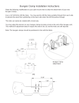
1.12 GRASS CONTAINER INSTALLATION
A. Insert “S” hook thru hole in bungee mount as
shown in Figure 1.25.
B. Crimp “S” hook to help prevent loss of bungee.
FIGURE 1.25
CONTAINER TOP
1/4
-
20 NYLOC
NUTS
1/4
-
20x3/4” HEX HEAD
BOLT
DEFLECTOR
INDICATOR
1/4-20 NUT
1/4
-
20x3/4” HEX
HEAD CAPSCREW
1/4-20 NUT
BASE
1/4-20 NUT
DRIVER
ASSEMBLY
HOLD LATCH ROD “UP”
DURING ASSEMBLY
LATCH TOP
5/16
-
18
NYLOC
NUT
5/16
-
18x4
-
1/2”
HEX HEAD
SCREW
LATCH BASE
CATCHER
FRAME
INSERT “S” HOO
K
THROUGH MOUNT
BUNGEE
LOWER “S”
HOOK
BUNGEE MOUNT
HINGE
SHIELD

14
SECTION 1 - INSTALLATION
1.12 GRASS CONTAINER INSTALLATION
C. Lift up on container top until it latches.
D. Place the catcher container onto the cannister
plate.
E. Lift up slightly on container top while lifting up
on latch rod. Lower container top onto container.
See Figure 1.26.
FIGURE 1.26
F. Secure the container by extending the bungee
and placing the “S” hook in the hole. See Figure
1.27.
FIGURE 1.27
1.13 GRASS TUBE INSTALLATION
A. Attach short grass tube to inlet on container
top and secure with clamp. See Figure 1.28.
FIGURE 1.28
CONTAINER TOP
(LIFT UP SLIGHTLY
WHILE LIFTING UP ON
LATCH ROD)
LATCH ROD
REMOVE “S” HOOK TO
“OPEN” COVER.
INSERT “S” HOOK TO
“LOCK” COVER.
CATCHER
CONTAINER
CANNISTER
PLATE
HOLE
“S”
HOOK
BUNGEE
CONTAINER TOP
INLET
CLAMP
GRASS
TUBE

15
SECTION 1 - INSTALLATION
1.13 GRASS TUBE INSTALLATION
B. Attach the other end of the short grass tube to
the blower discharge flange and secure with a
clamp. Refer to Figure 1.29.
FIGURE 1.29
C. Attach the long grass tube to the blower
intake.
Secure with a clamp.
D. Remove mower discharge adapter and attach
to the end of this grass tube. Secure with a
clamp.
E. Stretch the tube/discharge adapter assembly
until pin aligns with hole in deck. Insert pin
through hole. Secure pin with washer & cotter pin.
Push rear of adapter down until hook fastens
completely over lip on deck.
NOTE:
When installing tube for Mid-Mount
Models, it may be necessary to trim the tube. The
tube should be stretched tight between the
blower and deck adapter so that it does not drag
the ground. Tube can be trimmed with a razor
knife or hacksaw.
Installation is now complete.
GRASS TUBE
CLAMP
LOCKNUT
BLOWER
DISCHARGE
FLANGE
BLOWER
CARRIAGE
BOLT

16
SECTION 2 - OPERATION & MAINTENANCE
INTRODUCTION
For operation & maintenance of the Out Front and Mid
Mount Z-Riders, refer to their respective operator’s
manuals. Operation of the MMZ/OFZ Grass Catcher is
an integral part of the blade operation of both Z-Riders.
WARNING
DO NOT operate machine without entire grass
catcher, deflector or guards in place.
2.1 GRASS CATCHER OPERATION
A. After the engine has been started; the grass
catcher blower will be activated when the blade
switch is pulled “OUT" See Figure 2.1.
FIGURE 2.1
B. When mowing, grass is discharged into the
cannister at the rear of the mower. As the grass
enters the cannister, it causes the indicator located
on the top cover to spin. When the indicator slows,
or stops, the cannister should be emptied. See
Figure 2.2.
FIGURE 2.2
WARNING
DO NOT turn around to inspect indicator when
mowing. STOP the machine, place the joystick in
Neutral (N) and engage the Parking Brake Lever. Then
turn to see if indicator is in motion or stopped.
2.2 EMPTYING GRASS CANNISTER
A. Stop blades. Push blade switch “IN”.
B. Stop engine by turning key to the “OFF” position.
C. Apply parking brake.
D. Remove “S” hook (bungee) from hole in top
cover.
E. Raise top cover until it latches in the “UP”
position. Latch engages automatically when cover
is lifted.
F. Remove the grass cannister.
G. Dispose of grass trimmings according to local,
state & Environmental Protection Agency codes
and regulations.
H. Reinstall grass cannister in reverse order.
I. Manually remove latch. First lift container top
cover removing weight off of latch. Raise latch while
at the same time lowering top cover. Secure cover
with bungee hook.
NOTE: When emptying grass container, check the
indicator mechanism under the top cover to insure
that it is operating correctly. Clean mechanism of
any debris buildup.
2.3 SIDE DISCHARGING WITH CATCHER INSTALLED
A. If you wish to “Side-Discharge” the grass
clippings for a short period with the catcher
installed, place discharge adapter in chute hanger
and secure with washer and hairpin. See Figure
2.3.
B. Install the discharge deflector previously
removed on the mower deck.
FIGURE 2.3
BLADE
SWITCH
PULL “OUT” TO ENGAGE
BLADE & BLOWER.
PUSH “IN” TO DISENGAGE
BLADE & BLOWER.
CONTROL PANEL
(OUT FRONT & MID MOUNT Z-RIDERS)
INDICATOR TOP COVER
A
-
SPINS AS GRASS IS BLOWN
INTO CANNISTER.
B - STOPS WHEN CANNISTER
IS FULL.
GRASS TUBE
HANGER
DISCHARGE
ADAPTER
WASHER
HAIRPIN

17
SECTION 2 - OPERATION & MAINTENANCE
2.3 SIDE DISCHARGING WITH CATCHER INSTALLED
C. If you wish to “Side Discharge” the clippings for
an extended period of time with the catcher in place
perform Steps A & B above and, also remove the
blower belt from the blower pulley and engine
pulley.
NOTE: The clutch drive belt removed in Step 1.1
should be reinstalled at this time.
2.4 CLEARING CLOGS FROM DISCHARGE CHUTE,
GRASS TUBES & BLOWER.
The grass catcher may become plugged with
clippings if grass conditions are too severe or the
machine is used improperly. If plugging occurs,
attempt the following:
1. Ground speed too fast - cut at slower speed.
2. Engine speed too slow - set engine speed control
to “FAST” position.
3. Removing too much grass - raise cutting height
and cut lawn more frequently.
4. Grass is too wet from dew or rain - allow grass to
dry.
5. Blades are too dull or worn - inspect blades and
replace as necessary. Use only genuine SNAPPER
replacement blades.
6. Incorrect blade(s) - catcher operation requires
high lift blade(s). Check to make sure proper blades
are installed. The 52” mower comes equipped with
high lift blades. The 61” mower requires the
installation of a high lift blade on the discharge
spindle only and comes as part of the kit.
7. Deck, deck adapter, blower or tubes have
clipping build up - clean all clippings from all
internal surfaces.
WARNING
DO NOT put fingers or hands inside fan! STOP
blades. STOP engine. Remove key. Use only a stick,
or other suitable means, to clear the fan of clogs or
other obstructions!
WARNING
DO NOT attempt any adjustments, maintenance or
repairs with engine running. STOP blades. STOP
engine. Remove key.
WARNING
Grass Catcher components are subject to
deterioration. Inspect frequently. Replace worn or
damaged components immediately. Use only genuine
SNAPPER replacement parts.
A. TO CLEAR A PLUGGED GRASS TUBE OR
DISCHARGE ADAPTER
1. Stop blades and blower. Stop engine. Remove
key.
2. After all rotating components (engine, blower,
blades) have come to a complete stop, remove
discharge adapter from deck.
3. Clear any obstructions from adapter and tube.
Use a stick to reach into the tube.
4. Install discharge adapter.
B. TO CLEAR A PLUGGED BLOWER
1. Stop blades and blower. Stop engine. Remove
key.
2. After all rotating components have come to a
complete stop, loosen the hose clamps at the inlet
and outlet of the blower.
3. Remove grass tubes from blower.
4. Using a stick or similar object, clear all
obstructions. DO NOT INSERT HAND.
5. Reinstall grass tubes to blower and securely
tighten hose clamps.
2.5 MAINTENANCE
Grass catcher components are subject to wear and
deterioration. All components must be inspected
frequently. Inspect the following before each use.
1. Grass Tubes. Check tubes for wear, tears and
holes. Replaced as needed.
2. Blades. Check blades for sharpness, wear,
flatness and damage. Refer to OFZ/MMZ
Operator’s Manual for blade wear limits and
sharpening/replacement instructions.
3. Blower. Check blower impeller, blower housing
and inlet/outlets for signs of wear and deterioration.
Replace as needed. Check all fasteners and
hardware to insure none are missing and all are
tightened securely.
4. Belts. Check belts for wear and fraying. Replace
as needed.
5. Idler Arm. Lubricate idler arm bushing with 1 to 3
shots of General Purpose grease from a grease
gun. Check idler arm to insure it pivots freely and
bushings are not worn. Replace worn bushings as
needed.
6. Gear Box. Right angle drive gear box requires
no maintenance. Inspect for signs of leakage. If
leakage is observed contact your local SNAPPER
Dealer for assistance.

18
SECTION 3 – PARTS IDENTIFICATION
CONTENTS
ITEM PAGE NO.
Catcher Frame Assembly............................................................................. 19-20
Blower, Idler, Adapter & Blade Assemblies ............................................... 21-22
Catcher Assembly........................................................................................ 23-24
Blower Assembly.......................................................................................... 25-26

19
CATCHER FRAME ASSEMBLY
BUCKET GRASS CATCHER
* NOTE: This part is required on
OFZ units only.
12
12

20
CATCHER FRAME ASSEMBLY
ITEM PART NO. DESCRIPTION
1 4-1994 BRACKET, Lower Hinge
2 4-1981 ANGLE, Upright (2)
3 4-6187 STRAP, Plate Support (2)
4A 4-6192 BRACE, Left Hand Grass Catcher (MMZ)
4B 4-6389 BRACE, Left Hand Grass Catcher (OFZ)
5 4-1988 CHANNEL, Cross Brace
6 4-6189 BRACKET, Stop
7 4-1999 Plate, Canister
8A 4-6190 BRACKET, Standoff, Grass Catcher (Kohler OFZ Models Only)
8B 7-2389 BRACKET, Standoff, Grass Catcher (Kubota OFZ Models Only)
9 4-6184 PLATE, Retainer
10 5-7778 ASSEMBLY, Heat Shield & Decal (Includes item 11)
11 4-6403 DECAL, Heat Shield
12 9-1508 BOLT, 5/16-18 x 3/4” Short Neck Carriage, Grade 5 (33)
13 9-1298 NUT, 5/16-18 Nyloc (39)
14 9-0998 BOLT, 5/16-18 x 4-1/2” Hex Head, Grade 2
15 2-7168 SCREW, 5/16-18 x 1” Hex Head Cap, Grade 5 (5)
16A 9-1982 SCREW, 3/8-16 x 5-1/4” Hex Head Cap, Gr. 5 (2) (Kohler OFZ Models)
16B 9-1497 SCREW, 3/8-16 x 1-1/2” Hex Head Cap, Gr. 5 (2) (Kubota OFZ Models)
17 9-1514 WASHER, 13/32 I.D. x 13/16 O.D. Flat (3) (OFZ Only)
18 9-1299 NUT, 3/8-16 Hex Nyloc (OFZ Only)
19 7-2040 BRACKET, Chute Hanger
20 4-5293 SHIELD, PTO Clutch (Kubota Models Only)
21 9-1315 WASHER, .32 Split Lock (2)
22 9-1933 SCREW, M8-1.25 x 25MM HHC (2)
BUCKET GRASS CATCHER
/