
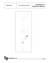
Series 200
Insertion Style Flow Sensors
Installation & Operation Manual
872020-EN (August 2012)
Rev. 8
IMPORTANT:
This manual contains important information.
READ AND KEEP FOR REFERENCE.

Series 200 Flow Sensors
Contents
INTRODUCTION . . . . . . . . . . . . . . . . . . . . . . . . . . . . . . . . . . . . . . . . . . . . . . . . . . . . . . . . .3
MECHANICAL INSTALLATION . . . . . . . . . . . . . . . . . . . . . . . . . . . . . . . . . . . . . . . . . . . . . . . . .3
General . . . . . . . . . . . . . . . . . . . . . . . . . . . . . . . . . . . . . . . . . . . . . . . . . . . . . . . . . . . .3
INSTALLATION FOR 220BR, 220SS . . . . . . . . . . . . . . . . . . . . . . . . . . . . . . . . . . . . . . . . . . . . . .3
Installation Procedure . . . . . . . . . . . . . . . . . . . . . . . . . . . . . . . . . . . . . . . . . . . . . . . . . . .3
Alignment of Flow Sensor. . . . . . . . . . . . . . . . . . . . . . . . . . . . . . . . . . . . . . . . . . . . . . . . .4
HOT TAP INSTALLATION FOR 225BR, 226BR, and 226SS. . . . . . . . . . . . . . . . . . . . . . . . . . . . . . . . .4
If the Pipe is Depressurized and Drained . . . . . . . . . . . . . . . . . . . . . . . . . . . . . . . . . . . . . . .5
INSTALLATION INTO A PRESSURIZED PIPELINE USING MODEL HTT . . . . . . . . . . . . . . . . . . . . . . . . .5
ELECTRICAL INSTALLATION "STANDARD" SENSORS . . . . . . . . . . . . . . . . . . . . . . . . . . . . . . . . . . .6
ELECTRICAL INSTALLATION "IR" SENSORS . . . . . . . . . . . . . . . . . . . . . . . . . . . . . . . . . . . . . . . . .6
ELECTRICAL INSTALLATION "HIGH TEMPERATURE" SENSORS . . . . . . . . . . . . . . . . . . . . . . . . . . . . .7
ELECTRICAL INSTALLATION . . . . . . . . . . . . . . . . . . . . . . . . . . . . . . . . . . . . . . . . . . . . . . . .7
CALIBRATION . . . . . . . . . . . . . . . . . . . . . . . . . . . . . . . . . . . . . . . . . . . . . . . . . . . . . . . . . . .9
Calibration Tables . . . . . . . . . . . . . . . . . . . . . . . . . . . . . . . . . . . . . . . . . . . . . . . . . . . . . .9
IMPELLER ASSEMBLY AND SHAFT REPLACEMENT . . . . . . . . . . . . . . . . . . . . . . . . . . . . . . . . . . . 12
TROUBLESHOOTING. . . . . . . . . . . . . . . . . . . . . . . . . . . . . . . . . . . . . . . . . . . . . . . . . . . . . . 12
SPECIFICATIONS . . . . . . . . . . . . . . . . . . . . . . . . . . . . . . . . . . . . . . . . . . . . . . . . . . . . . . . . 13
Page 2 August 2012

Installation & Operation Manual
the impeller friction to increase, which may affect
performance at low flow rates. Any circumferential
location is correct for installation in vertical pipes.
3. An insertion depth of 1-1/2 inches for pipe sizes
2.5 inches and larger is required for accurate flow
rate calibration. Detailed installation instructions
for various sensor mounting configurations on the
following pages include methods for ensuring correct
insertion depth.
4. Alignment of the sensor to ensure that impeller
rotation is parallel to flow is important. Alignment
instructions are also included on the following pages.
INSTALLATION FOR 220BR, 220SS
Installation Procedure
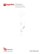
The insertion depth and alignment of the sensor assembly
are critical to the accuracy of the flow measurement. The
flat end of the sensor tube assembly MUST BE INSTALLED
1-1/2 inches from the inside wall of the pipe. In order to
allow for variations in wall thickness, lining, or coatings the
depth adjustment is controlled by the position of the Hex
Nuts on the three threaded studs of the hex mounting
adapter. The hex mounting adapter is provided with a 2
inch male NPT connection.
There are two methods of mounting these sensors in a
2.5 inch or larger pipe. One is with a 2 inch NPT threaded
pipe saddle. The other is with a welded-on fitting such as
a Thredolet®, also tapped for a 2 inch NPT connection. In
either case, cut a 2 inch hole through a depressurized pipe
and then secure the saddle or weld-on fitting to the pipe.
(For drilling into a pressurized pipe, see instructions for
Series 225 and 226 sensors.) Install the 2 inch NPT adapter
provided, using a thread sealant to prevent leakage.
Tighten as necessary. Badger Meter insert style sensors are
calibrated with the sensor inserted 1-1/2 inches into the
pipe flow.
To determine the proper insertion depth, proceed as
follows:
1. Apply anti-seize thread lubricant , supplied with
the sensor, to the threaded studs of the mounting
adaptor.
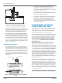
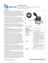
2. Insert the depth gauge into the mounting adapter
and set it against the inside wall of the pipe as shown.
Set the top of the upper adjusting nut to 3-3/4 inches
as measured. Lock it in place with the bottom nut on
the same stud. Repeat for the other adj. nuts.
Note: For Model 220PVS - set nuts 6.5 inches above inside wall of pipe.
INTRODUCTION
Used in conjunction with any Badger Meter impeller flow
monitor or transmitter, Badger Meter non-magnetic flow
sensors provide an accurate rate of liquid flow as well as
total accumulated flow. A number of sensor models are
offered, which cover applications for a wide range of pipe
sizes and pressure/temperature specifications.
The flow sensors generate a frequency which is
proportional to flow rate. An internal preamplifier allows
the pulse signal to travel up to 2000 feet without further
amplification. Power to operate the sensor is provided by
the flow monitor. The impeller bearing assembly, shaft and
O-rings are replaceable in the field.
Badger Meter flow sensors feature a closed, six-bladed
impeller design, using a proprietary, non-magnetic
sensing technology. The forward-swept impeller shape
provides higher, more constant torque than four-bladed
impeller designs, and is less prone to fouling by water-
borne debris. The forward-curved shape, coupled with the
absence of magnetic drag, provides improved operation
and repeatability, even at lower flow rates. As the liquid
flow turns the impeller, a low impedance signal is
transmitted with a frequency proportional to the flow rate.
Sensors of similar type are interchangeable, so there is no
need for recalibration after servicing or replacement.
MECHANICAL INSTALLATION
General
Flow measurement accuracy for all flow measuring
devices is highly dependent on proper location in the
piping system. Irregular flow velocity profiles caused by
valves, fittings, pipe bends, etc. can lead to inaccurate
overall flow rate indications although local flow velocity
measurement may be accurate. A sensor located where
it can be affected by air bubbles, floating debris, or
sediment may not achieve full accuracy and could be
damaged. Badger Meter flow sensors are designed
to operate reliably under adverse conditions, but the
following recommendations should be followed to ensure
maximum system accuracy:
1. Choose a location along the pipe where 10
pipe diameters upstream and 5 pipe diameters
downstream of the sensor provide no flow
disturbance. Pipe bends, valves, other fittings, pipe
enlargements and reductions should not be present
in this length of pipe.
2. The preferred location around the circumference of a
horizontal pipe is on top. If trapped air or debris will
interfere, then the sensor should be located further
around the pipe from the top but not more than 45
degrees from top center. The sensor should never
be located at the bottom of the pipe, as sediment
may collect there. Locations off top center cause
Page 3 August 2012

Series 200 Flow Sensors
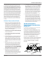
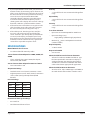
3 ¾”
20345
Adjusting Nuts
Figure 1: Installation for 220BR and 220SS
3. Clean O-rings and flow sensor sleeve, and lightly
lubricate O-rings with silicone grease from the packet
provided or some other acceptable lubricant. Take
care not to get grease on the impeller or bearing.
4. Insert the flow sensor into the 2 inch NPT adapter so
that the mounting holes in the positioning collar fit
over the studs on the adapter. Lower the sensor onto
the previously adjusted nuts. Install the lock nuts on
top of the positioning collar and tighten. Now tighten
the lower jam nuts firmly against the upper adjusting
nuts to secure them for future removal of the sensor
for inspection or service.
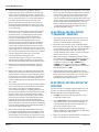
Alignment of Flow Sensor
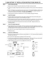
1. Loosen positioning collar set screws with a 3/32 inch
Allen wrench. Place the alignment rod through the
sight holes in the flow sensor. Refer to Figure 2. Using
the alignment rod as a guide, align the flow sensor so
that the flow label arrow matches pipe flow direction
and so that the alignment rod is exactly parallel to the
pipe. This procedure aligns the impeller directly into
the fluid flow.
SET SCREW
ALIGNMENT ROD
ALIGNMENT ROD
C
C
Figure 2: Alignment of Flow Sensor in 220BR and
220SS
2. As a backup to the flow arrow label, there is a
small hole next to the larger sighting hole of the
upstream side. With a 3/32 inch Allen wrench, tighten
positioning collar set screws.
3. Double check that the sighting holes in the sleeve are
parallel down the pipe and that the flow arrow label
matches pipe liquid flow direction.
4. Cable routing: The positioning collar is threaded for
connection of a standard 1/2 inch electrical conduit
(flex cable) or a wire strain relief. Route cable as
required. Be sure to leave enough flex in cable or
conduit to allow future removal of sensor for service
or cleaning if necessary.
HOT TAP INSTALLATION FOR
225BR, 226BR, AND 226SS
Badger Meter Series 200 hot tap style liquid flow sensors
are designed for use in cases where pipelines will be in
continuous service and depressurizing or draining the
system for installation or service is not practical.
The Series 200 hot tap sensors are designed to be installed
either in a depressurized pipe by hand or “Hot Tapped”
into a pressurized pipeline. Both installation procedures
are listed in this installation and operation manual. If
there is the slightest possibility that the pipe could be
full or pressurized, FOLLOW THE INSTALLATION FOR
PRESSURIZED PIPE.
Refer to Figure 3 for location or identification of the
various parts described in the following procedures.
The insertion depth and alignment of the sensor assembly
are critical to the accuracy of the flow measurement. The
flat end of the sensor tube assembly MUST BE INSTALLED
1-1/2 inches from the inside wall of the pipe. In order to
allow for variations in wall thickness, lining or coatings
the depth adjustment is controlled by the position of the
hex nuts on the three threaded studs of the hex mounting
adapter. The hex mounting adapter is provided with a
2 inch male NPT connection. Both gate and ball valve
units are provided with 2 inch nipples for mounting onto
saddles, weld-o-lets, etc.
Depth setting is accomplished by positioning the hex
nuts 14-7/8 inches minus the thickness of the pipe, from
the outside diameter of the pipe. For example, measure
the wall thickness of the pipe from the coupon removed
when the 1-7/8 inch hole was cut into the pipe. If the pipe
was 1/8 inch thick, subtract 1/8 inch from 14-7/8 inch, or
position the nuts 14-3/4 inch from the outside diameter of
the pipe. This will allow the 16-3/8 inch sensor to protrude
1-1/2 inch into the pipe.
Apply anti-seize thread lubricant, supplied with the
sensor, to the threaded studs of the mounting adaptor.
Page 4 August 2012

Installation & Operation Manual
The alignment of the impeller with the flow in the pipe
is accomplished by aligning the two “sight holes” at the
top of the sensor tube assembly with the center line of
the pipe. Make sure the alignment is made to the pipe
and not to a wall or surface near the sensor. To adjust,
loosen the two set screws in the positioning collar with
a 3/32 inch Allen wrench provided in the Series 200 hot
tap installation kit. Slip one end of the 1/4 inch x 18 inch
steel rod (also supplied in the installation kit) through the
holes in the sensor tube. Rotate the sensor tube until the
rod is centered on the pipe. Ensure the flow label “Arrow”
on the sensor matches the liquid flow direction. Tighten
the positioning collar Allen screws to lock the sensor
tube assembly in position. Note: As a backup to the flow
direction arrow label on the tube assembly, there is a
smaller hole located beside one of the sighting holes in
the tube, to also indicate the upstream side of the tube
assembly.
If the Pipe is Depressurized and Drained
1. Drill or cut a 1-7/8 inch hole in the pipe with a drill
or hole saw. Note the pipe wall thickness for use in
calculating sensor assembly depth. A location on the
top of the pipe is best for overall performance and
service life; however, any radial location on the top
half of the pipe is acceptable. Allow a minimum of ten
pipe diameters upstream and five downstream from
the sensor of straight unobstructed pipe to allow full
development of the flow profile.
2. Install either a service saddle or welded pipe fitting (2
inch female NPT) on the outside diameter of the pipe
over the 1-7/8 inch hole.
3. Install the Badger Meter isolation valve and nipple
onto the fitting using pipe thread sealant or Teflon®
tape on all threads.
4. Install the Badger Meter hex mounting adapter onto
the valve assembly. Use pipe thread sealant on the
adapter. Tighten the hex adapter so that no stud is
aligned with the center-line of the pipe. This could
interfere with final sensor alignment. Measure depth
and set the height of the nuts of the hex mounting
adapter.
5. Open the bleed petcock valve on the hex adapter to
relieve the pressure as the sensor tube is installed.
Carefully hand insert the Badger Meter hot tap flow
sensor tube into the hex mounting adapter. The
sleeve should be inserted past the top two O-rings in
the adapter (approx. 1 to 1-1/4 inches). Take care not
to push the tube in too far as the impeller could be
damaged if it strikes the closed valve.
6. Even if the sensor is installed with system drained,
Badger Meter recommends that a HTT, hot tap
insertion/removal tool be purchased for future
service. This tools allows the sensor tube assembly to
be removed from the pipe line without draining the
entire loop where the sensor is mounted.
7. In a fully depressurized and drained pipe, the sensor
tube assembly may be installed by hand. Carefully
and very slowly open the isolation valve to relieve
any pressure that may have built up. Fully open the
isolation valve. Push the sensor tube into the pipe
with a slight twisting motion. Guide the sensor
collar holes over the three hex adapter studs until
the collar rests on the nuts. Hex nuts should have
been previously set to the correct height. Install the
three lock nuts onto these studs at the top of the
positioning collar and securely tighten.
8. Loosen the two set screws in the positioning collar
with a 3/32 inch Allen wrench. Align the sensor
sight holes along the pipe axis using the alignment
rod provided in the installation kit supplied with
the sensor. Ensure that the flow label arrow on the
sensor matches the liquid flow direction inside the
pipe. Tighten the positioning collar set screws. Note:
As a backup to the flow label arrow, there is a small
hole located beside one of the sighting holes to also
indicate the upstream side of the sensor.
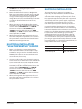
INSTALLATION INTO A
PRESSURIZED PIPELINE USING
MODEL HTT
For information on installing hot tap sensor with older
225H consult technical bulletin DID-001.
For pipe sizes 2½” and above; all Badger Meter sensors
are inserted 1 1/2” from the inside wall of the pipe. The
insertion depth is controlled by the position of the hex
nuts on the three threaded rods. The formula below
defines the distance between the top of the sensor hex
mounting adaptor and the bottom of the positioning
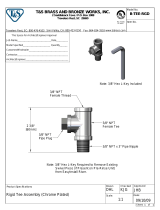
collar (the top of the hex nut). Reference Figure 3.
D = 16 3/8” - ( H + Pipe Wall Thickness + 1.5 “ )
Example: If sensor is installed in a 8 inch Sch 80 pipe with
a pipe wall thickness of 1/2 inch and the “H” dimension is
10 inches then the calculation would be as below:
D = 16 3/8 - ( 10 inches + 0.5 inches + 1.5 inches)
D = 4 3/8”
BLEED VALVE
HEX NUT
JAM NUT
Figure 3:
Page 5 August 2012

Series 200 Flow Sensors
1. Set one set of hex/jam nuts so that the distance
between the top surface of the hex nut and the top
surface of the hex mounting adaptor is equal to the
“D” dimension calculated above. Then adjust the other
two sets of hex/jam nuts 1-1/2 inches below the first
jam nut to allow clearance for the tool top yoke.
2. Remove the tool split ring and clevis pin and slide
tool bottom yoke into the groove on the sensor hex
mounting adaptor and secure by replacing the clevis
pin and split ring.
3. Mark sleeve 2-3/4 inches from impeller end of metal
sleeve. This mark is a stopping point to insure that
impeller/bearing is not damaged. Open the bleed
petcock valve on the hex adapter to relieve the
pressure resulting from the sensor tube insertion.
Carefully hand insert the Badger Meter hot tap
flow sensor sleeve assembly into the hex mounting
adapter until the mark lines up with the top of the
hex mounting adapter. At this point the sleeve will
have been inserted past the top two “O”-rings in the
adapter (approx. 1 1-1/4 inches). Take care not to push
the sensor past the mark on the sleeve as the impeller
could be damaged if it strikes the closed valve.
4. Fully extend tool by turning drive nut
counterclockwise with a 15/16 inch socket or box
wrench (not provided) until drive nut contacts tool
and slide the positioning collar into the tool top yoke.
5. Rotate tool so the threaded rod with the adjusted
hex/jam nuts is centered in the top yoke of hot tap
tool.
6. Rotate sensor sleeve so positioning collar holes align
with the threaded rods and flow direction label is in
general direction making sure the positioning collar is
located in the recessed area of the top yoke. Slide the
top yoke of the tool over the positioning collar and
secure by tightening the two thumbscrews on the top
of the yoke.
7. Close the bleed petcock and slowly open the isolation
valve. Slowly turn the 15/16 inch drive nut clockwise
to insert the sensor tube assembly through the
valve and into the pipeline. Carefully guide the three
threaded studs of the hex mounting adapter through
the holes of the sensor positioning collar. Carefully
lower the sensor until the positioning collar contacts
the hex nut preset for the correct depth adjustment.
Install the three lock nuts onto the threaded rods,
tightening only the lock nut on the threaded rod with
the preset hex/jam nut; then, bring the two remaining
lock nuts down until they just contact the positioning
collar. Do not tighten at this time
8. Remove the Model HTT Insertion/Removal Tool, by
loosening the two thumbscrews, removing the clevis
pin and then sliding the insertion tool off the sensor.
Then bring the two remaining sets of hex/jam nuts up
to the underside of the positioning collar, and tighten.
9. Align the sensor by first loosening the two set screws
in the side of positioning collar with a 3/32 inch Allen
wrench. Then align the sensor sight holes along the
pipe axis using the alignment rod provided in the
sensor installation kit. Ensure that the flow label arrow
on the sensor matches the liquid flow direction inside
the pipe. Tighten the positioning collar set screws.
Note: As a backup to the flow label arrow, there is
a small hole located beside the sight hole on the
upstream side of the sensor.
ELECTRICAL INSTALLATION
"STANDARD" SENSORS
1. The metal collar on the top of the 220 sensors or an
optional conduit cap on the Series 250 sensors will
accept 1/2 inch threaded conduit fittings.
2. Route the cable from the sensor to a Badger Meter
flow monitor/transmitter. The cable may be extended
up to 2000 feet, using 2-conductor shielded 20 AWG
or larger stranded copper wire. Be sure to leave
enough flexibility in the cable or conduit to allow for
future service of sensor, if necessary.
3. When connecting to a Badger Meter flow monitor/
transmitter, locate the section of terminal strip on the
monitor labeled “SENSOR INPUT” or “SENSOR”.
Connect the red wire to “ IN”, "SIGNAL(+)" or
"SIGNAL" terminal and the black wire to “GND",
"SIGNAL(-)”, or "COM" terminal and the shield drain
wire (if applicable) to “SLD”.
4. When interfacing with other equipment, consult
manufacturer for input designations. The signal wave
forms and power requirements are as shown in the
specifications section. Refer to Technical Bulletin
DTB-058 at www.badgermeter.com.
ELECTRICAL INSTALLATION "IR"
SENSORS
The sensor leads are supplied with watertight caps over
the ends. See Application Note DAB-031 and Technical
Bulletin DID-003 at www.badgermeter.com.
1. DO NOT remove the plastic caps from the sensor
leads until ready to splice.
2. Use a twisted pair cable suitable for direct burial to
connect the sensor to the transmitter, monitor, or
controller. Multi-pair telecommunication cable or
direct burial cables may be used.
3. Make a water tight splice. Two part epoxy type
waterproof kits are recommended. Be sure the epoxy
seals the ends of the cable jacket.
4. Make sure the epoxy is hardened before inverting the
splice or dropping it in standing water.
Page 6 August 2012

Installation & Operation Manual
5. DO NOT make an underground splice unless
absolutely necessary.
6. Route the cable from the sensor to a Badger Meter
flow monitor/transmitter. The cable may be extended
up to 2000 feet, using 2-conductor shielded 20 AWG
or larger stranded copper wire with appropriate
ratings. Be sure to leave enough flexibility in the cable
or conduit to allow for future service of sensor, if
necessary.
7. When connecting to a Badger Meter flow monitor/
transmitter, locate the section of terminal strip on the
monitor labeled “SENSOR INPUT” or “SENSOR”.
Connect the red wire to “IN”, "SIGNAL(+)" or
"SIGNAL" terminal and the black wire to “GND",
"SIGNAL(-)”, or "COM" terminal and the shield drain
wire (if applicable) to “SLD”.
8. When interfacing with other equipment, the signal
wave forms and power requirements are as shown in
the specifications section. Refer to technical bulletin
DTB-058 at www.badgermeter.com.
ELECTRICAL INSTALLATION
"HIGH TEMPERATURE" SENSORS
1. Route a cable from the sensor to a Badger Meter
flow monitor/transmitter. The cable may be run up
to 2000 feet, using 2-conductor shielded 20 AWG or
larger stranded copper wire. Be sure to leave enough
flexibility in the cable or conduit to allow for future
service of sensor, if necessary.
2. Connect to cable inside sensor electronic housing on
Series 220 sensors or attach to the sensor cable on the
Series 225/226 and connect with standard wire nuts.
3. When connecting to a Badger Meter flow monitor or
transmitter, locate the section of terminal strip on the
monitor labeled “SENSOR INPUT” or “SENSOR”.
Connect the red wire to “ IN”, "SIGNAL(+)" or
"SIGNAL" terminal and the black wire to “GND",
"SIGNAL(-)”, or "COM" terminal and the shield drain
wire (if applicable) to “SLD”.
4. When interfacing with other equipment, the signal
wave forms and power requirements are as shown in
the specifications section.
ELECTRICAL INSTALLATION
The Series 200 sensor is approved, as an entity, as
intrinsically safe when installed in conformance with
Badger Meter installation drawing 06-480-002 as specified
on the blue label identifying an intrinsically safe sensor.
Entity approval implies that only the sensor is approved
as intrinsically safe. Unless power supplies, equipment,
and instruments connected to the sensor are each
rated either explosion-proof or intrinsically safe, these
devices cannot be installed in a hazardous area. The
referenced installation drawing shows such apparatus
located in a non-hazardous location. Proper interfacing
between the hazardous and non-hazardous areas must be
provided. It is of absolute importance that this interface
be constructed and that all wiring be performed by
qualified contractors. To ensure the intrinsic safety of
the installation, the connection of the intrinsically safe
sensor to instruments and or power supplies must take
place using an approved intrinsically safe barrier located
in a non-hazardous area. These barriers, listed below, are
readily available from various suppliers.
Manufacturer: Barrier:
Crouse-Hinds Spec 504 Cat No.SB19140M0715
Measurement Technology Ltd. MTL 715+ 15 V
R Stahl Intrinspak 9001/1-158-150-10
Page 7 August 2012

Series 200 Flow Sensors
Page 8 August 2012

Installation & Operation Manual
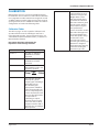
CALIBRATION
Badger Meter sensors use unique K and Offset numbers
for calibration. These numbers are derived from calibration
runs using NIST traceable instruments. Using both a K and
an Offset number provides higher accuracy than using a K
(pulse/gal) factor alone. K and Offset numbers for each tee
configuration are listed in the following tables.
Calibration Tables
The table on pages 12 and 13 provides calibration and
operation data for most scheduled pipe sizes from 3
inches through 18 inches. For tee-mounted sensors, see
either Metal Tee (Manual Number 872021), or (Plastic Tee
Manual Number 872022).
Description of Column Information for
Pipe Sizes 3 inches through 36 inches
Column 1 Nominal Pipe Size
Column 2 Pipe O.D. as defined by
ASA B36.10 and other
standards
Column 3 Pipe I.D. as defined by
ASA B36.10 and other
standards
Columns 4 and 5 The K value and Offset
that should be used in our
frequency equation:
Freq=
Gpm
K
- Offset
This equation describes
the frequency of the
output signal of all Badger
Meter flow sensors.
By substituting the
appropriate K and Offset
values from the table, the
sensor’s output frequency
can be calculated for each
pipe size. This information
is required when
calibrating an output
board or when using the
raw sensor data as direct
output to interface with a
device that is not a Badger
Meter product.
Column 6 This column indicates the
suggested flow range of
sensors in each pipe size.
Badger Meter sensors
will operate both above
and below the indicated
flow rates. However, good
design practice dictates
the use of this range for
best performance.
Sensors should be sized for
flow rather than pipe size.
To prevent disturbances
to the flow profile, always
conntect the sensor
tee to the pipe nipples
measuring at least ten pipe
diameters in length on
the downstream (delivery)
side before making the
transition in pipe size.
Page 9 August 2012

Series 200 Flow Sensors
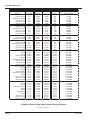
Column 1 Column 2 Column 3 Column 4 Column 5 Column 6
Suggested Operating
Pipe Size Pipe O.D. Pipe I.D. K Offset Range (GPM)
3 inch Sch 10S 3.500" 3.260" 5.009 .090 12-400
Std. Wt., Sch 40 3.5" 3.068" 4.362 .063 12-400
Extra Strong, Sch 80 3.5" 2.900" 3.858 .043 12-400
PVC Class 125 3.5" 3.284" 5.094 .093 12-400
PVC Class 160 3.5" 3.230" 4.902 .085 12-400
PVC Class 200 3.5" 3.166" 4.682 .076 12-400
4 inch Sch 10S 4.5" 4.260" 9.597 .241 20-600
Std. Wt., Sch 40 4.5" 4.026" 8.34 .229 20-600
Extra Strong, Sch 80 4.5" 3.826" 7.354 .188 20-600
PVC Class 125 4.5" 4.224" 9.396 .240 20-600
PVC Class 160 4.5" 4.154" 9.013 .240 20-600
PVC Class 200 4.5" 4.072" 8.578 .239 20-600
5 inch Sch 10S 5.563" 5.295" 16.305 .250 30-900
Std. Wt., Sch 40 5.50" 5.047" 14.674 .248 30-900
Extra Strong, Sch 80 5.50" 4.813" 13.165 .246 30-900
6 inch Sch 10S 6.625" 6.357" 24.089 .260 50-1,500
Std. Wt., Sch 40 6.5" 6.065" 21.574 .257 50-1,500
Extra Strong, Sch 80 6.5" 5.761" 19.457 .254 50-1,500
PVC Class 125 6.625" 6.217" 22.853 .258 50-1,500
PVC Class 160 6.625" 6.115" 21.968 .257 50-1,500
PVC Class 200 6.625" 5.993" 21.068 .256 50-1,500
8 inch Sch 10S 8.625" 8.329" 43.914 0.286 80-2,500
Sch 20 8.625" 8.125" 41.653 0.283 80-2,500
Sch 30 8.625" 8.071" 41.063 0.283 80-2,500
Std. Wt., Sch 40 8.625" 7.981" 40.086 0.281 80-2,500
Sch 60 8.625" 7.813" 38.288 0.279 80-2,500
Extra Strong, Sch 80 8.625" 7.625" 36.315 0.276 80-2,500
PVC Class 125 8.625" 8.095" 41.324 0.283 80-2,500
PVC Class 160 8.625" 7.961" 39.869 0.281 80-2,500
PVC Class 200 8.625" 7.805" 38.203 0.279 80-2,500
10 inch Sch 10S 10.75" 10.420" 70.195 0.321 125-4,000
Sch 20 10.75" 10.250" 67.668 0.318 125-4,000
Sch 30 10.75" 10.136" 66.069 0.316 125-4,000
Sch 40, Std.Wt. 10.75" 10.020" 64.532 0.314 125-4,000
Extra Strong, Sch 60 10.75" 9.750" 61.016 0.309 125-4,000
Sch 80 10.75" 9.564" 58.644 0.306 125-4,000
PVC Class 125 10.75" 10.088" 65.431 0.315 125-4,000
PVC Class 160 10.75" 9.924" 63.272 0.312 125-4,000
PVC Class 200 10.75" 9.728" 60.733 0.309 125-4,000
12 inch Sch 10S 12.75" 12.390" 104.636 0.367 175-5,000
Sch 20 12.75" 12.250" 102.553 0.364 175-5,000
Sch 30 12.75" 12.090" 99.347 0.36 175-5,000
Std. Wt., Sch 40S 12.75" 12.000" 97.576 0.358 175-5,000
Sch 40 12.75" 11.938" 96.369 0.356 175-5,000
Sch 60 12.75" 11.625" 90.441 0.348 175-5,000
Extra Strong 12.75" 11.750" 92.775 0.351 175-5,000
Sch 80 12.74" 11.376" 85.922 0.342 175-5,000
PVC Class 125 12.75" 11.966" 96.912 0.357 175-5,000
PVC Class 160 12.75" 11.770" 93.152 0.352 175-5,000
PVC Class 200 12.75" 11.538" 88.842 0.346 175-5,000
Calibration Table for Pipe Sizes 3 Inches Through 36 Inches
Continued on Next Page
Page 10 August 2012

Installation & Operation Manual
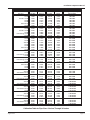
Column 1 Column 2 Column 3 Column 4 Column 5 Column 6
Suggested Operating
Pipe Size Pipe O.D. Pipe I.D. K Value Offset Range (GPM)
14 inch Sch 10S 14.00" 13.500" 122.307 0.391 200-6,000
Sch 20 14.00" 13.375" 120.216 0.388 200-6,000
Std. Wt., Sch 30 14.00" 13.250" 118.151 0.385 200-6,000
Sch 40 14.00" 13.124" 116.096 0.382 200-6,000
Sch 60 14.00" 12.814" 111.148 0.376 200-6,000
Extra Strong 14.00" 13.00" 114.098 0.33 200-6,000
Sch 80 14.00" 12.50" 106.299 0.369 200-6,000
16 inch Sch 10S 16.00" 15.500" 159.243 0.44 300-9,000
Sch 20 16.00" 15.375" 156.742 0.436 300-9,000
Std. Wt., Sch 30 16.00" 15.250" 154.267 0.433 300-9,000
Sch 60 16.00" 14.688" 143.456 0.419 300-9,000
Extra Strong, Sch 40 16.00" 15.000" 149.394 0.427 300-9,000
Sch 80 16.00" 14.314" 136.548 0.41 300-9,000
18 inch Sch 10S 18.00" 17.500" 202.739 0.498 350-10,000
Sch 20 18.00" 17.375" 199.828 0.494 350-10,000
Sch 30 18.00" 17.124" 194.061 0.486 350-10,000
Std. Wt. 18.00" 17.250" 196.943 0.49 350-10,000
Sch 40 18.00" 16.876" 188.464 0.479 350-10,000
Sch 60 18.00" 16.500" 180.171 0.469 350-10,000
Extra Strong 18.00" 17.000" 191.25 0.482 350-10,000
Sch 80 18.00" 16.126" 172.152 0.457 350-10,000
20 inch Std. Wt., Sch 20 20.00" 19.25" 246.179 0.555 400-12,000
Sch 40 20.00" 18.812" 234.836 0.540 400-12,000
Extra Strong, Sch 30 20.00" 19.000" 239.666 0.547 400-12,000
Sch 80 20.00" 17.938" 213.14 0.511 400-12,000
22 inch Std. Wt., Sch 20 22.00" 21.25" 301.975 0.621 500-15,000
Extra Strong, Sch 30 22.00" 21.00" 294.642 0.616 500-15,000
Sch 80 22.00" 19.75" 259.513 0.573 500-15,000
24 inch Std. Wt., Sch 20 24.00" 23.25" 364.331 0.666 600-18,000
Extra Strong 24.00" 23.00" 356.178 0.660 600-18,000
Sch 40 24.00" 22.624" 344.109 0.652 600-18,000
Sch 80 24.00" 21.562" 311.271 0.628 600-18,000
26 inch Sch 10 26.00" 25.376" 437.809 0.719 700-21,000
Std. Wt. 26.00" 25.25" 433.247 0.716 700-21,000
Sch 20, Extra Strong 26.00" 25.00" 424.274 0.709 700-21,000
28 inch Sch 10 28.00" 27.376" 513.698 0.774 900-23,000
Std. Wt. 28.00" 27.25" 508.723 0.770 900-23,000
Extra Strong, Sch 20 28.00" 27.00" 498.930 0.763 900-23,000
30 inch Sch 10 30.00" 29.376" 596.147 0.833 1,000-30,000
Std. Wt. 30.00" 29.25" 590.759 0.829 1,000-30,000
Sch 20, Extra Strong 30.00" 29.00" 580.146 0.822 1,000-30,000
32 inch Sch 10 32.00" 31.376" 685.156 0.897 1,200-35,000
Std. Wt. 32.00" 31.25" 679.355 0.893 1,200-35,000
Sch 20, Extra Strong 32.00" 31.00" 667.922 0.885 1,200-35,000
Sch 40 32.00" 30.624" 650.919 0.873 1,200-35,000
34 inch Sch 10 34.00" 33.312" 777.566 0.964 1,300-40,000
Std. Wt. 34.00" 33.25" 774.511 0.962 1,300-40,000
Extra Strong, Sch 20 34.00" 33.00" 762.258 0.953 1,300-40,000
Sch 40 34.00" 32.624" 744.022 0.940 1,300-40,000
36 inch Sch 10 36.00" 35.376" 882.855 1.040 1,500-45,000
Std. Wt. 36.00" 35.25" 876.227 1.035 1,500-45,000
Sch 20, Extra Strong 36.00" 35.00" 863.154 1.025 1,500-45,000
Sch 40 36.00" 34.50" 837.315 1.007 1,500-45,000
Calibration Table for Pipe Sizes 3 Inches Through 36 Inches
Page 11 August 2012

Series 200 Flow Sensors
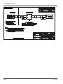
IMPELLER ASSEMBLY AND SHAFT
REPLACEMENT
If you are replacing an existing Badger Meter sensor and
have already calibrated your flow monitor/transmitter,
no calibration changes are necessary. For installation of
a new flow monitor or for relocation of a sensor in a new
pipe size, please refer to the calibration instructions in
flow monitor manual.
1. Depressurize pipe from which sensor is to be
removed. If the sensor is one of the Series 225/IR225
or 226/IR226, consult the installation section on hot
tap sensors.
NEVER disturb the securing lock nuts with pipe under
pressure without hot tap insertion tool Model HTT
installed.
2. Remove the three lock nuts that secure the
positioning collar to the threaded rods of metal
sensor.
NOTE: Before removing lock nuts, record the dimension
from top of 2 inch NPT adapter to the bottom of the
positioning collar. This dimension will be required later to
reinstall.
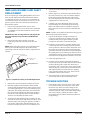
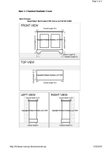
NOTE DIRECTION OF ARROW
USE PLIERS HERE
NOTE DIRECTION OF
IMPELLER
USE METAL PIN TO
REMOVE CERAMIC SHAFT
Figure 4: Impeller Assembly and Shaft Replacement
3. Remove the sensor from the hex adapter or the tee.
4. Note the impeller blade orientation relative to flow
arrows and the alignment hole in metal sensors beside
one of the sighting holes. In order to maintain proper
calibration, the impeller will have to be reinstalled in
the same manner with the impeller blades pointing
toward the small alignment hole, and into the flow
direction as indicated by the flow arrows.
5. To remove the old impeller blade assembly, push the
old shaft out of the sleeve with the new shaft (or small
diameter rod) just far enough to grab the end with a
pair of pliers and pull the shaft completely out. The
impeller assembly will now be free and will drop out.
6. Inspect the shaft and bearings for wear, and replace
as necessary.
7. Refer to figure 4. To reinstall, position the impeller in
the cavity oriented as in step 4 so that the impeller
blades point into the flow direction and toward
the small alignment hole located beside one of the
sighting holes on metal sensors.
8. Carefully push the shaft through the sleeve and
impeller taking care not to damage the bearings.
Make sure that the shaft is inserted far enough so
that it clears the sleeve on each side of the impeller
housing.
NOTE: If shaft is not carefully installed, the bearing can be
deformed preventing free rotation.
9. Inspect the O-rings for damage and replace as
necessary. Clean the O-rings and the sleeve and
relubricate with silicone grease from the packet
provided or some other acceptable lubricant.
10. Install the sensor into the 2 inch NPT adapter or tee
so that alignment hole is facing upstream and flow
arrows point in the direction of the actual flow. Since
the positioning collar was not loosened during this
operation, the studs should all line up perfectly when
the sighting holes are parallel to pipe. If this has been
accidentally loosened, please refer to the installation
instructions for the alignment of the flow sensor unit.
11. Install and tighten the nuts.
12. For metal sensors, double check that the distance
from the top of the 2 inch NPT adapter to the bottom
of the positioning collar equals the dimension as
measured in step 2, and holes in sleeve sight exactly
down the pipe, the arrows point in direction of flow
and alignment holes located beside one sighting
hole is pointing towards the source. If not, refer to
installation section in this manual.
13. This completes the replacement procedure. The
system may now be repressurized and tested.
TROUBLESHOOTING
1. If the voltage at the sensor input is less than 7 VDC
in a no flow situation, disconnect the sensor from
the barrier strip and measure the voltage at the
sensor input terminals of the barrier strip again. It
should be between 8 VDC and 20 VDC. If the voltage
at the sensor input is still below 7 VDC or 3 VDC,
the problem may be with the monitor (hardware or
programming).
Page 12 August 2012

Installation & Operation Manual
2. If you suspect that the sensor is bad, you can test the
monitor circuitry by connecting a piece of wire to one
of the sensor input terminals and tap the other side of
the wire to the other sensor input terminal. Shorting
across the sensor input terminals ON and OFF
repeatedly allows the display to respond by trying
to calculate a flow rate for the frequency of your
shorting action. If the display does not show a change
from 0.00, it indicates a problem with the monitor.
3. If the monitor tests ok and there are any splices in the
cable, break the sensor cable at the splice closest to
the sensor and retry the shorting test in step 2.
4. If the cable tests ok, drain the pipe line, verify the
pressure is off, remove top lock nuts holding the
sensor electronics. Spin the impeller by hand. If flows
are noted on the display, and impeller spins freely
then the flow rates may have been below our design
minimums or the line was full of air. Try again. If the
sensor fails to respond then replace sensor.
SPECIFICATIONS
Wetted Materials for all sensors
• See Technical Brief for material specifics
Sensor Sleeve and Hex Adapter for 220BR, 225BR, and
226BR
• Sleeve: admiralty brass, UNS C44300; hex adapter:
valve bronze, UNS C83600
Sensor Sleeve and Hex Adapter for 220SS and 226SS
• Series 300 stainless steel
Temperature Ratings
• Standard version: 221F (105C) continuous service
• High temperature version: 285F (140.6C) continuous
service; 305F (150C) peak temperature (limited
duration)
Pressure Ratings
At 100F At 300F
220SS 400 psi 325 psi
220B 400 psi 325 psi
225B 300 psi 210 psi
226B 400 psi 250 psi
226SS 400 psi 300 psi
Recommended Design Flow Range
• 0.5 to 30 ft/sec
• Initial detection below 0.3 ft/sec
Accuracy
• ± 1.0% of full scale over recommended design flow
range
Repeatability
• ± 0.3% of full scale over recommended design flow
range
Linearity
• ± 0.2% of full scale over recommended design flow
range
Transducer Excitation
• Quiescent current 600uA@8VDC to 35VDC max.
• Quiescent voltage (V
high
)
Supply Voltage -(600uA*Supply impedance)
• ON State (V
Low
) Max. 1.2VDC@40mA current limit
(15ohm+0.7VDC)
Output Frequency
• 3.2 Hz to 200 Hz
Output Pulse Width
• 5 msec ±25%
Electrical Cable for Standard Sensor Electronics
• 20 feet of 2-conductor 20 AWG shielded U.L. type
PTLC wire provided for connection to display or
analog transmitter unit. Rated to 105C. May be
extended to a maximum of 2000 feet with similar
cable and insulation appropriate for application.
Electrical Cable for IR Sensor Electronics
• 48 inches of U.L. Style 116666 copper solid AWG 18
wire with direct burial insulation. Rated to 105C.
Page 13 August 2012

Series 200 Flow Sensors
This page intentionally left blank.
Page 14 August 2012

Installation & Operation Manual
This page intentionally left blank.
Page 15 August 2012

www.badgermeter.com
Data Industrial is a registered trademark of Badger Meter, Inc. Other trademarks appearing in this document are the property of their respective entities.
Due to continuous research, product improvements and enhancements, Badger Meter reserves the right to change product or system speci cations without notice, except to the extent an outstanding
contractual obligation exists. © 2012 Badger Meter, Inc. All rights reserved.
The Americas | Badger Meter | 4545 West Brown Deer Rd | PO Box 245036 | Milwaukee, WI 53224-9536 | 800-876-3837 | 414-355-0400
México | Badger Meter de las Americas, S.A. de C.V. | Pedro Luis Ogazón N°32 | Esq. Angelina N°24 | Colonia Guadalupe Inn | CP 01050 | México, DF | México | +52-55-5662-0882
Europe, Middle East and Africa | Badger Meter Europa GmbH | Nurtinger Str 76 | 72639 Neuffen | Germany | +49-7025-9208-0
Czech Republic | Badger Meter Czech Republic s.r.o. | Maříkova 2082/26 | 621 00 Brno, Czech Republic | +420-5-41420411
Slovakia | Badger Meter Slovakia s.r.o. | Racianska 109/B | 831 02 Bratislava, Slovakia | +421-2-44 63 83 01
Asia Pacific | Badger Meter | 80 Marine Parade Rd | 21-04 Parkway Parade | Singapore 449269 | +65-63464836
China | Badger Meter | Rm 501, N° 11 Longyue Apartment | N° 180 Longjin Rd, Jiuting Songjiang District | Shanghai, China | 201615 | +86-21-5763 5412
-
 1
1
-
 2
2
-
 3
3
-
 4
4
-
 5
5
-
 6
6
-
 7
7
-
 8
8
-
 9
9
-
 10
10
-
 11
11
-
 12
12
-
 13
13
-
 14
14
-
 15
15
-
 16
16


Badger Meter 220SS Installation & Operation Manual
- Type
- Installation & Operation Manual
Ask a question and I''ll find the answer in the document
Finding information in a document is now easier with AI
Related papers
-
 Badger Meter 220 Series User manual
-
Badger Meter 250 Series Installation & Operation Manual
-
 Badger Meter Dynasonics DFX Series User manual
-
 Badger Meter 735 Series User manual
-
 Badger Meter Dynasonics DXN User manual
-
 Badger Meter Dynasonics TFX-5000 User manual
-
 Badger Meter SDI Series Installation & Operation Manual
-
Badger Meter American AL-2300 User manual
-
 Badger Meter SDI Series User manual
-
 Badger Meter BadgerTouch HREBT User manual


Other documents
-
 Blue-White F-2000 Installation guide
-
 T & S Brass & Bronze Works B-TEE-RGD Datasheet
-
Westbrass 493144HRH-07 Operating instructions
-
 Commercial Electric 31903 Installation guide
-
 Fichman Furniture 003 Dimensions Guide
-
Skinner Service Installation guide
-
 Chore-Time MW2459C Supplemental Badger® Water Meter Operating instructions
-
 Chore-Time MW2459A Supplemental Badger® Water Meter Operating instructions
-
 Chore-Time MW2459B Supplemental Badger® Water Meter Operating instructions
-
Badger Basket N64944-001 User manual


