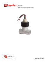
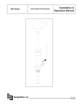
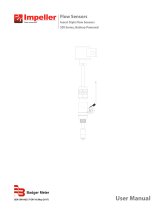
Badger Meter 250 Series Installation & Operation Manual

Type
Installation & Operation Manual

This manual is also suitable for

Installation &
Operation Manual
BadgerMeter, Inc.
Badger
®
Series
250 & 228
Flow Sensors
Metal Tee Type
Impeller Flow Sensors
872021
Rev. 6
4-09
2
"FM/CSA" Sensor
Designed for indoor or protected area applications where
intrinsic safety is required and the flow rates are between
0.5-30 feet/second and temperatures are below 221
deg. F. FM/CSA sensors are supplied with 20 feet of
2-conductor 20 AWG shielded U.L. type PTLC 105 deg.
C cable. These sensors must be used with an approved
safety barrier.
Models 228BR, 228CB, 228SS, and 228CS
Sizes of 2” and 2 1/2” are available in this series.
Model 228BR
This model consists of a Model 220BR sleeve and hex
mounting adapter assembly inserted in a 2" or 2 1/2"
bronze tee and preset to a specific height. The 2" size
includes copper solder adapters for mating to copper tub-
ing.
Model 228CB
This model consists of a Model 220BR sleeve and hex
mounting adapter assembly inserted in a 2" or 2 1/2"
Class 150 cast iron tee and preset to a specific height.
Model 228CS
This model consists of a Model 220SS sleeve and hex
mounting adapter assembly inserted in a 2" or 2 1/2"
Class 150 cast iron tee and preset to a specific height.
Model 228SS
This model consists of a Model 220SS sleeve and hex
mounting adapter assembly inserted in a 2" 316 stainless
steel tee and preset to a specific height.
Model 250BR
These models combine a PPS
electronics package
inserted in a 1/2”, 3/4", 1”, 1 1/4”, and 1 1/2” proprietary
cast bronze pipe tee with threaded NPT connections.
InTROdu CTIOn
Used in conjunction with any Badger Meter Impeller
flow monitor or transmitter, Badger Meter non-magnetic
flow sensors provide an accurate reading of the rate of
liquid flow as well as total accumulated flow. A number
of sensor models are offered, which cover applications
for a wide range of pipe sizes and pressure/temperature
specifications.
The flow sensors generate a frequency which is
proportional to flow rate. An internal preamplifier allows
the pulse signal to travel up to 2000 feet without further
amplification. Power to operate the sensor is provided
by the flow monitor. The impeller bearing assembly, shaft
and O-rings are replaceable in the field.
Badger Meter flow sensors feature a closed, six-
bladed impeller design, using a proprietary, non-magnetic
sensing technology. The forward-swept impeller shape
provides higher, more constant torque than four-bladed
impeller designs, and is less prone to fouling by water-
borne debris. The forward-curved shape, coupled
with the absence of magnetic drag, provides improved
operation and repeatability, even at lower flow rates. As
the liquid flow turns the impeller, a low impedance signal
is transmitted with a frequency proportional to the flow
rate.
Sensors of similar type are interchangeable, so there
is no need for recalibration after servicing or replacement.
Electronic Types
Badger Meter provides several basic sensor configura-
tions using the same impeller element. This allows for a
wide range of applications and pipe sizes. Sensors are
normally supplied with 20 feet of 2-conductor 20 AWG
shielded U.L. type PTLC 105 deg. C cable. Optional sen-
sors designated with the prefix "IR" feature two single
conductor 18 AWG solid copper wire leads 48 inches
in length with U.L. Style 116666 direct burial insulation.
These IR models are used in below grade applications
such as irrigation, municipal, and groundwater monitoring.
All Series 200 sensor electrical components are self-
contained. Pressure/temperature ratings for the various
models are contained in the Speciἀcations section of this
manual. These models can be further described as fol-
lows:
"Standard" Sensor
Designed for indoor or protected area applications such
as HVAC, pump control, and industrial process monitoring
where the flow rates are between 0.5-30 feet/second and
temperatures are below 221 deg. F. Standard sensors
are supplied with 20 feet of 2-conductor 20 AWG shielded
U.L. type PTLC 105 deg. C cable.
"IR" Sensor
Designed for below grade applications such as irrigation,
municipal, and groundwater monitoring where the flow
rates are between 0.5-30 feet/second and temperatures
are below 180 deg. F. IR sensors are supplied with two
single conductor, 18 AWG solid copper wire leads 48
inches in length with U.L. Style 116666 direct burial insu-
lation.
3
200 Series Metal Tee Sensors Matrix (½" to ")
Ex ample: 2xxxxx-xxxx
STYLE
Tee Mounted Insert Sensor ( 2" and 2.5" only)28
Cast Bronze Tee (1/2" to 1.5"only)50
MATERIAL
Brass/BronzeBR
Stainless Steel ( 2" and 2.5" only)SS
Tee - Carbon Steel Sensor BrassCB
Tee - Carbon Steel Sensor Stainless Steel CS
Si ze
0.5" 05
0.75" 07
1" 10
1.25" 12
1.5" 15
2" 20
2.5" 25
El ectronics Housing
PPS 0
ELECTRONICS
Magnetic2
FM/CSA Approved 4
Standard5
IR-Irrigation6
High Temperature8
O-RING
Viton 0
EPDM1
Buna N8
SHAFT
Zirconia Ceramic0
Hastalloy C1
Tungsten Carbide2
Titanium 3
Monel 5
316 Stainless Steel 6
Tantalum 7
IM PELLER
Nylon 1
Tefzel 2
BEARING
Pe nnlon 1
Tefzel 2
Teflon
3
Mechanical Installation
General
The accuracy of flow measurement for all flow measuring
devices is highly dependent on proper location of the
sensor in the piping system. Irregular flow velocity
profiles caused by valves, fittings, pipe bends, etc. can
lead to inaccurate overall flow rate indications even
though local flow velocity measurement may be accurate.
A sensor located in the pipe where it can be affected by
air bubbles, floating debris, or sediment may not achieve
full accuracy and could be damaged. Badger Meter flow
sensors are designed to operate reliably under adverse
conditions, but the following recommendations should be
followed to ensure maximum system accuracy:
1) Choose a location along the pipe where 10 pipe diam-
eters upstream and 5 pipe diameters downstream of
the sensor provide no flow disturbance. Pipe bends,
valves, other fittings, pipe enlargements and reduc-
tions should not be present in this length of pipe.
2) The preferred location for the sensor around the
circumference of a horizontal pipe is on top. If trapped
air or debris will interfere, then the sensor should be
located further around the pipe from the top but not
more than 45 degrees from top dead center. The
sensor should never be located at the bottom of the
pipe, as sediment may collect there. Locations
off top dead center cause the impeller friction to
increase, which may affect performance at low
flow rates. Any circumferential location is correct
for installation in vertical pipes. Rising flow
preferred to reduce effects of any trapped air.
Mechanical Installation for 228BR, 228CB,
228CS, and 228SS
These tee-type sensors have a factory set inser-
tion depth and alignment.
Warning: do not disturb the position of
thread hex adapter or the lower two nuts on
the threaded rods of the hex
adapter. This could lead to inaccurate calibra-
tion and faulty reading of the ἀow rate.
Remove sleeve assembly by removing the top
7/16" nuts only. Pull the sleeve assembly straight
out of the mounting adaptor.
To install the sensor tee
1) There must be free, unrestricted pipe for
at least 10 diameters upstream and 5 diameters
downstream of the tee. n ote: If soldering of
threaded adapters is to be done near the as-
sembly, remove the sensor sleeve to prevent
heat damage to O-rings and plastic parts.
2) Apply pipe compound over the first 3 or 4
threads of the mating pipe.
3) Thread the pipe into the sensor tee until
hand tight.
4) Tighten the pipe, using a wrench, an ad-
ditional 1 1/2 turns.
To install sensor in tee
1) Apply a small amount of silicone grease to O-rings on
sensor sleeve assembly and chamfer on inside lip of
tee. Clean off any grease which could be deposited
on the impeller.
2) Align flow arrow on sensor with direction of flow.
3) Carefully press sleeve straight into hex mounting
adaptor.
4) Install 7/16 lock nuts on threaded rod, tighten, do not
move bottom nuts as they set sensor depth.
5) Before pressurizing pipe, verify that:
• All threaded connections are tight.
The ow direction arrow on sensor is aligned with ow
direction.
The 7/16 nuts are re-installed on the threaded rods
above the metal collar.
Mechanical Installation for 250BR
Install with flow label pointing in the direction of flow
(downstream).
4
To install the sensor tee
1) Note intended direction of flow as indicated by
arrows on the cast bronze tee. There must be free,
unrestricted pipe for at least 10 diameters upstream
and 5 diameters downstream of the tee.
2) Apply pipe compound over the first 3 or 4 threads of
the mating pipe.
3) Thread the pipe into the sensor tee until hand tight.
4) Tighten the pipe, using a wrench, an additional 1 1/2
turns.
To install sensor in tee
1) Apply a small amount of silicone grease to O-rings on
sensor insert and chamfer on inside lip of tee. Clean
off any grease which could be deposited on the
impeller.
2) Align flow arrow on sensor with direction of flow.
3) Carefully press sensor straight into tee. Caution:
Impeller may strike sides of venturi cavity in tee if
misaligned, causing damage to impeller or shaft.
4) Install clevis pin through the tee, sensor, and conduit
cap, and install split ring.
5) Before pressurizing pipe, verify that:
a) All threaded connections are tight.
b) The flow direction arrows on the tee and
sensor are aligned with the flow direction.
c) The clevis pin and cotter ring are installed.
Electrical Installation "Standard" Sensors
1) The metal collar on the top of the Series 220 sensors
or an optional conduit cap on the Series 250 sensors
will accept 1/2" threaded conduit fittings.
2) Route the cable from the sensor to a Badger Meter
flow monitor/transmitter. The cable may be extended
up to 2000 feet, using 2-conductor shielded 20 AWG
or larger stranded copper wire. Be sure to leave
enough flexibility in the cable or conduit to allow for
future service of sensor, if necessary.
3) When connecting to a Badger Meter flow monitor/
transmitter, locate the section of terminal strip on the
monitor labeled “SEnSOR InPuT” or “SEnSOR”.
Connect the red wire to “ In, "SIGnAL(+)" or
"SIGnAL" terminal and the black wire to “Gnd ",
"SIGnAL(-)”, or "COM" terminal and the shield drain
wire (if applicable) to “SLd.
4) When interfacing with other equipment consult manu-
facture for input designations. The signal wave forms
and power requirements are as shown in the Specifi-
cations section. Refer to Technical Bulletin DTB-058
at www.badgermeter.com.
Electrical Installation "IR" sensors
The sensor leads are supplied with watertight caps over
the ends. See Application Note DAB-031 and Technical
Bulletin DTB-043 at www.badgermeter.com.
1) dO nOT remove the plastic caps from the sensor
leads until ready to splice.
2) Use a twisted pair cable suitable for direct burial to
connect the sensor to the transmitter, monitor, or con-
troller. Multi-pair telecommunication cable or direct
burial cables may be used.
3) Make a water tight splice. Two part epoxy type water-
proof kits are recommended. Be sure the epoxy seals
the ends of the cable jacket.
4) Make sure the epoxy is hardened before inverting the
splice or dropping it in standing water.
5) dO nOT make an underground splice unless abso-
lutely necessary.
6) Route the cable from the sensor to a Badger Meter
flow monitor/transmitter. The cable may be extended
up to 2000 feet, using 2-conductor shielded 20 AWG
or larger stranded copper wire with appropriate rat-
ings. Be sure to leave enough flexibility in the cable or
conduit to allow for future service of sensor, if neces-
sary.
7) When connecting to a Badger Meter flow monitor/
transmitter, locate the section of terminal strip on the
monitor labeled “SEnSOR InPuT” or “SEnSOR”.
Connect the red wire to “ In, "SIGnAL(+)" or
"SIGnAL" terminal and the black wire to “Gnd ",
"SIGnAL(-)”, or "COM" terminal and the shield drain
wire (if applicable) to “SLd.
8) When interfacing with other equipment, the signal
wave forms and power requirements are as shown in
the Specifications section. Refer to Technical Bulletin
DTB-058 at www.badgermeter.com.
Electrical Installation "High Temperature" sensors
1) Route a cable from the sensor to a Badger Meter flow
monitor/transmitter. The cable may be run up to 2000
feet, using 2-conductor shielded 20 AWG or larger
stranded copper wire. Be sure to leave enough flex-
ibility in the cable or conduit to allow for future service
of sensor, if necessary.
2) Connect to cable inside sensor electronic housing
and connect with standard wire nuts.
3) When connecting to a Badger Meter flow monitor or
transmitter, locate the section of terminal strip on the
monitor labeled “SEnSOR InPuT” or “SEnSOR”.
Connect the red wire to “ In, "SIGnAL(+)" or
"SIGnAL" terminal and the black wire to “Gnd ",
"SIGnAL(-)”, or "COM" terminal and the shield drain
wire (if applicable) to “SLd.
4) When interfacing with other equipment, the signal
wave forms and power requirements are as shown in
the specifications section.
Electrical Installation "Magnetic" sensors
The magnetic sensor has a custom wire connec-
tor that connects to the series 1400 monitor only.
The cable may be extended up to 100 feet from the
sensor. If extension cables are needed they may be
ordered from Badger Meter.
5
Electrical Installation (FM Sensors)
The Series 200 Sensor is approved, as an entity, as
Intrinsically Safe when installed in conformance with Bad-
ger Meter installation drawings 06-480-001 or 06-480-002
(samples shown on Page 7) as specified on the blue label
identifying an intrinsically safe sensor.
Entity approval implies that only the sensor is approved
as intrinsically safe. Unless power supplies, equipment,
and instruments connected to the sensor are each rated
either explosion-proof or intrinsically safe, these devices
cannot be installed in a hazardous area. The referenced
installation drawing shows such apparatus located in
a non-hazardous location. Proper interfacing between
the hazardous and non-hazardous areas must be pro-
vided. It is of absolute importance that this interface be
constructed and that all wiring be performed by qualified
contractors. To ensure the Intrinsic Safety of the instal-
lation, the connection of the intrinsically safe sensor to
instruments and or power supplies must take place using
an approved intrinsically safe barrier located in a non-
hazardous area. These barriers, listed below, are readily
available from various suppliers.
Manufacturer: Barrier:
Crouse-Hinds Spec 504 Cat No. SB19140M0715
Measurement Technology Ltd. MTL 715+ 15 V
R Stahl Intrinspak 9001/01-158-150-10
6
7
Calibration
Badger Meter sensors use unique K
and Offset numbers for calibration.
These numbers are derived from
calibration runs using NIST trace-
able instruments. Using both a K and
an Offset number provides higher
accuracy than using a K (pulse/gal)
factor alone. K and Offset numbers for
each tee configuration are listed in the
following tables.
Calibration Tables
The table on page 9 provides cali-
bration and operation data for Data
Industrial Metal Tee Sensors 0.5” to
2.5”.
Column 1 Tee Model Number
Column 2 Apparent I.D. - For use with the Series
900 and the Series 1000
Columns 3 and 4 The K value and Offset values to use
in our frequency equation:
This equation describes the frequency
of the output signal of all Badger
Meter flow sensors. By substituting
the appropriate K and Offset values
from the table, the sensor’s output
frequency can be calculated for each
pipe size. This information is required
when calibrating an output board or
when using the raw sensor data as
direct output to interface with a device
that is not a Badger Meter product.
Column 5 This column indicates the suggested
flow range of each tee sensor. Badger
Meter sensors will operate both
above and below the indicated flow
rates. However, good design practice
dictates the use of this range for best
performance.
Sensors should be sized for flow
rather than pipe size. To prevent
disturbances to the flow profile always
connect the sensor tee to pipe nipples
measuring at least 10 pipe diameters
in length on the up stream (supply)
side and at least 5 pipe diameters in
length on the downstream (delivery)
side before making the transition in
pipe size.
Calibration Table for
Series 228BR, 228CB, 250BR, 228CS, 228SS
Apparent I.D. Suggested
Model for Series K Offset Operating
1000, 900 ValueRange
(GPM)
228BR20xx-xxxx 1.99 2.747010-100
228BR25xx-xxxx 2.52 3.7410.386 16-160
228CB20xx-xxxx 2.07 2.8090.276 12-120
150 PSI Tee2.07
400 PSI Tee2.1 2.6040.2512-120
228CB25xx-xxxx 2.51 3.74 0.27716-160
228CS20xx-xxxx 2.07 2.8090.276 12-120
228SS20xx-xxxx 1.99 2.747010-100
250BR05xx-xxxx
sch40 PVC none0.3373790.0970410.8-8
sch80 PVC none0.3380730.1348540.8-8
sch40 steel none0.3562120.0757290.8-8
Type L none0.350899-0.3216660.8-8
250BR07xx-xxxx
sch40 PVC none0.4368270.5679151-10
sch80 PVC none0.43983 0.6923721-10
sch40 steel none0.4348360.7661961-10
Type L none0.4321270.6198131-10
250BR10xx-xxxx 1.05 0.3973680.2617682-40
250BR12xx-xxxx 1.38 0.764470.16489 3-60
250BR15xx-xxxx 1.61 1.065260.08924-80
Impeller Assembly and Shaft Replacement
If you are replacing an existing Badger Meter impeller or
shaft and have already calibrated your flow monitor/trans-
mitter, no calibration changes are necessary. For instal-
lation of a new flow monitor or for relocation of a sensor
in a new pipe size, please refer to the calibration instruc-
tions in flow monitor manual.
1) Depressurize pipe from which sensor is to be re-
moved.
2) If insert style (Models 228xx) remove the three lock
nuts that secure the positioning collar to the threaded
rods of metal sensor.
nOTE: Before removing lock nuts, record the dimen-
sion from top of 2” NPT adapter to the bottom of the
positioning collar. This dimension will be required
later to reinstall. For Series 250BR style remove the
clevis pin.
3) Remove the sensor from the hex adapter or the tee.
4) Note the impeller blade orientation relative to flow ar-
rows and the alignment hole in metal sensors beside
one of the sight holes. In order to maintain proper
calibration, the impeller will have to be reinstalled in
the same manner with the impeller blades pointing
toward the small alignment hole, and into the flow
direction as indicated by the flow arrows.
5) To remove the old impeller blade assembly, push the
old shaft out of the sleeve with the new shaft (or small
diameter rod) just far enough to grab the end with a
pair of pliers and pull the shaft completely out. The
impeller assembly will now be free, and will drop out.
6) Inspect the shaft and bearings for wear, and replace
as necessary.
7) Refer to Figure 1. To reinstall, position the impeller in
the cavity oriented as in Step 4 so that the impeller
blades point into the flow direction and toward the
small alignment hole located beside one of the sight-
8
ing holes on metal sensors. For 250B the flow direc-
tion arrow on the top of the sensor housing should
point downstream with the impeller blades pointing
upstream.
8) Carefully push the shaft through the sleeve and
impeller, taking care not to damage bearings. Make
sure that the shaft is inserted far enough so that it
clears the sleeve on each side of the impeller hous-
ing.
nOTE: If shaft is not carefully installed, the bearing
can be deformed, preventing free rotation.
9) Inspect the O-rings for damage and replace as
necessary. Clean the O-rings and the sleeve and lu-
bricate with silicone grease from the packet provided
or some other acceptable lubricant.
NOTE DIRECTION OF ARROW
USE PLIERS HERE
NOTE DIRECTION OF
IMPELLER
USE METAL PIN TO
REMOVE CERAMIC SHAFT
Figure 1
Impeller Assembly and Shaft Replacement
10) Install the sensor into the 2” NPT adapter or tee so
that alignment hole is facing upstream and flow ar-
rows point in the direction of the actual flow. Since
the positioning collar was not loosened during this
operation, the studs should all line up perfectly when
the sighting holes are parallel to pipe. If this has
been accidentally loosened, please refer to the instal-
lation instructions for the alignment of the flow sensor
unit.
11) Install and tighten the nuts or replace the clevis pin.
12) For metal sensors, double check that the distance
from the top of the 2” NPT adapter to the bottom
of the positioning collar equals the dimension as
measured in Step 2, and holes in sleeve sight exactly
down the pipe, the arrows point in direction of flow
and alignment holes located beside one sighting hole
is pointing towards the source. If not, refer to Installa-
tion section in this manual.
13) This completes the replacement procedure. The
system may now be repressurized and tested.
9
SpeciḀcations
Wetted Materials (except tees)
• See Ordering Matrix
Sensor Sleeve and Hex Adapter for 228BR, 228CB,
• Sleeve: Admiralty Brass, UNS C44300; Hex Adapt-
er: Valve Bronze, UNS C83600
Sensor Sleeve and Hex Adapter for 228SS and
228CS
• Series 300 Stainless Steel
Tee for 228B
• Cast Bronze, Class 125 Per ASME B16.15, and
Copper Coupling
Tee for 228SS
• Cast 316 Stainless, Class 150
Tee for 228CB and 228CS
• Cast Iron, Class 125 Per ASME B16.4
Tee for 250B
• Cast valve bronze, UNS C83600
Temperature Ratings
• Standard Electronics - 221 deg. F (105 deg. C)
• Irrigation Electronics - 150 deg. F (66 deg. C)
Pressure Ratings
At 100°F At 221°F
250BR 400 psi 325 psi
228B 200 psi 165 psi
228CB 175 psi 140 psi
220SS 400 psi 325 psi
Recommended design Flow Range
• 0.5 to 30 ft/sec for 228
• 0.3 to 15 ft/sec for 250B
Accuracy
• ± 1.0% of full scale over recommended design ow
range for 228
• ± 1.0% of rate for 250
Repeatability
• ± 0.3% of full scale over recommended design ow
range for all except 250B
• ± 0.7% of full scale over recommended design ow
range for 250B
Linearity
• ± 0.2% of full scale over recommended design ow
range for all except 250BR
• ± 0.7% of full scale over recommended design ow
range for 250BR
Transducer Excitation
• Quiescent current [email protected] to 35.0VDC
max.
• Quiescent voltage (V
high
)
Supply Voltage -(600uA*Supply impedance)
• ON state (V
Low
) Max. 1.2VDC@40mA current limit
(15ohm+0.7VDC)
Output Frequency
• 3.2 Hz to 200 Hz for all except 250BR
• 0.8 Hz to 80 Hz for 250BR
Output Pulse Width
• 5 msec ±25%
• Square wave between 100Hz to 200Hz limit
Electrical Cable for Standard Sensor Electronics
• 20 feet of 2-conductor 20 AWG shielded U.L. type
PTLC wire provided for connection to display or
analog transmitter unit. Rated to 105 deg. C. May
be extended to a maximum of 2000 feet with similar
cable and insulation appropriate for application.
Electrical Cable for IR Sensor Electronics
• 48 inches of U.L. Style 116666 copper solid AWG
18 wire with direct burial insulation. Rated to 105
deg. C.
10
Troubleshooting
1) If the voltage at the sensor input is less than 7.0
VDC in a no flow situation, disconnect the sensor
from the barrier strip and measure the voltage at
the sensor input terminals of the barrier strip again.
It should be between 8.0 VDC and 20.0 VDC. If the
voltage at the sensor input is still below 7.0 VDC
or 3.0 VDC, the problem may be with the monitor.
(hardware or programming)
2) If you suspect that the sensor is bad, you can test
the monitor circuitry by connecting a piece of wire
to one of the sensor input terminals and tap the
other side of the wire to the other sensor input
terminal. Shorting across the sensor input termi-
nals ON and OFF repeatedly allows the display to
respond by trying to calculate a flow rate for the
frequency of your shorting action. If the display
does not show a change from 0.00, it indicates a
problem with the monitor.
3) If the monitor tests ok and there are any splices in
the cable, break the sensor cable at the splice clos-
est to the sensor and retry the shorting test in step
2.
4) If the cable tests ok, drain the pipe line, verify the
pressure is off, and pill the clevis pin for Series 250
or remove top lock nuts for Series 228 holding the
sensor electronics. Spin the impeller by hand. If
flows are noted on the display, and impeller spins
freely then the flow rates may have been below
our design minimums or the line was full of air. Try
again. If the sensor fails to respond then replace
sensor.
11
(This page intentionally left blank.)
Due to continuous research, product improvements and enhancements, Badger
Meter reserves the right to change product or system specifications without notice,
except to the extent an outstanding contractual obligation exists.
BadgerMeter, Inc.
Copyright © Badger Meter, Inc. 2009. All rights reserved.
Badger
®
and Data Industrial
®
are registered trademarks of Badger Meter, Inc.
(This page intentionally left blank.)
  • Page 1 1
  • Page 2 2
  • Page 3 3
  • Page 4 4
  • Page 5 5
  • Page 6 6
  • Page 7 7
  • Page 8 8
  • Page 9 9
  • Page 10 10
  • Page 11 11
  • Page 12 12

Badger Meter 250 Series Installation & Operation Manual

Type
Installation & Operation Manual
This manual is also suitable for

Ask a question and I''ll find the answer in the document

Finding information in a document is now easier with AI