Page is loading ...

Flow Sensors
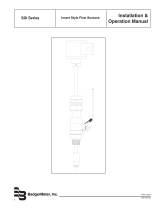
Insert Style Flow Sensors
SDI Series, Battery Powered
SEN-UM-00217-EN-10 (May 2017)
User Manual

Flow Sensors, Insert Style Flow Sensors, SDI Series, Battery Powered
Page ii May 2017SEN-UM-00217-EN-10

CONTENTS
Introduction. . . . . . . . . . . . . . . . . . . . . . . . . . . . . . . . . . . . . . . . . . . . . . . . . . . . . . . . . . . . . . . . . . . . . . . . . 5
Models Available. . . . . . . . . . . . . . . . . . . . . . . . . . . . . . . . . . . . . . . . . . . . . . . . . . . . . . . . . . . . . . . . . . . . . . 5
Electronic Outputs. . . . . . . . . . . . . . . . . . . . . . . . . . . . . . . . . . . . . . . . . . . . . . . . . . . . . . . . . . . . . . . . . . . . . 5
Scaled Pulse Output. . . . . . . . . . . . . . . . . . . . . . . . . . . . . . . . . . . . . . . . . . . . . . . . . . . . . . . . . . . . . . . . . 5
Battery Powered Ordering Matrix . . . . . . . . . . . . . . . . . . . . . . . . . . . . . . . . . . . . . . . . . . . . . . . . . . . . . . . . 6
Display Options. . . . . . . . . . . . . . . . . . . . . . . . . . . . . . . . . . . . . . . . . . . . . . . . . . . . . . . . . . . . . . . . . . . . 6
Mechanical Installation. . . . . . . . . . . . . . . . . . . . . . . . . . . . . . . . . . . . . . . . . . . . . . . . . . . . . . . . . . . . . . . . . . 7
Installation for Direct Insert Models . . . . . . . . . . . . . . . . . . . . . . . . . . . . . . . . . . . . . . . . . . . . . . . . . . . . . . . 8
Installation for Hot Tap models . . . . . . . . . . . . . . . . . . . . . . . . . . . . . . . . . . . . . . . . . . . . . . . . . . . . . . . . . 10
Programming . . . . . . . . . . . . . . . . . . . . . . . . . . . . . . . . . . . . . . . . . . . . . . . . . . . . . . . . . . . . . . . . . . . . . . . 15
Customer Reference Number Tables . . . . . . . . . . . . . . . . . . . . . . . . . . . . . . . . . . . . . . . . . . . . . . . . . . . . . . . . 17
K & Oset Tables . . . . . . . . . . . . . . . . . . . . . . . . . . . . . . . . . . . . . . . . . . . . . . . . . . . . . . . . . . . . . . . . . . . . . 20
Specications . . . . . . . . . . . . . . . . . . . . . . . . . . . . . . . . . . . . . . . . . . . . . . . . . . . . . . . . . . . . . . . . . . . . . . . 22
Power Specications . . . . . . . . . . . . . . . . . . . . . . . . . . . . . . . . . . . . . . . . . . . . . . . . . . . . . . . . . . . . . . . 23
User Manual
Page iii May 2017 SEN-UM-00217-EN-10

Flow Sensors, Insert Style Flow Sensors, SDI Series, Battery Powered
Page iv May 2017SEN-UM-00217-EN-10

INTRODUCTION
The Data Industrial® SDI Series impeller flow sensor offers unparalleled performance for liquid flow measurement in closed
pipe systems in an easy to install economical package. Impeller sensors offer a quick response to changes in flow rate and
are well suited to flow control and batch type applications in addition to flow monitoring. The four-bladed impeller design is
rugged, non-fouling and does not require custom calibration.
Coupled with the proprietary patented digital detection circuit, the sensor measures flows from 1.0 fps to over 20 fps,
regardless of the conductivity or turbidity of the liquid.
The battery powered versions are a complete flow measuring system providing a programmable display of rate, total or both
powered by a “C” sized lithium battery. Options include a scalable pulse output and a data logger.
MODELS AVAILABLE
Direct insert sensor models are installed in piping configurations that are not in service or under pressure.
Hot tap insert sensor models feature isolation valves and mounting hardware to install or remove the sensor from a pipeline
that would be difficult to shut down or drain. In a true “hot tap” installation the sensor is mounted in the pipe under pressure
by attaching a service saddle or weld-on fitting to the pipe and mounting the isolating valve and nipple to the threaded
connection. A hole is then cut in the wall of the pipe through the valve using a commercial tapping machine with a
1 in. (25 mm) size shell cutter. Once the hole is cut, the tapping machine is removed and the valve is shut. Then the sensor
assembly is mounted to the isolation valve and extended into the pipeline to measure flow.
Even in new construction a hot tap sensor may be appropriate for service considerations.
The small stem diameter allows the sensor to be inserted into the pressurized pipeline by hand without the need for an
installation tool. The mounting hardware holds the sensor firmly in place at the correct depth and alignment.
ELECTRONIC OUTPUTS
Scaled Pulse Output
The scaled pulse is produced by an onboard micro-controller for precise, accurate outputs. This option may be programmed
to produce a solid state contact closure scaled to any number of engineering units of measure. Sensors may be
preprogrammed at the factory or field programmed using the ASDIB-20 SDI programming kit and Windows
®
-based software
program. All information is stored in the flow sensor non-volatile memory.
Introduction
Page 5 May 2017 SEN-UM-00217-EN-10

Battery Powered Flow Sensors Ordering Matrix
SDI 0 D1 B N 1 - 0 2 0 0
MATERIAL
Stainless Steel / PPS Tip 0
Brass / PPS Tip (not available with hot tap) 1
Stainless Steel / PEEK Tip 2
TYPE
Direct Insert for Pipe 1-1/2" thru 10" * D1
Direct Insert for Pipe 12" thru 36" * D2
Direct Insert 36" and UP* D3
Hot Tap for Pipe 1-1/2" thru 10" * H1
Hot Tap for Pipe 12" thru 36" * H2
Hot Tap for Pipe 36" and UP * H3
ELECTRONIC HOUSING
Battery Powered/NEMA 6 B
OUTPUT
No Output N
Scaled Pulse 2
2 Pulse Output 9
DISPLAY
LCD Option 1
Remote Display/NEMA 4X 2
O-RING
Viton® 0
EPDM 1
AFLAS 2
SHAFT
2Tungsten Carbide [Standard]
Hastelloy
®
C-276 [optional - consult factory]
1
IMPELLER
Stainless Steel 0
BEARING
Torlon
®
0
Figure 1: Battery operated ordering matrix
* Pipe size for reference only. Depending on pipe size, tapping saddle or existing hardware, longer sensor length may be required. Consult the factory. For
material details, consult the factory.
Display Options
The eight character 3/8 in. LCD is mounted on the sensor, visible through a lens at the top of the electronics housing.
An optional remote display is available where the LCD is located in a wall mount NEMA 4X enclosure. The remote may be
connected to the flow sensor up to a maximum of 50 feet (15 m) away using extension cables.
Cable Length Part Number
5 ft extension cable 07101
10 ft extension cable 07108
20 ft extension cable 07102
50 ft extension cable 07109
Table 1: SDI remote cable part numbers
Electronic Outputs
Page 6 May 2017SEN-UM-00217-EN-10

MECHANICAL INSTALLATION
The accuracy of flow measurement for all insert type flow measuring devices is highly dependent on proper location of the
sensor in the piping system. Irregular flow velocity profiles caused by valves, fittings, and pipe bends, can lead to inaccurate
overall flow rate indications even though local flow velocity measurement may be accurate. A sensor located in the pipe that
is partially full or where it can be affected by air bubbles, floating debris, or sediment may not achieve full accuracy and could
be damaged.
Data Industrial flow sensors are designed to operate reliably under adverse conditions, but the following recommendations
should be followed to ensure maximum system accuracy:
5 x Pipe Dia
DATA INDUSTRIAL
SDI Series Sensor
10 x Pipe Dia
FLOW
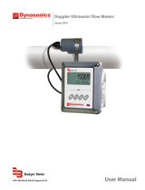
Figure 2: Minimum recommended straight run distance
1. Choose a location along the pipe where there is straight pipe for a distance of ten pipe diameters upstream and ve pipe
diameters downstream of the sensor. Pipe bends, valves, other ttings, pipe enlargements and reductions or anything else
that would cause a ow disturbance should not be present in this length of pipe.
2. The recommended tap location around the circumference of a horizontal pipe is on top. If trapped air or debris will
interfere, then the sensor should be located around the pipe from the top preferably not more than 45 degrees from
top dead center. The sensor should never be located at the bottom of the pipe, as sediment may collect there. Locations
o top dead center cause the impeller friction to increase, which may aect performance at low ow rates. Any
circumferential location is correct for installation in vertical pipes.
3. Insertion depth is critical to accuracy. The algorithm used to convert impeller motion into ow was developed through
ow tests in an independent calibration laboratory. The impeller must be located in the same position in the pipe as it
was in the calibration test for the impeller frequency to accurately describe the same liquid velocity. Detailed installation
instructions on the following pages include methods for ensuring correct insertion depth.
4. Alignment of the sensor is also important. The impeller shaft must be perpendicular to the ow for accuracy. Alignment
instructions are also included on the following pages.
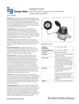
D1=15 3/4”
D2=19”
4.23”
0.660”
Handtight Engagement + Wrench
Makeup
Per ANSI/ASME B1.20.1-1993, R1992
D1 is for pipe sizes 1½” - 10” *
D2 is for pipe sizes 12” - 36” *
*Pipe sizes are for reference only - Depending on pipe material, tapping
saddle, or existing hardware a longer sensor length may be required,
Consult Factory.
Figure 3: Direct insertion sensor dimensions
Mechanical Installation
Page 7 May 2017 SEN-UM-00217-EN-10

Installation for Direct Insert Models
These instructions are for the installation of flow sensors into piping systems that are not under pressure at the time of
installation. If the line must be tapped under pressure, a hot tap style sensor must be used. See the following section for hot
tap installation instructions.
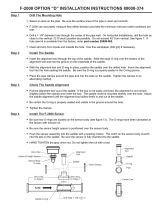
Mounting
Adaptor
Stem
Stem Collar
Hex Cap
Cover
Pipe Saddle
(ref.)
Gasket
(ref)
O-Ring
O-Ring
Groove
O-Ring
Expanded View
Figure 4: Installation for direct insert model
The insertion depth and alignment of the sensor are critical to the accuracy of the flow measurement. The impeller must be at
the same location in the pipe as it was during calibration. Badger
Meter provides sensors with different stem lengths. Longer
stems are intended for use in larger diameter pipes and shorter stems for use in smaller pipelines. However, stem length has
no affect on the operation of the sensor provided that the impeller is positioned correctly in the pipe.
Direct insert models are available in stem lengths designated D1 and D2. The D1 is intended for nominal pipe diameters from
1-1/2…10 in. (38…254 mm), and the D2 for pipe diameters from 12…36 in. (30…91 cm). However, pipe with extra thick walls,
existing linings, or unusual tapping hardware may require longer length sensors. For these pipes, consult the factory. For
larger pipe sizes, hot tap style sensors equipped with an isolation valves are recommended.
The preferred method of installation is by means of a saddle with 1 in. NPT outlet. On steel pipelines a weld-on type tting
may be substituted.
1. Attach the saddle to a section of pipe that has at least 10 diameters of straight pipe ahead and ve diameters of straight
pipe behind the saddle. Drill a minimum 1-1/8 in. (29 mm) diameter hole in the pipe.
2. Remove the sensor assembly from the mounting hardware by loosening the hex cap over the stem collar and the cover to
the mounting adapter and detaching the assembly. Set aside taking care not to damage impeller/shaft assembly.
3. Attach the pipe thread end of the mounting adapter to the saddle or weld-o-let using a pipe joint compound and tighten
the joint. Do not apply sealing compound to the top thread of the mounting adapter, it is sealed with an O-ring.
Mechanical Installation
Page 8 May 2017SEN-UM-00217-EN-10

Pipe
Saddle
(ref.)
Mounting
Adapter
Gasket
(ref)
4. Locate the sensor rotor assembly a xed distance from the center of the
pipe. To position the impeller at this depth, a reference measurement for
the pipe size and schedule is used.
a. Look up the pipe size and schedule number in the “Customer Reference
Number Tables” on page 17 and note the Customer Reference
Number (Customer Ref #).
OTE:N The Customer Reference Number is calculated using the following
formula:
Ref # = Insertion Depth + Wall Thickness + Cover Thickness (0.875 in.
(22 mm))
b. Next, measure from the outside wall of the pipe to the top of the
installed mounting adapter. This is dimension “B” in Figure 5.
c. Add this number to the reference measurement. The resulting number
is dimension “C” in Figure 5.
Dimension “C” = Customer Ref # + Dimension “B”
d. Dimension “C” is the distance from the recess of the sensor tip to the
bottom of the stem collar. Insert the metal tab of a tape measure into
the recess of the flow sensor tip. Extend the tape up the stem and mark
the shaft with a pencil.
e. Slide the collar along the shaft until its bottom surface is at the mark
on the stem. Tighten the cap screw on the collar. When the sensor is
reassembled, this will set the insertion depth of the sensor.
5. Attach the sensor to the mounting adapter by gently pushing the ow
sensor into the mounting adapter until the cover touches the mounting
adapter. Tighten the cover against the O-ring seal. This will seal the
sensor assembly.
6. Continue to insert the ow sensor stem until the stem collar meets the
cover. Thread the hex cap onto the mounting adapter but do not tighten.
7. Align the ow sensor with the pipe by using the at cover on the
electronics housing as a guide. Place a straightedge along the cover and
rotate the sensor until the straightedge is parallel with the pipe as shown
in Figure 6.
8. Tighten the hex cap over the collar approximately 10 ft-lb. The hex cap
holds the sensor alignment but performs no sealing functions.
DO NOT OVER TIGHTEN
9. Pressurize the pipeline and check for leaks.
Pipe Saddl
e
(ref.)
Mounting
Adapter
Gasket
(ref)
Stem
Stem Collar
Hex Cap
Cover
Figure 5: Dimensions "B" and "C"
Straight Edge Parallel to Pipe
Pipe Pipe
SDI
Flow Sensor
Figure 6: Level the sensor
Mechanical Installation
Page 9 May 2017 SEN-UM-00217-EN-10

Installation for Hot Tap Models
Expanded View
O-Ring
O-Ring
Groove
Stem
Hex Cap
Cover
Stem Collar
Ball Valve
1” MNPT
Thread
The insertion depth and alignment of the sensor are critical to the
accuracy of the flow measurement. The impeller must be at the
same location in the pipe as it was during calibration. Badger
Meter
provides sensors with three different stem lengths. Longer stems
are intended for use in larger diameter pipes and shorter stems for
use in smaller pipelines. However stem length has no affect on the
operation of the sensor provided that the impeller is positioned
correctly in the center of the pipe.
In Figure 8, stem length H1 is intended for use in nominal pipe
diameters from 1-1/2…10 in. (38…254 mm), H2 is for nominal pipe
diameters from 12…36 in. (30…91 cm), and stem length H3 is for
nominal pipe diameters from 36 in. and up. However, pipe with extra
thick walls, existing linings, or unusual tapping hardware may require
longer length sensors. For these pipe types, consult the factory.
The preferred method of installation is by means of a saddle with
1 in. NPT outlet. On steel pipelines a weld-on type fitting may be
substituted.
1. Attach the saddle to a section of pipe that has at least
10 diameters of straight pipe ahead and 5 diameters of straight
pipe behind the saddle. Drill a minimum 1-1/8 in. (29 mm)
diameter hole in the pipe.
2. Remove the sensor assembly from the mounting hardware by
loosening the hex cap over the stem collar and the cover to the
mounting adapter and detaching the assembly. Set aside taking
care not to damage the impeller/shaft assembly.
Figure 7: Installation for hot tap models
Mechanical Installation
Page 10 May 2017SEN-UM-00217-EN-10

H1=19” *
H2=21½” *
H3=27½” *
7.85”
7 ¾”
2 27/32”
4 11/32”
* Pipe Sizes for reference only - Depending on pipe material, tapping
saddle, or existing hardware longer sensor length may be required -
Contact Factory.
Figure 8: Hot tap sensor dimensions
3. If the pipe is drained, drill a 1-1/8 in. (29 mm) minimum hole into the pipe and install a saddle or welded tting onto the
pipe. If the pipe is under pressure, a tapping machine will be needed. Install the saddle onto the pipe and thread the
1 in. NPT end of the valve into the saddle using pipe joint compound.
4. Attach the tapping adapter, (Badger Meter/Data Industrial Part# A-1027) to the top of the valve (make sure O-ring is
properly seated in the O-ring groove in the top of the ball valve assembly). It is recommended at this point that you open
the valve and connect the A-1027 to a water or AIR Source to pressure test the saddle and valve-threaded joint. Once the
pipe is drilled, any leaks in this area would require that the pipe be drained to repair.
5. Use any tapping machine with a 1 in. MNPT pipe thread, with an arbor less than 1 in. O.D., capable of holding a 1.00 in.
Hole Saw, and with at least 7 in. of travel. The SDI ball valve is manufactured oversized with a 1.00 in. bore, and the SDI
sensor is almost interference t requiring that the hole being drilled also be 1.00 in. For this reason, the 7/8 in. drill bit
normally recommended for drilling through a 1 in. ball valve cannot be used.
6. Attach the tapping machine to the tapping adapter. Ensure that all connections and seals are tight.
7. Slowly open the valve by rotating the handle 90° and lower the cutter past the valve ball to the pipe. Drill the 1 in. nominal
hole according to the manufacturer’s instructions.
8. Withdraw the cutter past the valve ball, close the valve and remove the tapping tool.
9. Remove the Data Industrial tapping adapter from the top of the valve.
10. The sensor rotor assembly is to be located a xed distance from the center of the pipe. To position the impeller at this
depth, a reference measurement for the pipe size and schedule is used.
a. Look up the pipe size and schedule number in the “Customer Reference Number Tables” on page 17 and note the
Customer Reference Number (Customer Ref #).
OTE:N The Customer Reference Number is calculated using the following formula:
Ref # = Insertion Depth + Wall Thickness + Cover Thickness (0.875 in. (22 mm))
b. Next, measure from the outside wall of the pipe to the top of the installed mounting adapter. This is dimension “B” in
Figure 5 on page 9.
c. Add this number to the reference measurement. The resulting number is dimension “C” in Figure 5 on page 9
Dimension “C” = Customer Ref # + Dimension “B”
d. Dimension “C” is the distance from the recess of the sensor tip to the bottom of the stem collar. Insert the metal tab of a
tape measure into the recess of the flow sensor tip. Extend the tape up the stem and mark the shaft with a pencil.
Mechanical Installation
Page 11 May 2017 SEN-UM-00217-EN-10

Pipe Saddle
(ref.)
Gasket
(ref)
Ball
Valve
e. Slide the collar along the shaft until its bottom surface is at the mark on the stem.
Tighten the cap screw on the collar. When the sensor is reassembled, this will set the
insertion depth of the sensor. Make sure to hold the sensor up tight against the cover
when installing it onto the valve, to prevent the possibility of damaging the impeller
by striking the closed ball of the valve.
11. Slide the cover down the stem until it stops.
12. Attach the sensor to the valve by inserting the impeller end of the stem into the valve
until the cover touches the top of the valve. The sensor tip and impeller will be in the
section of the valve above the ball.
13. Tighten the cover against the O-ring in the top of the valve. This will seal the
sensor assembly.
14. Open the ball valve again by slowly rotating the handle 90°. If the cover was not at the
bottom of the sensor stem, water pressure from the pipe would now push it out until it
stops. However, the sensor cannot be ejected from the pipe if the cover is secured to the
valve. Check to make sure all joints are tight.
15. Insert the ow sensor stem into the pipe by pushing against the top of the electronics
housing with a slight twisting motion until the stem collar meets the cover. The force
required to push the sensor into the pipeline is approximately 20% of the line pressure.
Be aware of the close spacing between the diameter of the ow sensor, the bore of
the ball valve and the hole in the pipe. If the sensor stops or “catches” before the stem
collar meets the cover, apply a gentle rocking/twisting motion to the sensor to continue
its travel.
16. While holding the ow sensor collar against the cover, thread the hex cap onto the cover
to hold the ow sensor in place, but do not tighten.
17. Align the ow sensor with the pipe by using the at side cover of the electronics
housing as a guide. Place a straightedge along the cover and rotate the sensor until the
straightedge is parallel to the pipe as shown in Figure 10.
18. Tighten the hex cap to the cover to approximately 10 ft-lb. The hex cap holds the sensor
alignment and depth but performs no sealing functions. DO NOT OVER TIGHTEN.
19. Pressurize the pipeline and check for leaks.
Pipe Saddle
(ref.)
Gasket
(ref)
Ball
Valve
Stem Colla
r
Stem
Hex Cap
Cover
Figure 9: Sensor tip and stem collar
Straight Edge Parallel to Pipe
Pipe Pipe
SDI
Flow Sensor
Figure 10: Level the sensor
Mechanical Installation
Page 12 May 2017SEN-UM-00217-EN-10

Removing the Side Cover
Figure 11
Side Cover Screws
There are 6 screws to remove from the side cover / battery holder. To remove the side
cover, use a screwdriver to unscrew each cover screw counterclockwise. These screws
are captive so they will not fall out of the cover. Use care when replacing the side cover
to insure the O-ring is in place.
DO NOT REMOVE CIRCULAR COVER from top of sensor. You may disturb the seal and
label alignment.
Figure 11: Remove the side cover
Battery Replacement – Local Display Option
Power Connector
(Attach DI 3V Lithium only)
Programming socket
(for DI A303 Programming cable only
)
Open collector pulse output
Although the Battery Powered SDI has up to a 5 year
battery life, there will be a time when the battery
needs to be replaced.
The battery is inside the blue housing on the end
of the flow sensor, accessible by removing the side
cover / battery holder. The battery is held in a spring
clip attached to the cover. The required battery is a
3V lithium “C” size that can be purchased through
Badger Meter.
The battery supplied by Badger Meter has the
connector required to plug it into the power header.
See Figure 12 for the power header location.
Figure 12: Battery replacement, local display
Battery Replacement – Remote Display Option
Power Connector
(Attach DI 3V Lithium only)
Programming socket
(for DI A303 Programming cable only
)
Open collector pulse output
The battery is located inside the remote display
housing. Loosen the 1/4 turn fasteners at the corners
of the cover. Open the enclosure to locate the “C” size
lithium battery held by a spring clip. Disconnect the
battery from the header and remove battery from the
clip. Reverse this procedure to install a new battery.
See Figure 13 for the power header location.
Figure 13: Battery replacement, remote display
Mechanical Installation
Page 13 May 2017 SEN-UM-00217-EN-10

Wiring Pulse Output
The optional pulse output of the Battery Powered SDI is a scaled pulse output that is set in the programming software. The
output type is an open collector transistor closure with a maximum sinking current of 100 mA.
The cable that plugs into the existing pigtail from the PC board is PN 807021.
Power Connector
(Attach DI 3V Lithium only)
Programming socket
(for DI A303 Programming cable only
)
Open collector pulse output
Figure 14: Pulse output
Programming
Page 14 May 2017SEN-UM-00217-EN-10

PROGRAMMING
To program Badger Meter SDI Series sensors, install the Data Industrial programming software on a computer and enter data
in the templates of the Windows
®
based program following these steps.
1. Load the interface software onto the computer.
2. Connect the PC to the SDI with the ASDIB-20 SDI programming kit. Plug in the RJ11 plug from the ASDIB-20 kit to the RJ11
socket on Battery Powered SDI. Connect the DB9 connector of the ASDIB-20 kit to the PC COMM port of a PC that has the
SDI software installed.
3. Open the interface software.
4. Select Conguration in the menu and select the appropriate COMM PORT.
5. Select Parameters to open the Parameters screen.
Programming
Page 15 May 2017 SEN-UM-00217-EN-10

6. Program the parameters using the following screens as reference.
OTE #1N After you press Send, the status bar shows programming progress. It may take up to 1-1/2 minutes to program the
Battery Powered SDI. When the status bar says “updated”, the Battery Powered SDI is programmed.
OTE #2N After you press Exit, it takes about 10 seconds to go back to the operating display and refresh the Flow Rate and
Flow Total.
Programming
Page 16 May 2017SEN-UM-00217-EN-10

CUSTOMER REFERENCE NUMBER TABLES
Table A1 – Customer Reference Number
Pipe Pipe Schedules
Size O.D. Description 10 10s 40 40s/Std 80 SDR21
1-1/2 in. 1.900
Wall
Insertion Depth
Customer Ref #
0.109
0.58
1-9/16
0.109
0.58
1-9/16
0.145
0.54
1-9/16
0.145
0.54
1-9/16
0.200
0.49
1-9/16
—
2 in. 2.375
Wall
Insertion Depth
Customer Ref #
0.109
0.81
1-13/16
0.109
0.81
1-13/16
0.154
0.77
1-13/16
0.154
0.77
1-13/16
0.218
0.71
1-13/16
0.113
0.81
1-13/16
2-1/2 in. 2.875
Wall
Insertion Depth
Customer Ref #
0.120
1.05
2-1/16
0.120
1.05
2-1/16
0.203
0.97
2-1/16
0.203
0.97
2-1/16
0.276
0.90
2-1/16
0.137
1.04
2-1/16
3 in. 3.500
Wall
Insertion Depth
Customer Ref #
0.120
1.37
2-3/8
0.120
1.37
2-3/8
0.216
1.27
2-3/8
0.216
1.27
2-3/8
0.300
1.19
2-3/8
0.167
1.32
2-3/8
4 in. 4.500
Wall
Insertion Depth
Customer Ref #
0.120
1.70
2-11/16
0.120
1.70
2-11/16
0.237
1.61
2-23/32
0.237
1.61
2-23/32
0.337
1.53
2-3/4
0.214
1.63
3-1/8
5 in. 5.563
Wall
Insertion Depth
Customer Ref #
0.134
1.59
2-5/8
0.134
1.59
2-5/8
0.258
1.51
2-21/32
0.258
1.51
2-21/32
0.375
1.44
2-11/16
—
6 in. 6.625
Wall
Insertion Depth
Customer Ref #
0.134
1.91
2-29/32
0.134
1.91
2-29/32
0.280
1.82
2-31/32
0.280
1.82
2-31/32
0.432
1.73
3-1/32
0.316
1.83
3-1/32
8 in. 8.625
Wall
Insertion Depth
Customer Ref #
0.148
2.50
3-17/32
0.148
2.50
3-17/32
0.322
2.39
3-19/32
0.322
2.39
3-19/32
0.500
2.29
3-21/32
0.410
2.40
3-11/16
10 in. 10.750
Wall
Insertion Depth
Customer Ref #
0.165
3.13
4-5/32
0.165
3.13
4-5/32
0.365
3.01
4-1/4
0.365
3.01
4-1/4
0.594
2.87
4-11/32
0.511
2.98
4-3/8
12 in. 12.750
Wall
Insertion Depth
Customer Ref #
0.180
3.72
4-25/32
0.180
3.72
4-25/32
0.406
3.58
4-7/8
0.375
3.60
4-27/32
0.688
3.41
5
0.606
3.52
5
14 in. 14.000
Wall
Insertion Depth
Customer Ref #
0.250
2.03
3-5/32
0.188
2.04
3-3/32
0.438
1.97
3-9/32
0.375
1.99
3-1/4
0.750
1.88
3-1/2
—
16" 16.000
Wall
Insertion Depth
Customer Ref #
0.250
2.33
3-7/16
0.188
2.34
3-13/32
0.500
2.25
3-5/8
0.375
2.29
3-17/32
0.844
2.15
3-7/8
—
18 in. 18.000
Wall
Insertion Depth
Customer Ref #
0.250
2.63
3-3/4
0.188
2.64
3-23/32
0.562
2.53
3-31/32
0.375
2.59
3-27/32
0.938
2.42
4-1/4
—
20 in. 20.000
Wall
Insertion Depth
Customer Ref #
0.250
2.93
4-1/16
0.218
2.94
4-1/32
0.594
2.82
4-9/32
0.375
2.89
4-1/8
1.031
2.69
4-19/32
—
22 in. 22.000
Wall
Insertion Depth
Customer Ref #
0.250
3.23
4-11/32
— —
0.375
3.19
4-7/16
1.125
2.96
4-31/32
—
For sizes above 30", consult factory. Pipe O.D. & Schedule, or pipe O.D. & I.D., or pipe O.D. & wall thickness is required.
A blank cell ( — ) = No data at time of printing.
Customer Reference Number Tables
Page 17 May 2017 SEN-UM-00217-EN-10

Table A1 – Customer Reference Number
Pipe Pipe Schedules
Size O.D. Description 10 10s 40 40s/Std 80 SDR21
24 in. 24.000
Wall
Insertion Depth
Customer Ref #
0.250
3.53
4-21/32
0.250
3.53
4-21/32
0.688
3.39
4-31/32
0.375
3.49
4-3/4
1.219
3.23
5-5/16
—
26 in. 26.000
Wall
Insertion Depth
Customer Ref #
—
0.312
3.81
5
—
0.375
3.79
5-1/32
— —
28 in. 28.000
Wall
Insertion Depth
Customer Ref #
—
0.312
4.11
5-9/32
—
0.375
4.09
5-11/32
— —
30 in. 30.000
Wall
Insertion Depth
Customer Ref #
0.312
4.41
5-19/32
0.312
4.41
5-19/32
—
0.375
4.39
5-5/8
— —
For sizes above 30", consult factory. Pipe O.D. & Schedule, or pipe O.D. & I.D., or pipe O.D. & wall thickness is required.
A blank cell ( — ) = No data at time of printing.
Table A2 – Customer Reference Number
Copper Tube Type
Size O.D. Description K L M DWV
1-1/2 in. 1.625
Wall
Insertion Depth
Customer Ref #
0.072
0.48
1-7/16
0.060
0.49
1-7/16
0.049
0.50
1-7/16
0.042
0.51
1-7/16
2 in. 2.125
Wall
Insertion Depth
Customer Ref #
0.083
0.72
1-11/16
0.070
0.73
1-11/16
0.058
0.74
1-11/16
0.042
0.76
1-11/16
2-1/2 in. 2.625
Wall
Insertion Depth
Customer Ref #
0.095
0.95
1-29/32
0.080
0.97
1-29/32
0.065
0.98
1-29/32
—
3 in. 3.125
Wall
Insertion Depth
Customer Ref #
0.109
1.19
2-3/16
0.090
1.21
2-3/16
0.072
1.23
2-3/16
0.045
1.25
2-3/16
4 in. 4.125
Wall
Insertion Depth
Customer Ref #
0.134
1.54
2-9/16
0.110
1.56
2-9/16
0.095
1.57
2-17/32
0.058
1.60
2-17/32
6 in. 6.125
Wall
Insertion Depth
Customer Ref #
0.192
1.72
2-25/32
0.140
1.75
2-3/4
0.122
1.76
2-3/4
0.083
1.79
2-3/4
A blank cell ( — ) = No data at time of printing.
Table A3 – Customer Reference Number
Ductile Iron Because of the variety of iron pipe classes, sizes, and wall thicknesses, consult the
factory for customer reference number. Pipe O.D. & Schedule, or pipe O.D. & I.D., or Pipe
O.D. and wall thickness is required.
Customer Reference Number Tables
Page 18 May 2017SEN-UM-00217-EN-10

Table A4 – Customer Reference Number
PVC AWWA C900
CL100Size O.D Description
4 in. 4.800
Wall
Insertion Depth
Customer Ref #
0.192
1.77
2-27/32
6 in. 6.900
Wall
Insertion Depth
Customer Ref #
0.276
1.90
3-1/16
8 in. 9.050
Wall
Insertion Depth
Customer Ref #
0.362
2.50
3-23/32
10 in. 11.100
Wall
Insertion Depth
Customer Ref #
0.444
3.06
4-3/8
12 in. 13.200
Wall
Insertion Depth
Customer Ref #
0.528
3.64
5-1/16
For other types of pipe not listed above, consult the factory. Pipe O.D. & Schedule, or pipe O.D. & I.D., or Pipe O.D. and wall thickness is required.
Customer Reference Number Tables
Page 19 May 2017 SEN-UM-00217-EN-10

K & OFFSET TABLES
Table B1 – Estimated* K & Offset
Pipe Pipe Schedules
Size O.D. CS 5 SS 5 CS 10 SS 10 CS 40 SS 40 CS 80 SS 80
1-1/2
in.
1.900
K
Offset
0.427271
-0.080605
0.427271
-0.080605
0.380552
0.002211
0.380552
0.002211
0.341075
0.081460
0.341075
0.081460
0.277850
0.226312
0.277850
0.226312
2 in. 2.375
K
Offset
0.673452
-0.380524
0.673452
-0.380524
0.626407
-0.332296
0.626407
-0.332296
0.579615
-0.282874
0.579615
-0.282874
0.514211
-0.206396
0.514211
-0.206396
2-1/2
in.
2.875
K
Offset
0.965024
-0.749072
0.965024
-0.749072
0.911744
-0.667702
0.911744
-0.667702
0.802796
-0.522645
0.802796
-0.52264
0.716671
-0.425526
0.716671
-0.425526
3 3.500
K
Offset
1.582350
-2.113500
1.582350
-2.113500
1.490176
-1.870796
1.490176
-1.870796
1.277418
-1.355648
1.277418
-1.355648
1.118942
-1.022076
1.118942
-1.022076
3-1/2
in.
3.500
K
Offset
2.091068
-1.399853
2.091068
-1.399853
2.024960
-2.010633
2.024960
-2.010633
1.856175
-4.014395
1.856175
-4.014395
1.621456
-2.219542
1.621456
-2.219542
4 in. 4.500
K
Offset
2.635261
1.524904
2.635261
1.524904
2.544009
1.224082
2.544009
1.224082
2.279943
-0.029050
2.279943-
0.029050
2.083741
-1.463673
2.083741
-1.463673
5 in. 5.563
K
Offset
4.254704
1.040171
4.254704
1.04017
4.158287
1.265404
4.158287
1.265404
3.705163
2.073017
3.705163
2.073017
3.315944
2.362615
3.315944
2.362615
6 in. 6.625
K
Offset
6.703921
-8.690330
6.703921
-8.690330
6.571415
-8.020263
6.571415
-8.020263
5.831518
-4.525378
5.831518-
4.525378
5.122780
-1.645774
5.122780
-1.645774
8 in. 8.625
K
Offset
9.810699
4.373516
9.810699
4.373516
9.631116
4.521076
9.631116
4.521076
8.862069
5.253952
8.862069
5.253952
8.129755
6.129664
8.129755
6.129664
10 in. 10.750
K
Offset
15.558041
2.693802
15.558041
2.693802
15.359217
2.681251
15.359217
2.681251
14.116608
2.693176
14.116608
2.693176
12.779132
2.904373
12.779132
2.904373
12 in. 12.750
K
Offset
22.687525
5.074024
22.687525
5.074024
22.492687
4.969576
22.492687
4.969576
20.707010
4.099617
20.946699
4.206793
18.603270
3.302154
19.990417
3.798262
14 in. 14.000
K
Offset
28.113718
8.609697
28.113718
8.609697
27.254274
7.977566
27.819418
8.390513
25.581423
6.819905
25.581423
6.819905
22.940674
5.212368
25.043200
6.469292
16 in. 16.000
K
Offset
38.108196
17.436071
38.108196
17.436071
37.184074
16.524164
37.856899
17.186449
34.538799
14.010489
35.847870
15.235909
31.076347
10.962554
34.538799
14.010489
18 in. 18.000
K
Offset
49.922424
30.346106
49.922424
30.346106
48.850674
29.092361
49.631184
30.003992
45.024284
24.739450
47.297367
27.301405
40.637650
20.013815
45.771198
25.573288
20 in. 20.000
K
Offset
59.821514
3.372809
59.821514
3.372809
59.821514
3.372809
59.459480
3.378817
54.939907
3.459857
57.568302
3.411363
51.637486
32.381599
56.066704
3.438600
22 in. 22.000
K
Offset
72.009399
3.211272
72.009399
3.211272
71.246956
3.219100
71.640358
3.215024
(69.712502)
(3.235763)
—
60.582455
3.360413
—
24 in. 24.000
K
Offset
84.054832
3.126430
84.054832
3.126430
83.653954
3.128100
83.653954
3.128100
78.190941
3.158703
82.090302
3.135363
71.628067
3.215150
80.530304
3.143800
26 in. 26.000
K
Offset
— —
95.504044
3.111093
—
(94.701706)
(3.110163)
— — —
28 in. 28.000
K
Offset
— —
108.363754
3.165831
—
(107.546707)
(3.160163)
— — —
30 in. 30.000
K
Offset
122.276558
3.306300
122.276558
3.306300
121.457077
3.295768
121.457077
3.295768
(120.625305)
(3.285363)
— — —
For sizes above 30", consult factory. Pipe O.D. & Schedule, or pipe O.D. & I.D., or pipe O.D. & wall thickness is required.
CS = Carbon Steel
SS = Stainless Steel
* = Estimations are based on nominal I.D. from standard ASME B36.10 and B36.19
( ) = Standard Schedule
A blank cell ( — ) = No data at time of printing.
K & Oset Tables
Page 20 May 2017SEN-UM-00217-EN-10
/