Page is loading ...

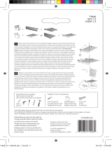
PARTS LIST
John Louis Home Woodcrest Closet System
IMPORTANT: DO NOT RETURN TO STORE!
For missing or damaged parts, technical or assembly questions,
please call John Louis Home Customer Service at 1-800-480-6985
A
Quantity: 1
48 in.
Shelf
B
Quantity: 1
48 in.
Shelf
C
Quantity: 1
48 in.
Shelf
D
Quantity: 2
48 in.
Tower Side
E
Quantity: 1
24 in.
Tower Bottom
F
Quantity: 1
26.25 in.
Tower Top
G
Quantity: 3
24 in.
Adjustable Shelf
H
Quantity: 3
47.5 in.
Metal Bar
I
Quantity: 12
Shelf Mounting
Hardware
J
Quantity: 8
Shelf End
Hardware
K
Quantity: 4
Tower Bracket
Hardware
L
Quantity: 6
J-Hook
Hardware
N
Quantity: 6
Mushroom Cap
P
Quantity: 12 #8 1/2 Trusshead
Screw
T
Quantity: 8 #6 3/4 Screw
Q
Quantity: 4 #8 1 1/4 Screw
U
Quantity: 6 #6 1 1/4 Self
Tapping Screw
M
Quantity: 6
Bar End
Hardware
O
Quantity: 20
Cam Lock Nut
R
Quantity: 4
Barrel Nut
S
Quantity: 17
#4 3/4 Screw
1

BB
Quantity: 46 #8 1 1/2 Screw
CC
Quantity: 46 Wall Anchor
DD
Quantity: 20 Cam Bolt
EE
Quantity: 16 Adjustable Shelf Pin
FF
Quantity: 1 Touch Up Stain Pen
GG
Quantity: 2 Drawer Face
HH
Quantity: 2 Drawer Back
II
Quantity: 2 Left Drawer Side
JJ
Quantity: 2 Right Drawer Side
KK
Quantity: 2 Drawer Back
Y
Quantity: 6 #8 3 Screw
Z
Quantity: 4 Barrel Bolt
AA
Quantity: 4 Full Extension Drawer Slide
V
Quantity: 6 Angle Bracket
W
Quantity: 1 Allen Wrench
X
Quantity: 2 Drawer Handle
LL
Quantity: 4 4mm 1 Drawer Handle Screw
HOW TO CREATE ADJUSTABLE SHELVES
• Position shelf upright.
• Place shelf end bracket onto the
shelf end
• Using lower hole on the shelf end
bracket, drill a pilot hole using a
1/8 in. drill bit.
• Drill the hole 1 to 1 1/4 in. deep.
• Remove shelf end bracket.
• Re-drill at the pilot hole 1 - 1 1/4
in. deep using a 1/4 in. drill bit.
• Insert adjustable shelf pin.
• Repeat steps for the remaining
shelf ends.
2
MM
Quantity: 12 #8 1 screw

IMPORTANT - Read Before Assembly
Assembly instructions are written for 8 ft. configuration A. All
assembly processes are the same for each configuration EXCEPT
for the order or locations of the assembly process. Use selected
configuration for shelf locations.
Shelf lengths and Garment bars may need to be cut depending upon configura-
tion desired.
All cut shelf lengths are used in closet configurations supplied. Depending upon
your closet dimensions, some cut lengths may not be usable.
EXAMPLE: If you choose an 8 ft. closet configuration and the width of your
closet is 8 ft. 4 in., the cut shelf length will be short 4 in. for use. It is recom-
mended that if your closet is over the selected dimension (8 ft.), then choose a
configuration from the next dimension higher (10 ft.).
EXAMPLE: If you choose an 8 ft. closet configuration and the width of your
closet is 7 ft. 6 in., some shelf lengths may need to be cut 6 in. shorter in length
to fit closet dimensions.
24 in. cut shelf lengths used in adjustable shelf tower require holes drilled for
shelf pins. Use supplied instructions located on part list pages for hole size and
locations.
VERIFY SHELF MEASUREMENTS
MEASURE - MARK - MEASURE AGAIN
Chosen configuration may not require use of all hardware or components sup-
plied.
It is recommended to secure hardware into wall studs for overall strength and
stability of closet system.
If choosing a custom designed configuration, modifications to the instructions
provided will be necessary.
STEP 1 - Marking Shelf Locations
1. Using the shelf height measurements from your selected configuration,
measure from the floor up and mark the locations on the wall.
2. Draw a level line equal to the shelf length (Including tower top) on the wall.
3. Repeat for each shelf.
STEP 2 - Shelf Mounting Hardware
Use 3 Shelf Mounting hardware (I) per 48 in. shelf length (A,B,C)
Use 2 Shelf Mounting hardware (I) for tower top location.
Shelf mounting hardware (I) is placed approximately 3 - 6 in. from shelf ends
and centered in between along the back wall. It is recommended to use stud
locations if possible.
1. Using stud finder, locate and mark stud locations at level lines.
2. Center the top screw hole on Shelf Mounting hardware (I) with level line
and mark hole locations.
3. Use supplied wall anchor (CC) at marked location if no stud is present.
4. Secure to wall using #8 1 1/2 in. screw (BB)
5. Repeat for each location.
STEP 3 - Top Shelf Placement
1. Measure and cut shelf if necessary for configuration.
2. Place Shelf End (J) hardware onto 48 in. Shelf (A) end at side wall location.
3. Place shelf onto shelf mounting hardware.
4. Level shelf.
5. Mark a level line on the side wall at the bottom and side of hardware (J).
6. Remove shelf (A), and place hardware (J) at lines and mark screw hole
locations.
7. Use supplied wall anchor (CC) at marked location if no stud is present.
8. Secure to wall using #8 1 1/2 in. screw (BB).
9. Place shelf (A) onto hardware.
3

STEP 4 - Tower Assembly
1. Secure Cam Bolt (DD) into locations at bottom of tower sides (D)
2. Insert Cam Lock (O) into Tower Bottom (E) locations for each side.
3. Secure Tower Sides (D) and Tower Bottom (E) together by turning cam
locks clockwise to tighten.
4. Insert Barrel Nut (R) into locations at top of tower sides (D)
5. Place Tower Top (F) into notched position of tower sides.
6. Insert Barrel Bolt (Z) into location and tighten using supplied wrench (W)
7. On the back of tower sides (The front of the tower is designated by the
nameplate on the tower bottom shelf), center tower bracket (K) in space
between 1st & 2nd groove at top location and 2nd groove & bottom for
bottom location for each tower side (2 per side).
8. Secure tower bracket (K) using #6 3/4 in. screw (T).
STEP 5 - Tower Placement
Determine if you prefer the shelf that meets the tower top shelf to have an “Shelf
End” or a “Continual Seam” Style
.
For “Continual Seam” style skip Step 6 - Mounting Shelf End To Tower. You will
use an angle bracket to level shelf with tower top shelf.
1. Place Shelf End hardware (J) on end of top shelf (A).
2. Place assembled tower onto shelf mounting clips.
3. Slide tower over so that shelf and tower top are against each other.
4. Level / plum tower and mark bracket hole locations on wall.
5. Use supplied wall anchor (CC) at marked location if no stud is present.
6. Secure to wall using #8 1 1/2 in. screw (BB).
4

STEP 6 - Attach Shelf End To Tower
1. Place Shelf End hardware (J) onto shelf end if required.
2. Level shelf.
3. Mark a level line on the tower side at the bottom and side of bracket (J).
4. Remove shelf and place hardware (J) at lines and secure to tower side
using #8 1 in. screw (BB) at top hole location.
5. Place shelf onto hardware.
STEP 7 - Placing Additional Shelves
1. Measure and cut shelf if necessary for configuration.
2. Use Stain pen (FF) to touch up cut shelf end.
3. Proceed to Step 3 for mounting Shelf End Hardware (J) to sidewall.
4. Proceed to Step 6 for mounting Shelf End Hardware (J) to tower side.
5. Secure all shelves into place using #4 1/4 in. screw (S) at underside loca-
tions of Shelf Mounting Hardware (I) and Shelf End Hardware (J).
STEP 8 - J-Hooks & Angle Brackets
Angle brackets can be used without J-Hooks as underside support. This allows
for the shelf to be “Free Hanging” (Used without securing to a sidewall).
(Bracket With Bar) (Bracket For Underside Support)
5

To use without Garment Bar & J-Hook, skip step 1 and proceed with process.
1. Attach J-Hook (L) to Angle Bracket (V) using #8 1 in. screw (MM) at pilot
hole location on angle bracket.
2. Place angle bracket snuggly behind front shelf rail under shelf at desired
location. Typically, 4-6 slats in from end of shelf.
3. Insert #8 3 in. screw (Y) and tap to mark location on wall.
4. Remove angle bracket and use supplied wall anchor (CC) at marked loca-
tion if no stud is present.
5. Position the angle bracket at 90 degree angle and extend tip screw through
angle bracket to insert into location on wall.
6. Rotate angle bracket into position and secure screw.
7. Insert Mushroom Cap (N) into angle bracket screw hole.
8. Repeat for remaining angle brackets.
STEP 9 - Garment Bars & Bar Ends
1. Based upon your configuration, measure space for garment bar (H).
2. Cut bar according to desired length
3. Insert Garment Bar End (M)
4. Tighten Bar End (M) by turning clockwise until secure.
5. Place bar with bar ends attached onto j-hooks
6. Secure bar to j-hook with #6 1 1/4 in self tapping screw (U).
7. Repeat for remaining bars.
STEP 10 - Tower Drawer
1. Insert cam bolts (DD) into left drawer side (II) and at hole locations.
2. Repeat for right drawer side (JJ).
3. Align interior grooves on drawer sides (II, JJ) and drawer back (HH) then
insert side cam bolts into drawer back (HH) at hole locations.
4. Insert cam locks (O) into drawer back (HH) at hole locations and turn clock-
wise to tighten drawer sides to drawer back (Do not overtighten).
5. Insert drawer bottom (KK) into interior grooves.
6. Insert cam bolts (DD) into back of drawer face (GG) at hole locations.
7. Insert drawer handle screws (LL) into drawer face at hole locations.
8. Attach drawer handle (X) to drawer face.
9. Insert cam locks (O) into left and right drawer side at hole locations
10. Align drawer bottom into interior groove on drawer face and cam bolts into
drawer side locations.
11. Secure drawer face to sides by turning cam locks clockwise tighten (Do not
overtighten).
12. Repeat for remaining drawers.
6

STEP 11 - Drawer Slide Positioning
Slide position on drawers are dependent upon drawer location
inside tower.
Based upon your chosen configuration, see below for slide posi-
tion.
Drawers located at top of tower (from top to bottom)
• Drawer 1: slide position A / tower groove 1 (suppiled)
• Drawer 2: slide position B / tower groove 3 (suppiled)
• Drawer 3: slide position A (optional) / tower groove 4
Drawers located at bottom of tower (from bottom to top)
• Drawer 1: slide position A / tower groove 1 (suppiled)
• Drawer 2: slide position B / tower groove 2 (suppiled)
• Drawer 3: slide position A (optional) / tower groove 4
1. Remove interior of Drawer Slide (AA) by fully extending slide until lever is
exposed.
2. Slide lever to release interior
3. Determine slide drawer side position from above listing.
4. Place slide interior onto drawer side with closed end facing drawer face.
5. Center align the interior drawer slide onto the required score mark.
6. Secure the front interior slide to drawer side using the #8 1/2 screw (P) in
the vertical oval hole location.
7. Secure the back interior slide to drawer side using #8 1/2 screw (P) in the
horizontal oval hole location.
8. Determine slide tower groove position from above listing.
9. Place the exterior drawer slide into required tower groove position with
rubber stopper facing back wall.
10. Secure exterior drawer slide to tower side using #8 1 1/4 screw (Q).
11. Repeat for remaining slides.
12. Insert drawer into tower and connect slides together.
13. Repeat for remaining drawers.
14. Loosen #8 1/2 screw (P) on front slide position on the drawer side for
drawer spacing adjustment and tighten when adjusted.
7

STEP 12- Adjustable Shelves
Based upon your chosen configuration, if your drawers are not
positioned at tower top, one (1) adjustable shelf must be positioned
as a Drawer Top.
To create additional adjustable shelves from excess shelf cuts,
please refer to the process “HOW TO CREATE ADJUSTABLE
SHELVES” in the parts list section of the instructions.
If shelf is too tight in tower, place shelf upright and tap pins with
hammer to shorten the length of the adjustable shelf pin.
1. Insert Adjustable Shelf Pins (EE) into locations at adjustable shelf (G) ends.
2. Repeat for all remaining adjustable shelves.
3. Align interior tower grooves with adjustable shelf pins and insert into tower.
4. Repeat for remaining adjustable shelves.
Contact
For questions concerning missing or damaged parts, technical specs and / or
assembly help, please contact John Louis Home Customer Service at:
1.800.480.6985
www.johnlouishome.com
John Louis Home
4301 Rider Trail North
Suite 150
Earth City, Missouri 63045
United States
© 2011 John Louis Inc., All Rights Reserved.
8

CONFIGURATION NOTES:
• Install tower prior to shelves.
• Requires cutting of A,B,C shelf.
• Additional shelves created from
C shelf.
• Utilizes bottom drawer placement.
• Design can be reversed.
10‘ (3.05 m)
10‘
(3.05 m)
6‘ (1.82m)8‘ (2.43m)
84”
(213.3 cm)
42”
(106.6cm)
42”
(106.6cm)
26.25”
(66.675cm)
45.75”
(116.20 cm)
6’ CLOSET CONFIGURATION A • A CONFIGURACION DE 1.82M • A CONFIGURATION DE 1.82M
6”
(15.2 cm)
45”
(114.3 cm)
72”
(183 cm)
A
B
H
H
G
G
G
C
25

CONFIGURATION NOTES:
• Requires cutting or notchng out
tower area of baseboard for
floor placement.
• Install tower prior to shelves.
• Requires cutting of A,B,C shelf.
• Additional shelves created from
C shelf.
• Utilizes top drawer placement.
• Design can be reversed.
10‘ (3.05 m)
10‘
(3.05 m)
6‘ (1.82m)8‘ (2.43m)
84”
(213.3 cm)
42”
(106.6cm)
42”
(106.6cm)
26.25”
(66.675 cm)
25.75”
(65.4 cm)
45.75”
(116.20 cm)
6’ CLOSET CONFIGURATION B • B CONFIGURACION DE 1.82M • B CONFIGURATION DE 1.82M
45.75”
(116.20 cm)
72”
(183 cm)
A
B
H
H
G
G
G
H
C
6”
(15.2 cm)
45”
(114.3 cm)
26

CONFIGURATION NOTES:
• Requires cutting of C shelf.
• Additional shelves created from
C shelf.
• Utilizes bottom drawer placement.
• Design can be reversed.
10‘ (3.05 m)
10‘
(3.05 m)
6‘ (1.82m)8‘ (2.43m)
84”
(213.3 cm)
72”
(183 cm)
42”
(106.6cm)
42”
(106.6cm)
26.25”
(66.675cm)
21.75”
(55.24 cm)
48”
(121.92 cm)
8’ CLOSET CONFIGURATION A • A CONFIGURACION DE 2.43M • A CONFIGURATION DE 2.43M
21.25”
(53.96 cm)
96”
(243.84 cm)
G
G
G
C
A
H
B
H
C
H
6”
(15.2 cm)
27

CONFIGURATION NOTES:
• Requires cutting of C shelf.
• Additional shelves created from
C shelf.
• Utilizes bottom drawer placement.
• Design can be reversed.
10‘ (3.05 m)
10‘
(3.05 m)
6‘ (1.82m)8‘ (2.43m)
84”
(213.3 cm)
42”
(106.6cm)
42”
(106.6cm)
26.25”
(66.675cm)
21.75”
(55.24 cm)
48”
(121.92 cm)
8’ CLOSET CONFIGURATION B • B CONFIGURACION DE 2.43M • B CONFIGURATION DE 2.43M
21.25”
(53.96 cm)
96”
(243.84 cm)
G
G
G
A
H
B
H
C
C
H
6”
(15.2 cm)
28

CONFIGURATION NOTES:
• Install shelves first then proceed
to tower installation.
• Requires cutting or notchng out
tower area of baseboard for
floor placement.
• Utilizes top drawer placement.
• Design can be reversed.
10‘ (3.05 m)
10‘
(3.05 m)
6‘ (1.82m)8‘ (2.43m)
84”
(213.3 cm)
42”
(106.6cm)
42”
(106.6cm)
48”
(121.92 cm)
8’ CLOSET CONFIGURATION C • C CONFIGURACION DE 2.43M • C CONFIGURATION DE 2.43M
96”
(243.84 cm)
G
G
G
B
H
48”
(121.92 cm)
A
H
48”
(121.92 cm)
C
H
6”
(15.2 cm)
29

CONFIGURATION NOTES:
• Requires cutting of C shelf.
• Utilizes bottom drawer placement.
• Design can be reversed.
10‘ (3.05 m)
10‘
(3.05 m)
6‘ (1.82m)8‘ (2.43m)
84”
(213.3 cm)
42”
(106.6cm)
42”
(106.6cm)
26.25”
(66.675cm)
48”
(121.92 cm)
45.75”
(116.20 cm)
10’ CLOSET CONFIGURATION A • A CONFIGURACION DE 3.05M • A CONFIGURATION DE 3.05M
120”
(304.8 cm)
G
G
G
A
H
B
H
C
H
72”
(183 cm)
6”
(15.2 cm)
45”
(114.3 cm)
30

CONFIGURATION NOTES:
• Install tower prior to shelves.
• Requires cutting of C shelf.
• Utilizes bottom drawer placement.
• Design can be reversed.
10‘ (3.05 m)
10‘
(3.05 m)
6‘ (1.82m)8‘ (2.43m)
84”
(213.3 cm)
42”
(106.6cm)
42”
(106.6cm)
26.25”
(66.675cm)
48”
(121.92 cm)
45.75”
(116.20 cm)
10’ CLOSET CONFIGURATION B • B CONFIGURACION DE 3.05M • B CONFIGURATION DE 3.05M
45”
(114.3 cm)
120”
(304.8 cm)
G
G
G
A
H
B
H
C
H
6”
(15.2 cm)
31
/