Page is loading ...

12 IN. DEEP PREMIER CLOSET ORGANIZER ASSEMBLY INSTRUCTIONS
16 IN. DEEP DELUXE CLOSET ORGANIZER ASSEMBLY INSTRUCTIONS
Sistema De Armario - Instrucciones de esamblaje Systeme De Placard - Directives d assemblage
For Use With Model JLH-525, JLH-526, JLH-528 & JLH-529
SKU# 707

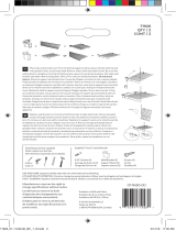
PARTS LIST Lista De Piezas Liste Des Piéces
IMPORTANT: DO NOT RETURN TO STORE!
For missing or damaged parts, technical or assembly questions,
please call John Louis Customer Service at 1-800-480-6985
IMPORTANTE: ¡NO LO DEVUELVA A LA TIENDA!
Llame al servicio al cliente local de John Louis al 1-800-480-6985
para aclarar sus dudas sobre pérdidas, daños, asuntos écnicos y ensamblaje.
IMPORTANT: NE PAS RENVOYER OU RAPPORTER AU MAGASIN!
Si vous avez une question concernant l’assemblage, des piéces manquantes ou endommagées ou
un probléme technique, appelez le Service á la clientéle de John Louis au 1-800-480-6985.
A
Quantity: 2 72 in. Shelf / Estantes de 1,8 m / Tablette de 183 cm
C
Quantity: 2 24 in. Shelf / Estantes de 61 cm / Tablette de 61 cm
E
Quantity: 2 72 in. Tower Side / Torre Lateral de 1,8 m / Côté Tour de
183 cm
B
Quantity: 1 48 in. Shelf / Estantes de 1,2 m / Tablette de 121 cm
D
Quantity: 1 24 in. Cam Shelf / Cam Estantes de 61 m / Cam Tablette
de 121 cm
F
Quantity: 6 Angle Bracket / Ménsula en escuadra / Équerre de support
G
Quantity: 2 72 in. Wardrobe Bar / Barra del armario de 1,8 m / Barre
de penderie de 183 cm
H
Quantity: 1 48 in. Wardrobe Bar / Barra del armario de 1,2 m / Barre de
penderie de 121 cm
1

U
Quantity: 6 #6 1 1/4 Self
Tapping Screw
O
Quantity: 4
Cam Lock Nut
Tuerca de leva
Écrou de came
DD
Quantity: 4
Cam Bolt
Perno de leva
Boulon de came
EE
Quantity: 16
Adjustable Shelf Pin
Pasador para estantería
Support de tablette
FF
Quantity: 1
Touch Up Stain Pen
Tinte de color pluma
Colorant de plume
2
I
Quantity: 6
J-Hook
Gancho en J
Crochet en J
L
Quantity: 14
Shelf mounting L- Clip
Estante clip de montaje
Clip tablette
N
Quantity: 6
Bar End
Tapa del tope de la barra
Capuchon d’extrémité
de barre
M
Quantity: 4
Vertical Clip
Grapa vertical
Attache verticale
P
Quantity: 4
Mushroom Cap
Tapa en forma de
hongo
Chapeau de vis
N
Quantity: 14
#6 3/4 in. / 1,9 cm
O
Quantity: 24
#4 3/4 in. / 1,9 cm
Quantity: 64 #8 1 1/2 in. / 3,81 cm
P
Quantity: 56 Wall Anchor / Anclaje de pared /
Boulon d’ancrage
QO
Quantity: 6 #8 3 in. / 7,62 cm
K
Quantity: 6
Shelf End
Tope del estante
Extrémité de tablette
J
Quantity: 6
Tower Bracket
Ménsula torre
Équerre de tour
Quantity: 12
#8 1 in. / 2,54 cm
N
Contact Contact0 Contacter
For questions concerning missing or damaged parts, technical specs and / or assembly help, please contact John Louis Home Customer Service at:
Si tiene preguntas sobre partes faltantes o dañadas, especicaciones técnicas o asistencia para el armado, comuníquese con el Servicio al Cliente de John Louis
Home:
Pour toute question relative à des pièces manquantes ou endommagées, toute spécication technique et/ou aide au montage, contactez le service après-vente de
John Louis Home au :
1.800.480.6985 [email protected] www.johnlouishome.com
John Louis Home 4301 Rider Trail North Suite 150 Earth City, Missouri 63045 USA
© 2012 John Louis Inc., All Rights Reserved.

3
IMPORTANT - Read Before Assembly
12 in. deep Premier Organizer and 16 in. deep Deluxe Organizer
use the same assembly instruction process EXCEPT DURING
THE J-HOOK PLACEMENT ON THE ANGLE BRACKET.
Assembly instructions are written for 8 ft. conguration A.
All assembly processes are the same for each conguration
EXCEPT for the order or locations of the assembly process.
Use selected conguration for shelf locations.
Shelf lengths and Garment bars may need to be cut depending upon conguration
desired.
All cut shelf lengths are used in closet congurations supplied. Depending upon
your closet dimensions, some cut lengths may not be usable.
EXAMPLE: If you choose an 8 ft. closet conguration and the width of your
closet is 8 ft. 4 in., the cut shelf length will be short 4 in. for use. It is recommended
that if your closet is over the selected dimension (8 ft.), then choose a congura-
tion from the next dimension higher (10 ft.).
EXAMPLE: If you choose an 8 ft. closet conguration and the width of your
closet is 7 ft. 6 in., some shelf lengths may need to be cut 6 in. shorter in length
to t closet dimensions.
VERIFY SHELF MEASUREMENTS
MEASURE - MARK - MEASURE AGAIN
Chosen conguration may not require use of all hardware or components sup-
plied.
It is recommended to secure hardware into wall studs for overall strength and
stability of closet system.
If choosing a custom designed conguration, modications to the instructions pro-
vided will be necessary.
All congurations provided may be reversed.
STEP 1 - Determining Your Dimensions
1. Locate your desired conguration (Instructions are written for 8 ft.
conguration A).
2. Top hang shelf is created with 1 - 6 ft. shelf length.
3. Double hang is created by cutting a 4 ft. shelf to 45.5 in. wide.
4. Long hang is created by cutting a 6 ft. shelf to 24 in. wide. (If your closet
is greater or less than 8 ft. wide you will cut your shelf greater or
less that distance. EXAMPLE: Closet is 8 ft. 5 in. - cut shelf 2 ft. 5 in.
EXAMPLE: Closet is 7 ft. 10 in. - cut shelf 1 ft. 8 in.)
STEP 2 - Marking Measurements On Wall
1. Locate the 3 main shelf height locations for your conguration.
2. Measure up from the oor & mark the 84 in. location.
3. Measure down 42 in. from the 84 in. mark & mark the 42 in. location.
4. Measure down 12 in. from the 84 in. mark & mark the 72 in. location.
84 in. - top shelf
42 in. - double hang shelf
72 in. - long hang shelf
5. Draw a 6 ft. long level line out from wall end at 84 in. location.
6. Draw a 4 ft. long level line out from wall end at 42 in. location.
7. Draw a 2 ft. long level line out from wall end at 72 in. location.
8. Locate stud locations at level lines.

4
STEP 3 - Installing Top Shelf
It is recommended to install hardware into wall studs. Typically 16 in. on
center. Use 50 lb. wall anchors provided if no stud is present.
Space shelf mounting L-clip hardware equidistant in the following manner:
• 4-5 L-clip hardware per 6 ft. shelf span
• 3-4 L-clip hardware per 4 ft. shelf span
• 2 L-clip hardware per 2 ft. shelf span
1. Center the top screw hole of the shelf mounting L-clip hardware with the
level line & mark all hole locations.
2. Secure L-clip to wall using #8 1 1/2 in. screws at hole locations (Use wall
anchors provided if no stud is present).
3. Repeat for all L-clips at top shelf height location.
4. Place Shelf End hardware onto 6 ft. shelf end at side wall location.
5. Place shelf onto shelf mounting hardware.
6. Level shelf.
7. Mark a level line on the side wall at the bottom and side of hardware.
8. Remove shelf & place shelf end hardware at lines and mark screw hole
locations.
9. Secure shelf end hardware to wall using #8 1 1/2 in. screws. Use supplied
wall anchor at marked location if no stud is present.
10. Place shelf into shelf end hardware & onto L-clip hardware.
11. Secure shelf to hardware using #4 3/4 in. screws at all hardware locations.
STEP 4 - Installing Shelf Tower
1. Mark a line on the wall at the center of the last slat on the top shelf.
2. Measure down 72 in. & mark location.
3. Mark a plumb line on the wall down to the 72 in. mark.
4. Measure down & mark the 3 in., 35 in. & 67.5 in locations on the line.

5
5. Measure across 25.25 in. (Critical Dimension) from plumb line & mark
location.
6. Mark a plumb line on the wall down 72 in. from shelf.
7. Level across & mark the 3 in., 35 in. & 67.5 in. locations on line.
8. At the 3 in., 35 in. & 67.5 in. marks, center the middle hole of the tower
bracket & mark bracket hole locations (bracket anges are positioned
towards tower inside).
9. Secure tower bracket to wall using #8 1 1/2 in. screws.
10. Repeat at all bracket locations.
11. Position tower sides with grooves facing up.
12. Locate cam bolt positions at bottom of tower sides.
13. Secure cam bolt into pre-pilot hole at location.
14. Repeat for 2nd location & 2nd tower side.
15. Select tower bottom shelf (typically the logo shelf).
16. Insert cam nut with arrow facing toward bolt hole.
17. Repeat for each location.

6
18. Insert cam bolts into bottom shelf at hole locations.
19. Secure bottom shelf to side by tightening cam nut in a clockwise direction.
20. Repeat for 2nd cam nut & 2nd tower side.
21. Position tower into tower brackets (logo typically used as front of tower).
22. Maneuver tower top into underside of top shelf.
23. Ensure that shelf underside is snug within tower sides.
24. Secure tower sides to brackets using #6 3/4 in. screws at all locations.
25. Place 2 vertical clips per side onto top shelf slat.
• Clips should align over shelf slat & ush with tower side.
• Clips may ush inside or outside of tower side & both sides of verti-
cal clips may be used.
26. Secure the vertical clip to the top shelf slat using #4 3/4 in. screw.
27. Secure the vertical clip to the tower side using #6 3/4 in. screw.
28. Repeat for all vertical clips.
• For an alternative option, you may screw directly through the shelf
slat & into the tower side using #6 3/4 in. screws (if choosing this
option, it is recommended to pre-pilot the location prior to securing
with screw).
STEP 5 - Installing Secondary Shelves
1. Double hang shelf is created by cutting a 4 ft. shelf to 45.5 in..
2. Long hang is created by cutting a 6 ft. shelf to 24 in. wide. (If your closet
is greater or less than 8 ft. wide you will cut your shelf greater or
less that distance. EXAMPLE: Closet is 8 ft. 5 in. - cut shelf 2 ft. 5 in.
EXAMPLE: Closet is 7 ft. 10 in. - cut shelf 1 ft. 8 in.)
3. Mark L clip hardware locations for secondary shelves.
• It is recommended to install hardware into wall studs. Typically 16 in.
on center. Use 50 lb. wall anchors provided if no stud is present.
• Space L-clip hardware equidistant in the following manner:
4-5 L-clip hardware per 6 ft. shelf span
3-4 L-clip hardware per 4 ft. shelf span
2 L-clip hardware per 2 ft. shelf span

7
4. Center the top screw hole of the shelf mounting L-clip hardware with the
level line & mark all hole locations.
5. Secure L-clip to wall using #8 1 1/2 in. screws at hole locations (Use wall
anchors provided if no stud is present).
6. Repeat for all L-clips at shelf height location.
7. Double check required shelf measurement at shelf height location.
8. Measure, mark & cut required shelf dimensions.
9. Place shelf end hardware onto shelf end at side wall location.
10. Place shelf onto shelf mounting hardware.
11. Level shelf.
12. Mark a level line on the side wall at the bottom and side of hardware.
13. Place shelf end hardware onto shelf end at tower location.
14. Level shelf.
15. Mark a level line on the tower side at the bottom and side of hardware.
16. Remove shelf & place shelf end hardware at lines and mark screw hole
locations.
17. Secure shelf end hardware to wall using #8 1 1/2 in. screws. Use supplied
wall anchor at marked location if no stud is present.
18. Secure shelf end hardware to tower side using #6 3/4 in. screws.
19. Place shelf into shelf end hardware & onto L-clip hardware.
20. Secure shelf to hardware using #4 3/4 in. screws at all hardware locations.

8
21. Repeat steps for additional secondary shelf.
STEP 6 - Installing Angle Brackets
16 in. Angle Bracket used with 16 in. deep Deluxe Organizer
1. Measure 3 in. back from front of angle bracket & mark location.
2. Place J-hook snug with underside of bracket & align the front edge of the
J-hook with the mark.
3. Secure using #8 1 in. screws.
4. Repeat for each angle bracket & J-hook.
12 in. Angle Bracket used with 12 in. deep Premier Organizer
On the 12 in. angle bracket install it is recommended to pre-pilot screw
hole locations with a 1/8 in. drill bit prior to securing the J-hook to the
angle bracket.
1. Place J-hook snug with underside of bracket & ush the front edge of the
J-hook with the front of the angle bracket.
2. Secure using #8 1 in. screws.
3. Repeat for each angle bracket & J-hook.
4. Insert #8 3 in. screw into angle bracket.
5. Position angle bracket 6 in. or 4 slats in from shelf end (bracket may be
positioned in your desired location).
6. Ensure bracket is square with shelf underside & back wall.
7. If no stud is present, mark hole location by driving screw into drywall.
8. Install anchor if necessary.
9. Secure angle bracket using #8 3 in. screw.
10. Repeat for 2nd angle bracket.
11. Repeat for all shelf locations.

9
STEP 7 - Installing Garment Bars
1. Locate the bar dimensions in you conguration guide
2. The double hang garment bars are created by cutting 2 bars to 45 in. wide.
3. The long hang garment bar is created by cutting a bar to 23.5 in. wide.
4. Double check bar measurements.
5. Measure required dimension, mark & cut bar.
6. Repeat for all bars.
7. Insert bar end into end of garment bar.
8. Turn clockwise to tighten & repeat for each bar end.
9. Place garment bar onto J-hooks.
10. Secure garment bar to J-Hooks using #6 1 1/4 in. self tapping screws.
11. Repeat for all garment bar locations.
STEP 8 - Installing Adjustable Shelves
1. Select a 24 in. adjustable shelf
2. Insert shelf pin into shelf at hole location.
3. Repeat at each hole location.

10
Creating Adjustable Shelves
Put your excess cuts back into your closet. Any material greater than 24 in.
wide can be used as an additional shelf.
Cut excess lengths to 24 in. wide to use as tower shelves & place where
ever you choose.
In an 8 ft. closet conguration your 4 ft. of excess shelving can create 2
additional adjustable shelves.
4. Place the shelf into the tower by inserting the pins into the tower grooves.
5. Create a shoe shelf by inserting the shelf upside down with the back one
groove higher than the front.
1. Measure required dimension, mark & cut shelf.
2. Place shelf end bracket onto shelf.
3. Using the lower hole location on the bracket, drill a pilot hole using a 1/8 in.
drill bit.
4. Remove the shelf end bracket.
5. Re-drill hole 1 - 1 1/4 in. deep using a 1/4 in. drill bit.
6. Repeat steps for each shelf end.
7. Insert shelf pin into holes at each end.
STEP 9 - Final Touches
1. Insert mushroom caps into all angle brackets.
2. Touch up scratches & cut ends with stain pen provided.
/