Page is loading ...

1
NOVEMBER 2019CP5077361
6' 8' 10'
INSTALLATION GUIDE – GUÍA DE INSTALACIÓN

2
Size: 8.5”X11”
Get fast support at 1-866-264-1964 or
Support@closetsbyliberty.com
Thank you for your recent purchase.
If you’ve had a positive buying experience, we would be grateful if you would leave
us a positive product review.
If you are not entirely delighted with your overall experience, please call us at
1-866-264-1964 so we can discuss any issues you may have.
Review your installation instructions for troubleshooting tips. Find the latest version online
at https://www.libertyhardware.com.
Contact our customer care team by phone at 1-866-264-1964 Monday through Friday from
9:00AM until 5:00PM EST.
E-mail our customer care team at
Support@closetsbyliberty.com
If you need installation assistance, a new part, or have any questions please use the following product
support options:
STOP STOP
DO NOT RETURN TO THE STORE.
We are here to help!
Size: 8.5”X11”
Obtenga soporte rápido llamando al 1-866-264-1964
o en Support@closetsbyliberty.com
Si su experiencia de compra ha sido positiva, le agradeceremos que nos deje una
reseña de producto positiva.
Si su experiencia general no ha sido completamente satisfactoria, le rogamos nos
llame al 1-866-264-1964 para que hablemos sobre cualquier problema que pueda
tener.
ALTO ALTO
No devuelva el producto a la tienda.
¡Estamos para ayudar!
Revise las instrucciones de instalación donde encontrará consejos para solucionar prob-
lemas. Encuentre la última versión en internet en https://www.libertyhardware.com.
Póngase en contacto con nuestro equipo de atención al cliente llamando al
1-866-264-1964 de lunes a viernes de 9:00 a.m. hasta las 5:00 p.m. EST.
Envíe un correo electrónico a nuestro equipo de atención al cliente en
Support@closetsbyliberty.com
Si necesita ayuda para la instalación, un repuesto nuevo o tiene alguna pregunta, use las siguientes
opciones de soporte de producto:
Front Back
Gracias por su compra reciente.

3
Size: 8.5”X11”
Get fast support at 1-866-264-1964 or
Support@closetsbyliberty.com
Thank you for your recent purchase.
If you’ve had a positive buying experience, we would be grateful if you would leave
us a positive product review.
If you are not entirely delighted with your overall experience, please call us at
1-866-264-1964 so we can discuss any issues you may have.
Review your installation instructions for troubleshooting tips. Find the latest version online
at https://www.libertyhardware.com.
Contact our customer care team by phone at 1-866-264-1964 Monday through Friday from
9:00AM until 5:00PM EST.
E-mail our customer care team at
Support@closetsbyliberty.com
If you need installation assistance, a new part, or have any questions please use the following product
support options:
STOP STOP
DO NOT RETURN TO THE STORE.
We are here to help!
Size: 8.5”X11”
Obtenga soporte rápido llamando al 1-866-264-1964
o en Support@closetsbyliberty.com
Si su experiencia de compra ha sido positiva, le agradeceremos que nos deje una
reseña de producto positiva.
Si su experiencia general no ha sido completamente satisfactoria, le rogamos nos
llame al 1-866-264-1964 para que hablemos sobre cualquier problema que pueda
tener.
ALTO ALTO
No devuelva el producto a la tienda.
¡Estamos para ayudar!
Revise las instrucciones de instalación donde encontrará consejos para solucionar prob-
lemas. Encuentre la última versión en internet en https://www.libertyhardware.com.
Póngase en contacto con nuestro equipo de atención al cliente llamando al
1-866-264-1964 de lunes a viernes de 9:00 a.m. hasta las 5:00 p.m. EST.
Envíe un correo electrónico a nuestro equipo de atención al cliente en
Support@closetsbyliberty.com
Si necesita ayuda para la instalación, un repuesto nuevo o tiene alguna pregunta, use las siguientes
opciones de soporte de producto:
Front Back
Gracias por su compra reciente.

4
W
D
H
Outside Width (W)
3 Towers
68-7/8"
Height (H) = 83-1/2"
Depth (D) = 16-3/4"
Allow for 32" for depth measurement when selecting drawer locations so that the drawer can be fully opened.
Deje 32" (81.28 cm) para medir la profundidad al seleccionar la ubicación de los cajones de manera que puedan
abrirse completamente.
Ancho exterior (W)
3 torres
68-7/8"
Altura (H) = 83-1/2" (2.12 m)
Profundidad (D) = 16-3/4" (42.5 cm)
MEASURE YOUR SPACE - 6 ft
–
MIDA SU ESPACIO: 6 ft (1.8 m)

5
W
D
H
Outside Width (W)
4 Towers 2 Towers + 48" Shelf
91-5/16" 94-7/16"
Height (H) = 83-1/2"
Depth (D) = 16-3/4"
Allow for 32" for depth measurement when selecting drawer locations so that the drawer can be fully opened.
Deje 32” (81.28 cm) para medir la profundidad al seleccionar la ubicación de los cajones de manera que puedan
abrirse completamente.
Ancho exterior (W)
4 torres 4 torres 2 torres + estante de 48" (1.2 m)
91-5/16" 94-7/16"
Altura (H) = 83-1/2" (2.12 m)
Profundidad (D) = 16-3/4" (42.5 cm)
MEASURE YOUR SPACE - 8 ft
–
MIDA SU ESPACIO: 8 ft (2.4 m)

6
W
D
H
Outside Width (W)
5 Towers
113-3/4"
Height (H) = 83-1/2"
Depth (D) = 16-3/4"
Allow for 32" for depth measurement when selecting drawer locations so that the drawer can be fully opened.
Deje 32" (81.28 cm) para medir la profundidad al seleccionar la ubicación de los cajones de manera que puedan
abrirse completamente.
MEASURE YOUR SPACE - 10 ft
–
MIDA SU ESPACIO: 10 ft (3.05 m)
Ancho exterior (W)
5 torres
113-3/4"
Altura (H) = 83-1/2" (2.12 m)
Profundidad (D) = 16-3/4" (42.5 cm)

7
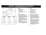
AA
Top Frame
Screw
Tornillo de
armazón
superior
BB
Leveling
Foot
Pata de
nivelado
CC
Stabilizer Bar Screw
Tornillo de barra
estabilizadora
EE
Drywall Anchors
Anclajes para tablero
de pared
FF
Anti-Tip Bracket Screw
Tornillo de soporte
antivuelco
RR
Front Frame
Screw
Tornillo de
armazón
frontal
REQUIRED TOOLS
–
HERRAMIENTAS REQUERIDAS
TOWER HARDWARE –
ADITAMENTOS PARA LA TORRE

8
*Note: Long vertical sides (B) are symmetrical top-to-bottom, do not have an incorrect orientation, and can be
installed in either front or back. Horizontal headers (A, C) are symmetrical front-to-back and can be
installed on left or right sides.
A*
Frame Header
(Top of Frame)
H
Front Stabilizer Cover
Cubierta del estabilizador
frontal
I
Rear Stabilizer Cover
Cubierta del estabilizador
trasero
J
Top Rear Stabilizer Bar
Barra estabilizadora de
la parte superior trasera
K
Stabilizer Bar
Barra estabilizadora
L
Shelf Brackets
Soportes de estante
E
Top Shelf
Estante superior
F
Slide On Shelf
Estante deslizante
B*
Long
Vertical
Sides
lados
verticales
largos
C*
Frame Footer
(Bottom of Frame)
Pie del armazón
(Parte inferior del armazón)
Cabecera del armazón
(Parte superior del armazón)
*Nota: Los lados verticales largos (B) son simétricos de arriba a abajo, no tienen una orientación incorrecta y se
pueden instalar al frente o atrás. Las cabeceras horizontales (A, C) son simétricas del frente a atrás y se pueden
instalar en los lados izquierdo o derecho.
*Note: Long vertical sides (B) are symmetrical top-to-bottom, do not have an incorrect orientation, and can be
installed in either front or back. Horizontal headers (A, C) are symmetrical front-to-back and can be installed on
left or right sides.
TOWER PARTS IDENTIFICATION
–
IDENTIFICACIÓN DE LAS PARTES DE LA TORRE

9
Long vertical sides (B) come pre-assembled with couplers in place.
Assemble two long vertical sides (B) with the horizontal top (A) and bottom (C) headers.
Secure the top with screws (AA) and the bottom with levelers (BB).
Repeat for an additional frame. (The first four steps of assembly are completed with the frame laying on its side.)
Los lados verticales largos (B) ya vienen ensamblados con los acopladores en su lugar.
Ensamble dos lados verticales largos (B) con las cabeceras horizontales superior (A) e inferior (C).
Fije la parte superior con tornillos (AA) y la inferior con niveladores (BB).
Repita para un armazón adicional (los primeros cuatro pasos del ensamblaje se completan con el armazón apoyado en su lado).
Before beginning, identify components and read all instructions.
Antes de comenzar, identifique los componentes y lea todas las instrucciones.
2
1
2
1
4
1
BB
AA
B
B
A
C
3
Note: Long vertical sides (B) are symmetrical top-to-bottom, do not have an incorrect orientation, and can be
installed in either front or back. Horizontal headers (A, C) are symmetrical front-to-back.
Nota: Los lados verticales largos (B) son simétricos de arriba a abajo, no tienen una orientación incorrecta y
se pueden instalar al frente o atrás. Las cabeceras horizontales (A, C) son simétricas del frente a atrás.
Top of assembly
Header (A) has 4 holes for
mounting hanging bars
Parte superior del conjunto
La cabecera (A) tiene 4
agujeros para montar las
barras de colgar
TOWER ASSEMBLY (ALL CONFIGURATIONS)
ENSAMBLAJE DE LA TORRE (TODAS LAS CONFIGURACIONES)

10
1
1
3
3
2
2
J
K
CC
Top rear of assembly
Install a top stabilizer bar (K) and rear stabilizer bar (J) to one side of the frame. Secure with screws (CC).
Note: Rear stabilizer bar bracket (J) screw opening must face top of unit.
Instale una barra estabilizadora superior (K) y una barra estabilizadora trasera (J) a un lado del armazón. Asegúrela
con los tornillos (CC).
Nota: La apertura del tornillo para el soporte de la barra estabilizadora trasera (J) debe mirar hacia la parte
superior de la unidad.
Install the remaining stabilizer bar (K) to bottom inside of the frame. Secure with screws (CC).
Instale la barra estabilizadora que queda (K) en la parte inferior dentro del armazón. Asegúrela con los tornillos (CC).
1
2
3
K
CC
Bottom front of
assembly
Parte superior trasera
del conjunto
Parte frontal inferior
del conjunto
Stabilizer Bars: Install with slots facing upwards
and the closed side of the bar facing inwards.
WARNING - ADVERTENCIA
Barras estabilizadoras: Instálelas con las ranuras
mirando hacia arriba y el lado cerrado de la barra
mirando hacia adentro.

11
1
2
4
1
1
CC
Install second half of the frame to the footer and header stabilizer bars. Secure with screws (CC).
Instale la segunda mitad del armazón en las barras estabilizadoras del pie y la cabecera. Asegúrela con los
tornillos (CC).
Stand frame upright with the opening facing
toward you. Place assembled tower into position
at final location.
Coloque el armazón de pie con la apertura
mirando hacia usted. Coloque la torre ensamblada
en posición en la ubicación final.
Fasten 2 of the remaining small head screws (RR)
at each location marked (A).
Apriete 2 de los tornillos de cabeza pequeña que
quedan (RR) en cada ubicación marcada (A).
6
5
RR
A
A
WARNING - ADVERTENCIA
Tower may be unstable until securely
attached to the wall with supplied fasteners.
La torre puede quedar inestable hasta que
se fije a la pared con los sujetadores que se
suministran.

12
Tower Only Configurations
• Complete steps 7-18 (for all towers)
Configuraciones de solo la torre
• Complete los pasos 7 al 18 (todas las torres)
48" Spannable Shelf Configurations
• Repeat steps 1-5 for remaining tower
• Complete steps 11-18 for one tower only
• Proceed to 48" Spannable Shelf Installation on page 17
48" Configuraciones del estante de doble ancho
• Repita los pasos 1 al 5 para la torre que queda
• Complete los pasos 11 al 18 para una sola torre
• Proceda a la instalación del estante de doble ancho en la página 17

13
2
1
2
1
4
7
BB
AA
B
B
A
C
3
Top of assembly
Header (A) has 4 holes for
mounting hanging bars
Parte superior del conjunto
La cabecera (A) tiene 4
agujeros para montar las
barras de colgar
Long vertical sides (B) come pre-assembled with couplers in place.
Assemble two long vertical sides (B) with the horizontal top (A) and bottom (C) headers.
Secure the top with screws (AA) and the bottom with levelers (BB).
The first three steps of assembly are completed with the frame laying on its side.
Repeat for an additional frame
Los lados verticales largos (B) ya vienen ensamblados con los acopladores en su lugar.
Ensamble dos lados verticales largos (B) con las cabeceras horizontales superior (A) e inferior (C).
Fije la parte superior con tornillos (AA) y la inferior con niveladores (BB).
Repita para un armazón adicional
Note: Long vertical sides (B) are symmetrical top-to-bottom, do not have an incorrect orientation, and can be
installed in either front or back. Horizontal headers (A, C) are symmetrical front-to-back.
Nota: Los lados verticales largos (B) son simétricos de arriba a abajo, no tienen una orientación incorrecta y
se pueden instalar al frente o atrás. Las cabeceras horizontales (A, C) son simétricas del frente a atrás.

14
1
1
3
3
2
8
J
K
CC
Top of assembly
Install a top stabilizer bar (K) and rear stabilizer bar (J) to one side of the frame. Secure with screws (CC).
Note: Rear stabilizer bar bracket (J) screw opening must face top of unit.
Instale una barra estabilizadora superior (K) y una barra estabilizadora trasera (J) a un lado del armazón.
Asegúrela con los tornillos (CC).
Nota: La apertura del tornillo para el soporte de la barra estabilizadora trasera (J) debe mirar hacia la parte
superior de la unidad.
Install the remaining stabilizer bar (K) to bottom inside of the frame. Secure with screws (CC).
Instale la barra estabilizadora que queda (K) en la parte inferior dentro del armazón. Asegúrela con los tornillos (CC).
1
2
9
K
CC
Bottom of
assembly
Parte superior del
conjunto
Parte frontal
inferior del
conjunto
Stabilizer Bars: Install with slots facing upwards
and the closed side of the bar facing inwards.
WARNING - ADVERTENCIA
Barras estabilizadoras: Instálelas con las ranuras
mirando hacia arriba y el lado cerrado de la barra
mirando hacia adentro.

15
After standing frame upright with the opening facing toward you, install frame to existing assembled frame.
Secure with screws (RR).
Fasten 2 of the small head screws (RR) at location marked (A). These screws can be installed from either side.
Repeat for remaining towers.
Después de poner de pie el armazón con la apertura mirando hacia usted, instale el armazón al armazón
ensamblado existente. Asegure la estructura con los tornillos (RR).
Apriete 2 de los tornillos de cabeza pequeña (RR) en la ubicación marcada (A). Estos tornillos se pueden instalar
desde cualquiera de los lados.
Repita para la torre que queda.
1
1
1
1
1
2
10
RR
CC
A

16
1
11
2
L
1
1
2
12
F
L
Install a shelf bracket (L) (there are no left or right
brackets) into side frame channels at a 45˚ angle.
Once inserted into side frame slots, twist bracket
into place until it 'clicks'. Repeat on opposite side.
Instale un soporte de estante (L) (no hay soportes
izquierdos o derechos) en los canales del armazón
lateral en un ángulo de 45°.
Cuando se haya instalado en las ranuras del
armazón lateral, gire el soporte para ubicarlo en
su lugar hasta que haga “clic”. Repítalo en el lado
opuesto.
13
Check that tower is level in all directions. Turn leveling
feet to adjust as necessary
Verifique que la torre esté nivelada en todas las
direcciones. Gire las patas de nivelado para ajustarlas
segun sea necesario.
For Adjoining Towers: Before you attach your towers
to the wall, please consider the location of your towers
in the closet and their distance from left and right sides
of the closet as the final placement. Refer to Measure
your space page 4 for more information.
For Spannable Configurations: Before you attach
your tower to the wall, please consider the overall
dimensions of the spannable shelf and two towers in
your closet space. Please refer to measure your space
page 5 for more information.
Para las torres adyacentes: Antes de fijar las torres
a la pared, considere la ubicación de las torres en
el clóset y su distancia desde los lados derecho e
izquierdo del clóset como la ubicación final. Consulte
más información en la página 4 de Mida su espacio.
Para configuraciones de doble ancho: Antes de
fijar su torre a la pared, considere las dimensiones
totales del estante expandido y dos torres en el
espacio de su clóset. Consulte más información en la
página 5 de Mida su espacio.
Drop shelf (F) in place on brackets (L) with the track
opening at the rear of the shelf.
Slide the shelf towards the rear until track clips (on
underside of shelf) 'click' into place. A small amount of
force may be required.
Deje que el estante (F) caiga en su lugar sobre los
soportes (L) con la apertura del carril en la parte trasera
del estante.
Deslice el estante hacia atrás hasta que los sujetadores del
carril (en la cara inferior del estante) encajen (hagan “clic”)
en su lugar. Puede ser necesario aplicar una fuerza ligera.

17
If mounting on a stud:
Drill a 1/8" pilot at marked point with a drill. Slide the brackets back into final
positions. Ensure they are seated fully. Use screws (FF) to secure brackets
to the wall.
If using a wall anchor:
Install anchors (EE) into wall at marked point with a drill with a Phillips head.
Slide the brackets back into final position. Ensure they are seated fully. Use
screws (FF) to secure brackets to wall.
The Tower should now be locked to the wall and unable to move.
If left-to-right movement is still possible, repeat steps 15 & 16
while ensuring the brackets are fully seated in the chosen slot.
Si se monta en una montante:
Perfore un agujero piloto de 1/8" en el punto marcado con una broca. Deslice los
soportes de vuelta a sus posiciones finales. Asegúrese de que estén asentados
por completo. Use tornillos (FF) para fijar los soportes a la pared.
Si se usa un anclaje de pared:
Instale los anclajes (EE) en la pared en el punto marcado con una broca
con cabeza Phillips. Deslice los soportes de vuelta a sus posiciones finales.
Asegúrese de que estén asentados por completo. Use tornillos (FF) para fijar
los soportes a la pared.
Ahora la torre debe estar asegurada a la pared y no debe poder moverse.
Si todavía son posibles los movimientos de izquierda a derecha,
repita los pasos 15 y 16 mientras se cerciora de que los soportes
estén asentados por completo en la ranura elegida.
AA BB
CC
EE
FF
DD
RR
Note:
Provided anchors are self-drilling and
cut their own hole during installation.
They should be screwed directly into
drywall with a drill on the lowest
speed setting.
DO NOT USE A HAMMER WHEN
INSERTING THE PROVIDED
ANCHORS.
AA BB
CC
EE
FF
DD
RR
Nota:
Los anclajes que se suministran son
autoperforantes y abren su propio
agujero durante la instalación. Se
deben atornillar directamente en el
tablero de pared con un taladro en la
configuración de velocidad más baja.
NO USE UN MARTILLO AL
INSERTAR LOS ANCLAJES
SUMINISTRADOS.
2
2
3
1
15
FF
EE
Locate and mark any wall studs behind the rear top stabilizer. If no studs
are present, identify suitable locations for drywall anchors. They
should be spaced as evenly as possible.
Slide the anti-tip brackets to slot corresponding with the stud location or
drywall anchor.
Mark wall location of the screw opening with a pencil.
Lift and slide brackets to the side to allow access to the marked wall
locations. If mounting to a brick, tile, or stone wall, alternative fasteners or
anchors (not included) may be required.
Ubique y marque las montantes de la pared detrás del estabilizador
superior trasero. Si no hay montantes, identifique sitios adecuados para
los anclajes del tablero de pared. Deben estar espaciados de la forma
más pareja posible.
Deslice los soportes antivuelco a la ranura que corresponda con la
ubicación de la montante o del anclaje del tablero de pared.
Marque la ubicación en la pared de la apertura del tornillo con un lápiz.
Levante y deslice los soportes hacia el lado para permitir el acceso a las
ubicaciones marcadas en la pared. Si el montaje se hace en una pared
de ladrillo, azulejos o piedra, pueden requerirse sujetadores o anclajes
alternativos (no incluidos).
2
14
1
WARNING - ADVERTENCIA
ADVERTENCIA ADVERTENCIA
Anti-tip brackets MUST be fully seated in chosen slots of top stabilizer.
Los soportes antivuelco DEBEN estar asentados por completo en las
ranuras elegidas del estabilizador superior.
WARNING - ADVERTENCIA
Brackets should be as evenly spaced as is possible. DO NOT place
the two brackets directly next to each other or in the same stud.
Los soportes deben estar espaciados de la forma más pareja posible.
NO coloque los dos soportes directamente uno al lado del otro o en la
misma montante.
WARNING - ADVERTENCIA
ADVERTENCIAADVERTENCIA
Anti-tip brackets MUST be fully seated in chosen slots of top stabilizer.
Los soportes antivuelco DEBEN estar asentados por completo en las
ranuras elegidas del estabilizador superior.

18
17
E
Place top shelf (E) on top of the tower and drop in place. The shelf should sit securely so that the top surface
is level with the frame. Repeat for all towers.
Coloque el estante superior (E) encima de la torre y déjelo caer en su lugar. El estante debe asentarse de
forma segura de manera que la superficie superior esté a nivel con el armazón. Repetir para todas las torres.
*SNAP**SNAP* *SNAP**SNAP*
16
H
I
Install front (H) and rear (I) decorative covers by hooking each cover over top of stabilizer bar, then rotating
down and snapping into place. Repeat for the remaining front and rear cover.
Instale los cubiertas decorativos frontales (H) y traseros (I) enganchando cada uno encima de la parte superior
de la barra estabilizadora, girándolos después hacia abajo y encajándolos en su lugar. Repita para los cubiertas
frontal y trasero que quedan.

19
1
D
Place 48" shelf (D) into position at inner base of tower (for correct width when placing second tower).
Coloque el estante de 48" (D) en su posición en la base interior de la torre (para tener el ancho correcto al colocar
la segunda torre).
D
48" Shelf
Estante de 48" (1.2 m)
Z
48" Shelf Cover
Cubierta del estante
de 48" (1.2 m)
G
48" Shelf
Brackets
Soporte del
estante
de 48" (1.2 m)
DD
Shelf Bracket Screw
Tornillo de cubierta
del estante
NN
Shelf Cover Screw
Tornillo de soporte
del estante
48" SHELF PARTS AND HARDWARE
–
PIEZAS Y ADITAMENTOS DEL ESTANTE DE 48" (1.2 m)
48" SHELF INSTALLATION
–
INSTALACIÓN DEL ESTANTE DE 48" (1.2 m)
CP5077361 (CP5077370)

20
2
D
Place inner base of second tower assembly into position at other end of 48" shelf (D).
Coloque la base interior del conjunto de la segunda torre en su posición en el otro extremo del estante de 48" (D).
1
3
2
L
1
1
2
4
F
L
Install a shelf bracket (L) (there are no left or right brackets) into
side frame channels at a 45˚ angle.
Once inserted into side frame slots, twist bracket into place until
it 'clicks'. Repeat on opposite side.
Instale un soporte de estante (L) (no hay soportes izquierdos o
derechos) en los canales del armazón lateral en un ángulo de 45°.
Cuando se haya instalado en las ranuras del armazón lateral,
gire el soporte para ubicarlo en su lugar hasta que haga “clic”.
Repítalo en el lado opuesto.
Drop shelf (F) in place on brackets (L) with the track
opening at the rear of the shelf. Slide the shelf towards
the rear until track clips (on underside of shelf) 'click' into
place. A small amount of force may be required.
Deje que el estante (F) caiga en su lugar sobre los soportes
(L) con la apertura del carril en la parte trasera del estante.
Deslice el estante hacia atrás hasta que los sujetadores del
carril (en la cara inferior del estante) encajen (hagan “clic”)
en su lugar. Puede ser necesario aplicar una fuerza ligera.
/