DriSteem VAPORMIST Specification

Category
Dehumidifiers
Type
Specification

This manual is also suitable for

READ AND SAVE THESE INSTRUCTIONS
VAPORMIST and
VAPORMIST DI
ELECTRIC STEAM HUMIDIFIERS
Installation, Operation
and
Maintenance Manual
®
For toll-free technical support
call 1-800-328-4447
VM99-C-0302.pdf 1 11/19/2009 9:51:26 AM
2
TABLE OF CONTENTS
To the purchaser and installer
Thank you for purchasing our VAPORMIST
®
humidifier. We have designed and built this equipment to give you
complete satisfaction and trouble-free service for many years. Familiarizing yourself with this manual will help
ensure proper operation of the equipment for years to come.
This manual covers the installation and maintenance procedures for both the VAPORMIST and VAPORMIST DI
humidifiers.
DRI-STEEM Humidifier Company
General information
Product overview ................................................................. 3
Dimensions .......................................................................... 4
Electrical specifications, capacities and weights ................. 5
Installation
Locating and mounting the humidifier .................................. 6
Piping ................................................................................... 6
Wiring .................................................................................. 9
Dispersion
Using space distribution units (SDU-E and SDU-I) ..... 10
Using Single Tubes ..................................................... 13
Using a RAPID-SORB
®
dispersion panel .................... 15
Drip tee installation ..................................................... 16
Interconnecting piping tables ...................................... 17
Operation
Start-up procedures ........................................................... 18
Control ............................................................................... 19
Maintenance
Maintenance procedures ................................................... 20
Troubleshooting guide ....................................................... 23
Replacement parts ............................................................ 25
Notes ................................................................................. 31
Warranty ........................................................................... 32
VM99-C-0302.pdf 2 11/19/2009 9:51:30 AM
3
VAPORMIST
®
HUMIDIFIER OVERVIEW
Deionized water models (VAPORMIST DI)
The VAPORMIST DI, shown here, is specifically
designed for use with deionized or reverse osmosis
water.
Standard water models (VAPORMIST)
The standard water VAPORMIST unit requires
water conductivity of at least 100 µS/cm
(2 grains/gallon) to operate. It will not
operate with water treated
by reverse osmosis or
deionization processes
(see DI water model
below).
OM-82-4
Removable
evaporating
chamber
Slide assembly under evaporating chamber
provides easy removal for cleaning
INCOLOY alloy-sheathed
immersion heaters
Keyholes for
wall mounting
Water fill ¼" NPT (female)
1½" (DN40) or 2" (DN50) flexible
vapor hose, pipe or tubing connects
to dispersion tube(s) or to an SDU
Condensate
return line
Duct
Electrical area
Electrical conduit
knockouts
¾" NPT (DN20)
coupling, skimmer port
and overflow drain
Water fill access hole
Removable
evaporating
chamber
Condensate
return line
INCOLOY alloy-sheathed
immersion heaters
Duct
Electrical area
Electrical
conduit
knockouts
Slide assembly under
evaporating chamber provides
easy removal for cleaning
Water fill access hole
Keyholes for
wall mounting
Water fill ¼" NPT (female)
Float cutoff switch
OM-82-5
Ball valve
¾" NPT (DN20) coupling,
skimmer port and overflow drain
1½" (DN40) or 2" (DN50) flexible
vapor hose, pipe or tubing connects
to dispersion tube(s) or to an SDU
VM99-C-0302.pdf 3 11/19/2009 9:51:30 AM
4
VAPORMIST
®
DIMENSIONS
2" (50 mm)
16.1"
(409 mm)
2.25" (57 mm)
18.6"
(472 mm)
5.75" (146 mm)
1.50" (38 mm)
Venting
¾" NPT (DN20) tank drain
¾" NPT (DN20) frame drain
2.25" (57 mm)
DC-1167
0.50" (13 mm) hole in
base for water fill line
Power wire
knockout
Steam outlet
10.9"
(276 mm)
2.25" (57 mm)
Top view
24.2"
(614 mm)
Power wiring
knockout
Left side view
Front view
24.2"
(614 mm)
0.63"
(16 mm)
0.75" (19 mm)
1.50" (38 mm)
5.75" (146 mm)
Bottom view
Control wiring
knockout
2" (50 mm)
1" (25 mm)
Control or SDU
wiring knockout
VM99-C-0302.pdf 4 11/19/2009 9:51:30 AM
5
VAPORMIST
®
SPECIFICATIONS
Table notes:
* On 208V/240V/single-phase/three-wire and on
208V/three-phase/four-wire supplies, the neutral
line provides a separate 120V circuit for the SDU
fan unit.
** For wire sizing, the highest leg draw is shown due
to current imbalance.
Add the following to VAPORMIST weights if using
an SDU option:
– SDU-I: 12 lbs (5.5 kg)
– SDU-E: 9 lbs (4 kg)
Note: These weights are for additional control
components housed within the VAPORMIST
cabinet. See the SDU weights table at right for SDU
weights (shipped separately).
Add the following if using the SSR option:
For single-phase or three-phase models drawing
less than 21.7 amps, add 2 lbs (1 kg)
For three-phase models drawing more than
21.7 amps, add 4 lbs (2 kg)
All VAPORMISTs operate at 50/60 Hz.
VAPORMIST specifications
VM
model
number
Steam
capacity
Current draw (amps) kW Shipping
weight
Operating
weight ‡
lbs/hr kg/h Single-phase Three-phase
120V 208V* 240V* 480
600V
208V* 240V
480V
600V
lbs kg lbs kg
2 6 2.7 16.7 9.6 8.3 4.2 3.3 -- -- -- -- 2 80 36 95 43
4 12 5.4 33.3 19.2 16.7 8.3 6.7 16.7** 14.4** 7.2** 5.8** 4 80 36 95 43
6 18 8.2 -- 28.8 25.0 12.5 10.0 25.0** 21.7** 10.8** 8.7** 6 88 40 122 55
8 24 10.9 -- 38.5 33.3 16.7 13.3 33.3** 28.9** 14.4** 11.5** 8 88 40 122 55
10 30 13.6 -- -- 41.7 20.8 16.7 29.1** 25.3** 12.6** 10.1** 10 93 42 139 63
12 36 16.3 -- -- -- 25.0 20.0 33.3 28.9 14.4 11.5 12 93 42 139 63
14 42 19.1 -- -- -- 29.2 23.3 38.9 33.7 16.8 13.5 14 93 42 139 63
16 48 21.8 -- -- -- 33.3 26.7 44.4 38.5 19.2 15.4 16 93 42 139 63
21 63 28.6 -- -- -- 43.8 35.0 -- -- 25.3 20.2 21 95 43 152 69
25 75 34.0 -- -- -- -- 41.7 -- -- 30.1 24.1 25 95 43 152 69
30 90 40.9 -- -- -- -- -- -- -- 36.1 28.9 30 101 46 156 71
34 102 46.3 -- -- -- -- -- -- -- 40.9 32.7 34 101 46 156 71
Notes about SDUs (Space Distribution Units):
The SDU-I is available for models VM-2 through VM-8,
and all VM-10 models except those using 240V, three-
phase power with SSR control.
The SDU-E is available for all VAPORMIST models
except those models using 240V/480V/600V/three-
phase power with the SSR control option and
drawing more than 21.7 amps.
SDUs ship separately from the VAPORMIST.
SDU weights
SDU
model
Shipping weight Operating weight
lbs kg lbs kg
SDU-I 68 31 58 26
SDU-E 61 28 51 23
VM99-C-0302.pdf 5 11/19/2009 9:51:30 AM
6
VAPORMIST piping
Water makeup piping may be of any code-approved
material (copper, steel, or plastic). The final connection
size is ¼" NPT (DN8). In cases where water hammer
may be a possibility, a shock arrestor should be
considered. Water pressure must be between 25 psi
and 80 psi (175 kPa and 550 kPa).
Drain piping may be of any code-approved material
(copper, steel, or plastic rated for 212 °F [100 °C]
minimum). If drainage by gravity is not possible, use a
small pump (DRI-STEEM Part No. 400280).
The final connection size is ¾" NPT (DN20) for tank
and frame drains. This connection size should not be
reduced. (See the drawings on the following pages for
proper drain piping configurations.) The tank drain
should be piped separately from the frame drain, as
shown, to prevent backflow of drain water into the
humidifier cabinet.
Install a union in the water supply line as shown in
the drawings on the next two pages to allow tank
removal.
Locating and mounting the humidifier
The VAPORMIST humidifier is designed to attach to
the wall with lag bolts, and it should be installed in a
space located near an air duct system, unless using a
Space Distribution Unit (SDU) for dispersion.
Consider the following when selecting the location of
the humidifier:
• Convenient access to duct
• Electrical and plumbing connections
• Required clearances
• External water seal requirements
Electrical power supply, water makeup piping and drain
piping must also be considered. Electrical power
supply connections are made at the lower or upper
right rear corner of the unit. Water makeup and drain
piping connections are made at the lower left rear
corner.
When mounting on a stud wall (studs 16" [406 mm] on
center), locate studs and position lag bolts in place so
that each of the bolts will center on a stud. Mark hole
locations and predrill ¼" (6 mm) diameter pilot holes
using mounting template on the VAPORMIST box.
Secure frame to wall with lag bolts provided.
For hollow block or poured concrete wall mounting,
position template in place and mark the holes. Drill
appropriate pilot holes for two 3/8" (10 mm) toggle
bolts or two 3/8" (10 mm) machine bolt lead anchors.
Secure frame in place.
VAPORMIST
®
MOUNTING AND PIPING
Clearance recommendations
For recommended service and maintenance purposes,
maintain the following clearances:
Top (when SDU is not
mounted directly above the
VAPORMIST): 18" (460 mm)
Floor: 24" (610 mm)
Supporting
wall
Left side:
12" (305 mm)
DC-1201
Right side electrical
controls: 36" (915 mm)
Front: 36" (915 mm)
Secured to
supporting
wall
To dispersion
unit
VM99-C-0302.pdf 6 11/19/2009 9:51:30 AM
7
VAPORMIST
®
PIPING
Notes:
Offset humidifier from spill funnel or floor drain to prevent flash steam from rising into the cabinet.
Dashed lines indicate provided by installer.
The water supply inlet is more than 1" (25 mm) above the skim/overflow port, eliminating the possibility
of backflow or siphoning from the tank. No additional backflow prevention is required, however, local
codes prevail.
Install a union in the water supply line as shown to allow tank removal.
VAPORMIST (standard water) field piping overview
Shock arrester
recommended to
reduce water hammer
¼" NPT (DN8) connection to water
supply line; water pressure must be
between 25 psi and 80 psi (175 kPa
and 550 kPa); water conductivity
minimum 2 grains/gallon (100 µS/cm)
Water supply line
Spill funnel.
Plumb to
floor drain
1" (25 mm) air gap
¾" NPT (DN20) tank
drain, skimmer and
P-trap piping, rated
for 212 °F (100 °C).
If piping run is over
10' (3 m) increase
pipe to 1¼" (DN32)
after P-trap.
Open floor drain.
Refer to local codes
for drain pipe size
and maximum
temperature
requirements.
Cover
Electrical conduit
knockouts provided
top and bottom:
Combination, for
½" and ¾"conduit
connectors (knock-
out diameters
22.3 mm and
28.6 mm)
Combination, for
¾" and 1" conduit
connectors (knock-
out diameters
28.6 mm and
34.9 mm)
Install plumb
Steam vapor hose
(maximum run 10' [3 m]).
May also use pipe or
tubing.
DC-1136
¾" NPT (DN20)
frame drain and
P-trap piping, rated
for 212 °F (100 °C)
Two keyholes for wall
mounting, 16" (406 mm)
on center
12"
(300 mm)
2" (50 mm)
Frame drain
Unions by installer
VM99-C-0302.pdf 7 11/19/2009 9:51:30 AM
8
VAPORMIST
®
PIPING
VAPORMIST DI (deionized/reverse osmosis water) field piping overview
Notes:
Offset humidifier from spill funnel or floor drain to prevent flash steam from rising into the cabinet.
Dashed lines indicate provided by installer.
The water supply inlet is more than 1" (25 mm) above the overflow port, eliminating the possibility of backflow
or siphoning from the tank. No additional backflow prevention is required, however, local codes prevail.
Install a union in the water supply line as shown to allow tank removal.
¼" NPT (DN8) connection to water
supply line; water pressure must be
between 25 psi and 80 psi (175 kPa
and 550 kPa); water chloride content
must be less than 3 ppm; first
3' (1 m) of supply line must be
rated for 212 °F (100 °C)
Water supply line
Spill funnel.
Plumb to
floor drain
1" (25 mm) air gap
¾" NPT (DN20) tank drain and P-trap
piping, rated for 212 °F (100 °C);
if piping run is over 10' (3 m)
increase pipe to 1¼" (DN32)
after P-trap
Open floor
drain. Refer
to local codes for drain
pipe size and maximum
temperature requirements.
Cover
Install plumb
DC-1139
¾" NPT (DN20)
frame drain and
P-trap piping, rated for
212 °F (100 °C)
Two keyholes for
wall mounting, 16"
(406 mm) on center
Frame drain
Strainer,
by installer
If water piping to humidifier is non-metallic,
we recommend a 2" (50 mm) water seal in
the supply line to isolate steam during
DI/RO water system maintenance
Unions by
installer
Steam vapor hose
(maximum run 10'
[3 m]). May also use
pipe or tubing
12"
(300 mm)
2" (50 mm)
Electrical conduit
knockouts provided
top and bottom:
Combination, for
½" and ¾"conduit
connectors (knock-
out diameters
22.3 mm and
28.6 mm)
Combination, for
¾" and 1" conduit
connectors (knock-
out diameters
28.6 mm and
34.9 mm)
VM99-C-0302.pdf 8 11/19/2009 9:51:31 AM
9
VAPORMIST
®
WIRING
VAPORMIST wiring
All wiring must be in accordance with all governing
codes, and with the VAPORMIST or VAPORMIST DI
wiring diagram. The diagrams are located inside the
removable subpanel cover on the right side of the
humidifier cabinet. Power supply wiring must be rated
for 105 °C.
When selecting a location for installing the
VAPORMIST, avoid areas close to sources of
electromagnetic emissions such as power distribution
transformers.
The use of semiconductor fusing sized per the National
Electric Code is recommended with the SSR option.
Grounding requirements
The earth must be made by solid metal to metal
connections. The ground must be a good radio
frequency earth. Ground wire should be same size as
power wiring.
Shielded/screened cable drain wire connection to lug
Note: For maximum EMC effectiveness, all humidity, temperature, and airflow controls should be wired using
multicolored shielded/screened plenum-rated cable with a drain wire for the shield/screen. The drain wire should
be connected to the shield/screen ground terminal with its length kept to less than 2".
Shield/screen ground lug
Microprocessor
board
VAPOR-LOGIC
3
keypad on front of
cabinet
OM-1505
Field wiring requirements
Note: Control wiring and power wiring must be run in
dedicated or separate earthed metal conduit, cable
trays or trunking.
OM-1007
Fused disconnect
(provided by
installer)
Power supply
(provided by
installer)
Right side view of VAPORMIST
VM99-C-0302.pdf 9 11/19/2009 9:51:31 AM
10
VAPORMIST
®
DISPERSION
The SDU can be mounted directly
above the VAPORMIST.
SDU-I:
Provides instant, internal absorption
The Space Distribution Unit Internal Absorption
(SDU-I) disperses humidity with no visible vapor trail
or wetness, making the VAPORMIST
®
with an SDU-I
ideal for use in finished spaces. When room RH is 45%
or less, the SDU-I fan mixes room air and steam to
ensure complete absorption before discharge as
humidified air. The SDU-I is available for models VM-2
through VM-8, and all VM-10 models except those
using 240 V, three-phase power with SSR control.
SDU-E:
For higher capacity units
The Space Distribution Unit External Absorption
(SDU-E) is designed for higher capacity dispersion.
The SDU-E is available for all VAPORMIST models
except those models using 240V/480V/600V/three-
phase power with the SSR control option and drawing
more than 21.7 amps.
Mounting the SDU-I and SDU-E
Both SDUs may be mounted on a wall directly above
the VAPORMIST cabinet or mounted on a wall remote
from the VAPORMIST. Use the mounting template on
the box for correct placement. Two lag bolts are
provided with each fan unit.
Note: See the following pages for more information
about SDU-I and SDU-E.
The SDU can be mounted remotely
from the VAPORMIST.
OM-55-1
Air
intake
vents
Steam
outlet
OM-56-1
SDU field wiring
SDU-E
Field wiring for
fan and airflow
proving switch
VAPORMIST
Electrical panel
right side view
OM-921
VM99-C-0302.pdf 10 11/19/2009 9:51:31 AM
11
VAPORMIST
®
DISPERSION
Installing Space Distribution Units (SDUs)
Provide at least 6" (150 mm) clearance on each side of
the SDU.
Field wiring is required to connect the SDU fan and
airflow proving switch terminals to the respective
VAPORMIST electrical panel terminals. Refer to the
external connections diagram in the package shipped
with your unit.
When performing
VAPORMIST maintenance
If the SDU-E or SDU-I is installed immediately above
the VAPORMIST, disconnect both hose clamps on the
steam hose, grip the hose and rotate it to break it loose
from the tubing, and then slide the hose up onto the
SDU steam tube until sufficient clearance is provided
to move the tank.
Note: Maximum ambient RH must not exceed 45%
for the SDU-I to operate properly.
SDU-E mechanical detail
DC-1078
2.25" (57 mm)
24.2" (614 mm)
Steam
outlet
18.6"
(472 mm)
10.9" (276 mm)
2.25" (57 mm)
Front view
Side view
1½" (DN40)
steam inlet
18.6"
(472 mm)
24.2"
(614 mm)
Air intake
grille
Humidified air
discharge grille
10.9"
(276 mm)
SDU-I mechanical detail
Front view
Side view
DC-1076
16.1"
(409 mm)
1½" (DN40)
or 2" (DN50)
steam inlet
16.1" (409 mm)
1½" (DN40)
or 2" (DN50)
steam inlet
VM99-C-0302.pdf 11 11/19/2009 9:51:31 AM
12
VAPORMIST
®
DISPERSION
SDU-E: Rise, throw and spread
SDU-E minimum non-wetting distances
Table notes:
Rise: Minimum non-wetting height above the steam outlet of the SDU-E
Throw: Minimum non-wetting horizontal distance from the steam outlet of the SDU-E.
Spread: Minimum non-wetting width from the steam outlet of the SDU-E.
Steam outlet
Air intake
grille
Rise
Spread
Throw
DC-1027
As steam is discharged from the SDU-E, it quickly
cools and turns to a visible fog that is lighter than air.
As this fog is carried away from the SDU-E by the
airstream, it tends to rise toward the ceiling. If this fog
contacts solid surfaces (columns, beams, ceiling,
pipes, etc.) before it disappears, it could collect and
drip as water. The greater the space relative humidity,
the more the fog will rise, throw and spread.
The table below lists the minimum rise, throw and
spread non-wetting distances for SDU-E area-type
humidifiers at 40%, 50% and 60% RH in the space.
Surfaces cooler than ambient temperature, or objects
located within this minimum dimension, may cause
condensation and dripping. To avoid steam
impingement on surrounding areas, observe the
minimum non-wetting distances in the table below.
The SDU-E contains a 545 cfm blower (120 V, single-
phase, 60 Hz) and an airflow proving switch field-wired
to the VAPORMIST humidifier electrical panel. A wiring
diagram of the SDU-E is included with the unit.
On a call for humidity, the humidifier begins producing
steam and the start relay energizes the SDU-E blower.
When the call for humidity is satisfied, the
VAPOR-LOGIC
®
3
microprocessor keeps the blower
running to disperse residual moisture using a time-
delay.
Model
40% RH @ 70 °F (21 °C) 50% RH @ 70 °F (21 °C) 60% RH @ 70 °F (21 °C)
Rise Throw Spread Rise Throw Spread Rise Throw Spread
ft m ft m ft m ft m ft m ft m ft m ft m ft m
VM-2 1.0 0.3 5.0 1.5 1.0 0.3 1.5 0.5 6.5 2.0 1.5 0.5 2.5 0.8 7.5 2.3 2.5 0.8
VM-4 1.0 0.3 5.0 1.5 1.0 0.3 1.5 0.5 6.5 2.0 1.5 0.5 2.5 0.8 7.5 2.3 2.5 0.8
VM-6 1.0 0.3 5.0 1.5 1.0 0.3 1.5 0.5 6.5 2.0 1.5 0.5 2.5 0.8 7.5 2.3 2.5 0.8
VM-8 1.0 0.3 5.5 1.7 1.0 0.3 1.5 0.5 6.5 2.0 1.5 0.5 2.5 0.8 7.5 2.3 2.5 0.8
VM-10 1.5 0.5 6.0 1.8 1.5 0.5 2.0 0.6 7.0 2.1 2.0 0.6 3.0 1.0 8.0 2.5 3.0 1.0
VM-12 1.5 0.5 6.0 1.8 1.5 0.5 2.0 0.6 7.0 2.1 2.0 0.6 3.0 1.0 8.0 2.5 3.0 1.0
VM-14 2.0 0.6 7.0 2.1 2.0 0.6 2.0 0.6 7.0 2.1 2.0 0.6 3.0 1.0 9.0 2.7 3.0 1.0
VM-16 2.0 0.6 7.0 2.1 2.0 0.6 2.0 0.6 7.0 2.1 2.0 0.6 3.0 1.0 9.0 2.7 3.0 1.0
VM-21 2.0 0.6 7.5 2.3 2.0 0.6 2.5 0.8 10.0 3.0 2.5 0.8 3.0 1.0 12.0 3.7 3.0 1.0
VM-25 2.0 0.6 8.0 2.5 2.0 0.6 2.5 0.8 10.5 3.2 2.5 0.8 3.5 1.1 12.5 3.8 3.5 1.1
VM-30 2.0 0.6 8.0 2.5 2.0 0.6 2.5 0.8 10.5 3.2 2.5 0.8 3.5 1.1 12.5 3.8 3.5 1.1
VM-34 2.0 0.6 8.0 2.5 2.0 0.6 2.5 0.8 10.5 3.2 2.5 0.8 3.5 1.1 12.5 3.8 3.5 1.1
VM99-C-0302.pdf 12 11/19/2009 9:51:32 AM
13
Notes:
Use DRI-STEEM's hard pipe adapter kit to connect
the steam outlet to hard pipe. Use a hose clamp to
connect the steam outlet to vapor hose. Use a hose
cuff and clamps to connect the steam outlet to
tubing.
Thin-walled tubing heats up faster than heavy-walled
pipe causing less steam loss at start-up.
Hard pipe or tubing diameter must match
VAPORMIST steam outlet size 1½" (DN40) or
2" (DN50).
See the Maximum Steam Carrying Capacity and
Steam Loss tables on Page 17.
Maximum capacity of dispersion tube (without
condensate drain):
1½" (DN40): 28.4 lbs/hr (13 kg/h)
2" (DN50): 56.8 lbs/hr (25.8 kg/h)
Orient dispersion tube so that tubelets (steam
orifices) point up.
When mounting the humidifier above the level
of dispersion tube, see the drawing on Page 16.
Failure to follow the recommendations on this page
may result in excessive back pressures on the
humidifier. This may lead to dispersion tube(s)
spitting, steam blowing through water seals, or
leaking gaskets.
The table at right shows hose kit sizes by humidifier
model. A hose kit includes vapor hose, a dispersion
tube and hardware. Note that the capacities of
models VM-30 and VM-34 require multiple tube
assemblies and therefore cannot use a hose kit.
For multiple tube assemblies, see information on
RAPID-SORB on Page 15.
VAPORMIST
®
DISPERSION
Hose kit sizing by model
Single tube without condensate drain
Humdifier
models
Hose kit
(vapor hose, dispersion
tube and hardware)
Maximum capacity of
dispersion tube
lbs/hr kg/h
VM 2-8
1½" (DN40) hose kit
without drain
28.4 13
VM 10-16
1½" (DN40) hose kit
with drain
56.8 25.8
2" (DN50) hose kit
without drain
56.8 25.8
VM 21-25
2" (DN50) hose kit
with drain
85.2 38.6
VM 30-34
These models require multiple tube
assemblies and cannot use a hose kit.
OM-351-1
DC-1447
Duct
Single dispersion tube without
condensate drain
VAPORMIST
humidifier
Secure and seal
escutcheon plates
Mounting nut
3/8" - 16 (M10)
Tube pitch: 2"/ft (15%)
Pitch: 1/8"/ft (1%)
See the first note below.
90° long sweep
or two 45° elbows
Interconnecting plumbing may
be hose, tubing or hard pipe.
Insulate tubing and hard
pipe to reduce steam
loss.
Dispersion tube
escutcheon plate
3.25"
(82.5 mm)
3.25"
(82.5 mm)
VM99-C-0302.pdf 13 11/19/2009 9:51:32 AM
14
VAPORMIST
®
DISPERSION
Notes:
Use DRI-STEEM's hard pipe adapter kit to connect
the steam outlet to hard pipe. Use a hose clamp to
connect the steam outlet to vapor hose. Use a hose
cuff and clamps to connect the steam outlet to
tubing.
Thin-walled tubing heats up faster than heavy-walled
pipe causing less steam loss at start-up.
Hard pipe or tubing diameter must match
VAPORMIST steam outlet size 1½" (DN40) or
2" (DN50).
See the Maximum Steam Carrying Capacity and
Steam Loss tables on Page 17.
Maximum capacity of dispersion tube with conden-
sate drain:
1½" (DN40): 56.8 lbs/hr (25.8 kg/h)
2" (DN50): 85.2 lbs/hr (38.6 kg/h)
Orient dispersion tube so that tubelets (steam
orifices) point up.
Mounting nut
3/8"-16 (M10)
Pitch tube toward
drain 1/8"/ft (1%)
Single dispersion tube with
condensate drain
DC-1449
Duct
Interconnecting plumbing
may be hose, tubing or hard
pipe. Insulate tubing and
hard pipe to reduce steam
loss.
VAPORMIST
humidifier
Secure and seal
escutcheon plates
½" O.D. (DN15) condensate drain tube.
Pitch 1/4"/ft (2%) toward escutcheon plate.
1/4" NPT (DN8)
3/4" (DN20) (minimum) condensate
drain tube by installer. Must be
suitable for 212 °F (100 °C) water.
Open drain. Refer to governing codes
for drain pipe size and maximum
temperature requirements.
1" (25 mm)
air gap
Water seal
5" (125 mm)
6" (150 mm)
recommended
Pitch: 1/8"/ft (1%)
Single tube with condensate drain
90° long sweep
or two 45° elbows
See the first
note below.
Pitch: 1/8"/ft
(1%)
OM-351-1
The dispersion tube must be pitched a minimum of
1/8"/ft (1%) toward the drain when using a conden-
sate drain. Condensate drain tubing must be pitched
a minimum of ¼"/ft (2%) toward the drain.
When mounting the humidifier above the level of
dispersion tube, see the drawing on Page 16.
Failure to follow the recommendations on this page
may result in excessive back pressures on the
humidifier. This may lead to dispersion tube(s)
spitting, steam blowing through water seals, or
leaking gaskets.
See the Hose Kit Sizing table on the previous page.
Escutcheon plates:
Dispersion tube Condensate drain
3.25"
(82.5 mm)
3.25"
(82.5 mm)
3.25"
(82.5 mm)
3.25"
(82.5 mm)
VM99-C-0302.pdf 14 11/19/2009 9:51:32 AM
15
VAPORMIST
®
DISPERSION
RAPID-SORB dispersion assembly
Notes:
Use DRI-STEEM's hard pipe adapter kit to connect
the steam outlet to hard pipe. Use a hose clamp to
connect the steam outlet to vapor hose. Use a hose
cuff and clamps to connect the steam outlet to
tubing.
Thin-walled tubing heats up faster than heavy-walled
pipe causing less steam loss at start-up.
Hard pipe or tubing diameter must match
VAPORMIST steam outlet size 1½" (DN40) or
2" (DN50).
See the Maximum Steam Carrying Capacity and
Steam Loss tables on Page 17.
Position dispersion tubes and tubelets perpendicular
to airflow.
Pitch header toward condensate drain.
Make sure header and tubes are square in the duct,
slanting only to allow the pitch of the header.
Secure header at both ends.
Dashed lines indicate provided by installer.
Dispersion tube sizes:
1½" (DN40)
2" (DN50)
When mounting the humidifier above the level of the
RAPID-SORB, see the drawing on Page 16.
Failure to follow the recommendations on this page
may result in excessive back pressures on the
humidifier. This may lead to dispersion tube(s)
spitting, steam blowing through water seals, or
leaking gaskets.
Dispersion tube
escutcheon plate
Condensate drain
3/4" NPT (DN20)
DC-1448
Duct
L-bracket
VAPORMIST
humidifier
Header pitch:
1/8"/ft (1%)
minimum
3/4" (DN20) copper
Open drain.
Refer to local codes
for drain pipe size and
maximum temperature
requirements.
1" (25 mm) air gap
5" (125 mm)
minimum
6" (150 mm)
recommended
Airflow
Dispersion tube
Point tubelets perpendicular to airflow
Slip coupling or
hose cuff
Support bracket that has 0.421"
(11 mm) mounting holes at top,
bottom and end
Pitch: 1/8"/ft (1%)
Position L-bracket so that flange
is upstream of dispersion tubes.
Drawing shows L-bracket
positioned for airflow back to front.
Secure and seal
escutcheon plates
Interconnecting
plumbing may be
hose, tubing or
hard pipe. Insulate
tubing and hard
pipe to reduce
steam loss.
90° long sweep
or two 45° elbows
See the first note below.
OM-351-1
3.25"
(82.5 mm)
3.25"
(82.5 mm)
VM99-C-0302.pdf 15 11/19/2009 9:51:32 AM
16
VAPORMIST
®
DISPERSION
Drip tee installation
Install a drip tee as shown below when the humidifier is mounted higher than the dispersion device, when
interconnecting hose or piping needs to go over an obstruction, or when interconnecting piping runs are long.
IMPORTANT: Vapor hose must be supported to prevent sagging or low spots.
Obstruction
Pitch: 1/8"/ft (1%)
VAPORMIST
humidifier
Funnel or floor drain.
Refer to governing codes for drain
pipe size and maximum temperature
requirements.
1" (25 mm) air gap
8" (200 mm) minimum
6" (150 mm) recommended
To dispersion device
DC-1450
Dashed lines indicate
provided by installer.
3/4" (DN20)
90° long sweep or
two 45° elbows
Insulate tubing and hard
pipe to reduce steam loss
Tubing or pipe drip tee, by installer.
DRI-STEEM part numbers for
304 stainless steel inline tees:
1½" (DN40): No. 162710
2" (DN50): No. 162712
VM99-C-0302.pdf 16 11/19/2009 9:51:32 AM
17
VAPORMIST
®
DISPERSION
Description
Nominal hose, tubing
or pipe size
Steam loss
Insulation thickness
Noninsulated Insulated
inches DN lbs/hr/ft kg/h/m lbs/hr/ft kg/h/m inches mm
Hose
40 0.15 0.22 N/A N/A N/A N/A
2 50 0.20 0.30 N/A N/A N/A N/A
Tubing
40 0.11 0.164 0.02 0.03 2 50
2 50 0.14 0.21 0.025 0.037 2 50
Pipe
40 0.22 0.33 0.02 0.03 2 50
2 50 0.25 0.38 0.025 0.037 2 50
Steam loss of interconnecting vapor hose, tubing and pipe
Notes:
This data is based on an ambient air temperature of 80 °F (27 °C), fiberglass insulation, copper tubing, and
Schedule 40 pipe.
Maximum steam carrying capacity and length of
interconnecting vapor hose, tubing and pipe*
Vapor hose
Copper or stainless steel tubing
and Schedule 40 steel pipe
Hose I.D. Maximum capacity Maximum length**
Tube or
pipe size***
Maximum capacity
Maximum
developed length
inches DN lbs/hr kg/h ft m inches DN lbs/hr kg/h ft m
40 150 68 10 3 40 150 68 20 6.1
2 50 250 113 10 3 2 50 220 100 30 9.2
Notes:
* Based on total maximum pressure drop in hose, tubing or piping of 5" wc (1250 Pa)
** Maximum recommended length for vapor hose is 10' (3 m). Longer distances may cause kinking or low spots.
*** To minimize loss of capacity and efficiency, insulate tubing and piping.
Developed length equals measured length plus 50% of measured length, to account for pipe fittings.
VM99-C-0302.pdf 17 11/19/2009 9:51:32 AM
18
Introduction
After the system has been properly installed and
connected to both electrical and water supplies, it may
be started.
Start-up and checkout procedures
Mounting
Check mounting to verify that the unit is level and
securely supported before filling with water.
Piping
Verify that all piping connections have been completed
as recommended and that water pressure is available.
Standard makeup water piping
(VAPORMIST models)
Use cold or hot makeup water. If the water pressure
is above 60 psi (415 kPa) and/or water hammer
would be objectionable, install a pressure-reducing
valve or shock arrester. Even though the
VAPORMIST has an internal 1" (25 mm) air gap,
some local codes may require backflow prevention.
Important: Minimum water supply pressure
is 25 psi (175 kPa).
DI makeup water piping
(VAPORMIST DI models)
In this unit the electronic probe control is replaced by
float valve control. A float switch provides heater
protection in the event of a low-water condition and is
common to all DI humidifiers. The wiring diagram is
located inside the electrical panel cover.
VAPORMIST
®
START-UP AND OPERATION
Electrical
Verify electrical connections before start-up.
Do not remove the electrical panel cover or heater
terminal cover until electrical power is
disconnected. Safety first.
Verify that all wiring connections have been made in
accordance with all local codes and the
VAPORMIST wiring diagram. The external
connections diagram will be found in the packet with
this manual.
Verify that all DIN-rail-mounted components are
securely fastened to DIN rail.
Verify that all power terminal screws and lugs are
tight from power block to heaters. See the table on
Page 21 for torque specifications.
Verify that all plugs located under the humidifier
cover are completely plugged in.
CAUTION: Only qualified electrical
personnel should perform start-up
procedure.
Electronic probe control
(standard water VAPORMIST models only)
A three-probe conductivity sensor cycles a
solenoid-operated water fill valve to maintain
proper water levels.
OM-211-3
Fill valve on
Fill valve off
Low water
VM99-C-0302.pdf 18 11/19/2009 9:51:32 AM
19
VAPOR-LOGIC
®
3
control
VAPOR-LOGIC
3
is the standard controller for the
VAPORMIST. For more information regarding the
operation of the VAPOR-LOGIC
3
microprocessor, see
the VAPOR-LOGIC
3
Installation, Operation and
Maintenance Manual.
Control system start-up/checkout
1. Confirm that proper grounding and an approved
earth ground are provided.
2. Confirm that the control signal connected to the
VAPOR-LOGIC
3
system is compatible with the
VAPOR-LOGIC
3
program. Identify the
VAPOR-LOGIC
3
program code on the wiring
diagram. Refer to the VAPOR-LOGIC
3
manual to
decipher the code using the nomenclature
description.
3. Confirm all wiring is correct per wiring diagram.
4. Confirm J17, J18 and J19 shunt connectors on
VAPOR-LOGIC
3
board are in their correct position
per wiring diagram. See the VAPOR-LOGIC
3
manual for the physical locations.
5. Confirm that the keypad is mounted on the
VAPORMIST with modular cable routed away from
high voltage circuits and connected to the J2
female connector on the control board.
6. Turn on water supply. Confirm drain valve is
closed.
VAPORMIST
®
START-UP AND OPERATION
7. Turn on power. The keypad will display the
introduction of VAPOR-LOGIC
3
and will then enter
AUTO mode.
8. The system will initiate filling of the tank with
water. The keypad will display "Filling" as part of
the idle screen information.
9. Airflow switch input must be closed.
10. High limit humidistat input must be closed or
variable air volume (VAV) control system high limit
transmitter must be connected.
11. Sufficient water in the tank, airflow switch closed,
high limit humidistat closed, and a call for humidity
will activate the heat output.
If the tank does not contain water and the heat
output is activated by the VAPOR-LOGIC
3
control system, a serious failure will result.
Immediately remove power from the system
and verify that all wiring has been completed
per the wiring instructions in the manual and
the unit wiring diagram.
12. During normal operation, the keypad will
display humidifier operating status. See the
VAPOR-LOGIC
3
manual for descriptions to
change any of the operating parameters.
VM99-C-0302.pdf 19 11/19/2009 9:51:32 AM
20
VAPORMIST
®
MAINTENANCE
The best way to determine how often your particular
system will need maintenance is to remove the cover
and inspect it after its first three months of duty.
Potable water carries a variety of minerals and other
materials in a mix that varies from location to location.
This variation in water quality, combined with the hours
of operation and duty cycle, will determine your own
unique maintenance schedule.
Water quality makes a difference
1. Light to moderately hard water (2 to 10 grains
hardness per gallon) requires:
Annual cleaning
Regular skimming
2. High mineral content water (more than 10 grains
hardness per gallon) requires:
Cleaning frequency determined by use and
water quality
Regular skimming
Periodic drain and flush cycles
3. DI/RO water (VAPORMIST DI models)
requires:
No regular cleaning (regular inspections
are advised)
No regular skimming or drain and flush
cycles
Regular verification that water processing
equipment is operating correctly. The
presence of chlorides in improperly
processed DI water will eventually cause
pitting and failure of the tank and its
components.
4. To dramatically reduce mineral accumulation inside
the standard water models, use softened
water. (Solids, like silica, are not removed in the
softening process.)
Standard water models (VAPORMIST)
Proper skimming, draining and flushing
1. Skimming will remove most water impurities at the
surface, ensuring proper surface tension and an
even boil. Skimming will remove most entrained
contaminants that have not yet precipitated as
scale.
2. Draining and flushing will remove entrained
contaminants and assist in removing precipitated
contaminants like scale and silica.
To inspect and service standard water models
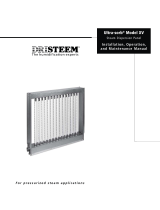
1. Remove the evaporating chamber
Remove the two fasteners on each side of
the cover enclosure (see figure below)
Remove the enclosure.
Do not remove the electrical panel cover
or heater terminal cover until electrical
power is disconnected. Safety first.
If the VAPORMIST has an SDU mounted
directly above it, the SDU cover must be
removed before removing the humidifier
cover.
If the tank is hot, cool it down by moving
the valve lever located on the back of the
drain valve to the manual open position –
the fill valve will eventually open allowing
cool water to run through the tank until it is
cool enough to handle.
Shut off the water supply.
Shut off the electrical supply.
Allow the tank to completely drain.
Disconnect the fill line at the supply side of
the fill valve.
Disconnect the electrical plugs between the
tank components and the back of the
electrical panel (includes: power plug, fill
plug, drain plug, water level control plug,
tank temperature sensor plug and thermal
trip plug). DISCONNECT BY PULLING ON
PLUG HOUSING. DO NOT DISCONNECT
BY PULLING ON CORD OR WIRES.
Disconnect the drain union on the back left
corner of the frame.
Disconnect the steam supply hose from the
top of the tank.
Lift the tank foot above the frame flange and
slide the tank assembly forward toremove.
Cover enclosure
screw cap detail
OM-778-3
VM99-C-0302.pdf 20 11/19/2009 9:51:32 AM
  • Page 1 1
  • Page 2 2
  • Page 3 3
  • Page 4 4
  • Page 5 5
  • Page 6 6
  • Page 7 7
  • Page 8 8
  • Page 9 9
  • Page 10 10
  • Page 11 11
  • Page 12 12
  • Page 13 13
  • Page 14 14
  • Page 15 15
  • Page 16 16
  • Page 17 17
  • Page 18 18
  • Page 19 19
  • Page 20 20
  • Page 21 21
  • Page 22 22
  • Page 23 23
  • Page 24 24
  • Page 25 25
  • Page 26 26
  • Page 27 27
  • Page 28 28
  • Page 29 29
  • Page 30 30
  • Page 31 31
  • Page 32 32

DriSteem VAPORMIST Specification

Category
Dehumidifiers
Type
Specification
This manual is also suitable for

Ask a question and I''ll find the answer in the document

Finding information in a document is now easier with AI