
C
VEHICLE MOUNTED AIR COMPRESSORS
VR70 UNDERHOOD
AIR COMPRESSOR
INSTALLATION MANUAL
System V900120
2015-2011 FORD F250-F550 6.7L DIESEL
www. .com


Installation Manual for VMAC
System V900120
2015-2011 Ford F250-F550 6.7L Diesel
General Information .......................................................................... 4
Before You Start ............................................................................ 4
Additional Requirements ............................................................... 4
Part 1: Warranty and System ID ...................................................... 5
Part 2: Preparing for Installation .................................................... 8
Part 3: Installing the Cooler, Bracket and Compressor ............... 13
3.1 Installing the Oil Cooler ........................................................... 13
3.2 Routing Battery Cables ............................................................ 14
3.3 Continuing Oil Cooler Installation ............................................ 16
3.4 Installing Main Bracket ............................................................ 18
3.5 Battery Cable and Relocated Battery Box ............................... 30
3.6 Washer Bottle .......................................................................... 35
3.7 Air Filter Box ............................................................................ 38
Part 4: Installing the Tank and Hoses ............................................ 48
4.1 Installing the Tank and Brackets ............................................. 48
4.2 Installing the Hoses ................................................................. 50
4.3 Adding Oil to the System ......................................................... 51
Part 5: Installing the Control Components .................................... 52
5.1 Installing the Components ....................................................... 53
5.2 Routing the In-cab Wiring ........................................................ 53
5.3 Connecting the In-cab Wiring .................................................. 53
5.4 Completing and Testing the Installation .................................. 55
5.5 Safety Test .............................................................................. 56
Part 6: Finishing the Installation ..................................................... 57
6.1 Before Starting the Engine Checklist ....................................... 57
6.2 After Starting the Engine Checklist .......................................... 57
6.3 Setup, Performance Testing and Adjustments ........................ 58
6.4 Auxiliary Air Receiver .............................................................. 59
Accessory Products from VMAC ..................................................... 60

VMAC – Vehicle Mounted Air Compressors
Toll Free: 1-888-241-2289
Fax: 1-250-740-3201
2
!
Document #1930165
Installation Manual for VMAC System V900120
2015-2011 Ford F250-F550 6.7L Diesel
Changes and Revisions
Version
Revision Details
Revised by/date
Checked by/date
Reviewed by/date
Implemented
H
ECN 13-102
CJH 07 Nov 2013
MH/DB 07 Nov 13
N/A
07 Nov 2013
J
ECN 14-018
JR 30 APR 2014
MH 06 May 2014
RD 06 May 2014
12 May 2014
K
ECN 18-135 Washer Btl
MSP 12 Jun 2018
KM/GB 12 Jun 2018
AWG 12 June 2018
13 June 2018
Important Information
This symbol is used to call your attention to instructions concerning
your personal safety. Watch for this symbol; it points out important
safety precautions, it means “attention, become alert! Your personal
safety is involved. Read the message that follows and be alert to
the possibility of personal injury or death. Be alert; your safety is
involved. While it is impossible to warn about every conceivable
hazard, let good common sense be your guide.
This symbol is used to call your attention to additional instructions
or special emphasis on a specific procedure.
The information in this manual is intended for certified VMAC installers
who have been trained in installation procedures and for people with
mechanical trade certification who have the tools and equipment to
properly and safely perform the installation. Do not attempt this
installation if you do not have the appropriate mechanical training,
knowledge and experience.
Follow all safety precautions for under hood mechanical work. Any
grinding, bending or restructuring operations for correct fit in modified
trucks must follow standard shop practices.
All hoses, tubes, and wires that are rerouted or shifted
during installation must be secure so that they do not
contact excessively hot areas or sharp edges. Where
possible, use rubber coated P-clips. Follow the routing
suggestions in this manual and cover all hoses with the
supplied plastic loom.
!

VMAC – Vehicle Mounted Air Compressors
Toll Free: 1-888-241-2289
Fax: 1-250-740-3201
3
These instructions are a general guide for installing this system on
standard production trucks and do not contain information for installation
on non-standard trucks. This system may not fit special order models or
those which have had other changes without additional modifications. If
you have difficulty with the installation, contact VMAC.
The VMAC warranty form is located at the back of this manual. This
warranty form must be completed and mailed or faxed to VMAC at the
time of installation for any subsequent warranty claim to be considered
valid.
To order parts, contact your VMAC dealer. Your dealer will ask for the
VMAC serial number, part number, description and quantity. To locate
your nearest dealer, call 1-888-241-2289.
Copyright 2018
All trademarks used in this manual are the property of the respective copyright holder.
The contents of this manual may not be reproduced in any form without the express written
permission of VMAC, 1333 Kipp Road, Nanaimo, BC V9X 1R3.
Printed in Canada

VMAC – Vehicle Mounted Air Compressors
Toll Free: 1-888-241-2289
Fax: 1-250-740-3201
4
General Information
Before You Start
Read this manual before attempting installation so that you can
familiarize yourself with the components and how they fit on the truck.
Identify variations for different model years and different situations that
are listed in the manual. Open the package, unpack the components and
identify them.
All fasteners must be torqued to specifications. Use manufacturers
torque values for OEM fasteners. Apply Loctite 242 or equivalent on all
engine-mounted fasteners. Torque values are with Loctite applied
unless otherwise specified.
STANDARD GRADE 8 NATIONAL COARSE THREAD
Size
1/4
5/16
3/8
7/16
1/2
9/16
5/8
¾
Foot-pounds (ft-lb)
9
18
35
55
80
110
170
280
Newton meter (N•m)
12
24
47
74
108
149
230
379
STANDARD GRADE 8 NATIONAL FINE THREAD
Size
3/8
7/16
1/2
5/8
¾
Foot-pounds (ft-lb)
40
60
90
180
320
Newton meter (N•m)
54
81
122
244
434
METRIC CLASS 10.9
Size
M8
M10
M12
M14
M16
Foot-pounds (ft-lb)
19
41
69
104
174
Newton meter (N•m)
25
55
93
141
236
Additional Requirements
Special Tools
Pneumatic fan wrench removal set (such as Lisle 43300) or a manual
fan pulley holder (such as KD3900)
OEM flywheel locking tool part number J42386.

VMAC – Vehicle Mounted Air Compressors
Toll Free: 1-888-241-2289
Fax: 1-250-740-3201
5
Hose Information
Depending on other installed equipment, it might be necessary to
move the air/oil separation tank from its intended location. The
hoses used in VMAC compressor systems have a specific inner
liner that is compatible with our compressor oil. Use of hoses
other than those supplied or recommended by VMAC may cause
compressor damage and may void your warranty. Please contact
VMAC for replacement hoses and further information.
Part 1: Warranty and System ID
□ Complete the warranty form. The VMAC warranty form is located at
the back of this manual. This warranty form must be completed and
mailed or faxed to VMAC at the time of installation for any
subsequent warranty claim to be considered valid.
System Identification and Operating Instructions
The System Identification Number Plate must be attached to the vehicle
at the time of installation. This plate provides information that allows
VMAC to assist in customer inquiries and ordering of parts.
□ Mark and drill two 7/64-inch holes in the top of the cross member in
front of the OEM air filter box. Secure the plate with supplied self-
tapping screws
□ Clean cross member beside the number plate and stick the VMAC
belt routing diagram to the cross member.
□ Apply battery warning label to driver side of primary cooling
reservoir.
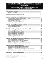
□ As part of the installation process, ensure that the safety and
operational instruction decal is affixed in an obvious location so that
it can be seen by vehicle operators. A good spot for this is usually
on the inside of the door or on the panel underneath the steering
wheel. (Figure 1.1).
!

VMAC – Vehicle Mounted Air Compressors
Toll Free: 1-888-241-2289
Fax: 1-250-740-3201
6
Figure 1.1

VMAC – Vehicle Mounted Air Compressors
Toll Free: 1-888-241-2289
Fax: 1-250-740-3201
7
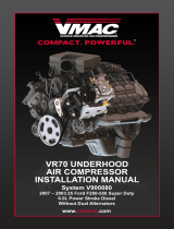
□ To alert any technicians that may service the vehicle, affix the
servicing caution/contact label in the engine compartment near the
hood latch in a visible location. Thoroughly clean the selected area
before affixing the label (figure 1.2)
Figure 1.2

VMAC – Vehicle Mounted Air Compressors
Toll Free: 1-888-241-2289
Fax: 1-250-740-3201
8
Part 2: Preparing for Installation
Preparation for installation is very important. Missing an item can cause
problems in the installation or even damage to components. Check off
each item as it is completed so that you do not miss any preparation
steps.
Ensure that you have filled out the VMAC Warranty
Registration. Install the System Identification Number
Plate and Operational Instruction Decal. (Please see Part 1
for details).
□ Locate the blunt-cut OEM SEIC wire harness, on the driver’s
side just below the OBDII port. You will need to find the transmission
park signal, (blue with grey stripe wire).
□ Use a multi-meter to verify the transmission park signal. Turn the
key to the IGN2 position, (do not start the truck), as to supply power
to the dash display. The resistance should read close to 0-ohms in
park and open circuit in all other gears. If this is correct, put the car
in park and turn the key to the off position.
There are multiple blue wires with various coloured stripes. The
transmission park signal needs to be electrically verified with a
multi-meter to ensure the correct wire is read.
□ Mark transmission park signal wire for connection later in installing
control components section.
□ Disconnect batteries, (both driver and passenger side).
□ Drain coolant from both the primary and secondary radiators, (drain
for primary coolant on driver’s side, secondary coolant on passenger
side). Start with the secondary radiator, (drain on passenger side).
Save coolant to be reused later. Close drain caps when coolant has
been drained.
□ Remove passenger side battery bracket and battery.

VMAC – Vehicle Mounted Air Compressors
Toll Free: 1-888-241-2289
Fax: 1-250-740-3201
9
□ Disconnect and remove the mass air flow sensor from the top of the
filter box. Keep sensor as it will be reinstalled into supplied air box
lid.
□ Remove filter box, (both upper and lower sections).
□ Remove bracket that holds the lower section of the filter box.
Discard bracket and bolts.
□ Remove tube and resonator that connects the filter box to the turbo
intake.
□ Cover turbo intake.
□ Remove passenger side hood strut and hood strut ball stud from the
hood, (save for later use).
□ Remove lower hood strut ball stud from inner fender.
□ Remove positive terminal block and wiring connector panel from
passenger side battery box. To remove wiring panel pry up.
Positive terminal block has one clip and slides up to remove.
□ Disconnect windshield washer tube from joint above passenger side
battery box on top of firewall.
□ Unplug wiring harness from windshield washer pump and remove
wiring from front lower passenger side battery box.
□ Unplug glow plug module connectors from bottom of passenger side
battery box, (3 connectors).
□ Remove the bolt from wheel well that secures inner fender to battery
box, (save for later use).
□ Remove passenger side battery box.

VMAC – Vehicle Mounted Air Compressors
Toll Free: 1-888-241-2289
Fax: 1-250-740-3201
10
□ Remove glow plug module from bottom of passenger side battery
box, (Torx T30 bolts), (Save module for later use).
□ Disconnect hoses from secondary coolant reservoir, (attached to
passenger side of fan shroud), and remove reservoir from fan
shroud.
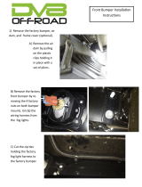
□ Remove upper secondary coolant hose, (top hose going to water
pump on passenger side of engine).
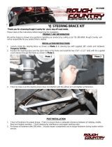
□ Cut plastic cuff securing hose on secondary rad hose carefully to
preserve fitting, (discard band and hose), (Figure 2.0.1).
Cut Plastic Cuff To
Remove Connector
Upper Secondary
Radiator Hose
Figure 2.0.1
□ Install supplied hose back on connector and secure with supplied
hose clamp, (Figure 2.0.2).
Supplied Hose
OEM Quick
Connect
Supplied Hose
Clamp
Figure 2.0.2

VMAC – Vehicle Mounted Air Compressors
Toll Free: 1-888-241-2289
Fax: 1-250-740-3201
11
□ Install hose coupling and flexible hose to open end of modified
secondary coolant hose. Leave about 1” gap between hoses and
secure with supplied hose clamps.
□ Remove plastic wire guide from front of EGR on passenger side of
engine (two bolts securing to EGR and plastic ties securing to wire).
Discard bolts and plastic. (Figure 2.3).
Figure 2.3
□ Using knife cut insulated heat shield if required to clear hose.
Install modified hose back on secondary water pump. Ensure
notches on OEM quick connector align with notches on secondary
water pump. Point elbow towards rear of truck (opposite to the
original direction). Ensure hose is not kinked. (Rotate the hose on
the OEM quick connect, if required this will remove kinks). Hose
must run underneath the injector wiring harness.
□ Ensure OEM locking clip is engaged on plastic elbow. Loop hose
towards front of truck.
□ Remove bolt securing power steering reservoir to upper fan shroud.
DO NOT remove hose from reservoir. Slide reservoir up out of clip
securing it to the upper fan shroud.

VMAC – Vehicle Mounted Air Compressors
Toll Free: 1-888-241-2289
Fax: 1-250-740-3201
12
□ Remove 5 bolts (3 on driver’s side and 2 on passenger side) and
wire clips securing upper fan shroud and remove upper fan shroud
from truck.
□ Unplug fan wire (unplug connector closer to the engine, not the one
right on the hub of the fan). Remove long bolt securing fan wiring
harness to engine and discard.
□ Remove the fan (right-hand thread) and pull it out of the engine bay.
For ease of fan removal and installation, it is recommended
that a pneumatic fan wrench removal set (such as Lisle 43300)
or a manual fan pulley holder (such as KD3900) is used.
□ Remove fan stator (the lower shroud can be left in place if the stator
is rotated to clear the lower lip).
□ Remove upper passenger side fan stator mount and save for use
later.
□ Release tension on OEM belt (leave belt routed correctly on
passenger side of engine).
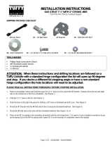
□ Remove 2 bolts from secondary water pump, (Figure 2.4).
Remove OEM Bolts From
Secondary Water Pump
Figure 2.4

VMAC – Vehicle Mounted Air Compressors
Toll Free: 1-888-241-2289
Fax: 1-250-740-3201
13
Part 3: Installing the Cooler,
Bracket and Compressor
3.1 Installing the Oil Cooler
□ Remove lower primary coolant hose, (attached to the primary cooler
and engine), (Figure 3.1).
To
Engine
From
Radiator
Figure 3.1
□ Cut the plastic cuff securing the OEM quick connect to engine side
coolant hose, (discard OEM quick connect), (Figure 3.2).
Cut Cuff
OEM Quick
Connect
Figure 3.2
□ Cut the radiator side coolant hose 8” from the OEM quick connect,
(discard short section of hose with OEM quick connect),
(Figure 3.3).

VMAC – Vehicle Mounted Air Compressors
Toll Free: 1-888-241-2289
Fax: 1-250-740-3201
14
OEM Quick
Connect
Discard This
Section
8”
Figure 3.3
3.2 Routing Battery Cables
□ Apply loom to supplied battery cable extensions.
Note: The red and the black battery cables will follow the same
route!
□ Route the supplied positive/red battery cable between the frame and
body from the re-located battery location that will be under the driver
side. Leave 20” of cable to the rear of the body mount hanging
under driver side door.
□ Continue routing the cable above the truck electrical harness and
below the two metal power steering lines.
□ Continue routing, careful to avoid the steering column, around front
of the steering box until the cable reaches the electrical harness
under/beside the fan shroud.
□ Feed cable along fan shroud following other truck wiring harness.
□ Continue following truck wiring harness under the air intake and
metal bracket. Route along the inner fender plastic wire guide tray
under fender and follow OEM positive cable wire harness to
relocated battery positive terminal.

VMAC – Vehicle Mounted Air Compressors
Toll Free: 1-888-241-2289
Fax: 1-250-740-3201
15
□ Route the negative battery cable from the relocated battery location
and follow the positive battery cable. Continue routing under the fan
shroud, and, in such a way it will remain clear of the crank pulley
and any other sharp or moving objects.
□ Remove the OEM negative battery block bolt attaching the OEM
negative battery cable located beside the engine side coolant OEM
quick connect, (Figure 3.4).
For ease of removal the OEM negative battery block bolt
should be removed with the engine side coolant hose
disconnected. Figure 3.4 shown with coolant hose connected
to illustrate the OEM negative battery bolt location.
OEM Negative
Battery Engine
Block Bolt
Engine Side
Coolant Hose
Front of
Engine
Figure 3.4
□ Install the supplied negative battery cable lug on top of the existing
OEM negative battery cable lug. Orientate the cable so that it travels
down and under the existing vehicle battery tray facing the front of
the vehicle towards the fan shroud. Reuse the existing OEM
negative battery bolt.
□ Secure battery cables with tie-straps as required as to clear the
crank pulley and other moving parts.

VMAC – Vehicle Mounted Air Compressors
Toll Free: 1-888-241-2289
Fax: 1-250-740-3201
16
3.3 Continuing Oil Cooler Installation
Do not strike the impact sensor as this could cause the airbags
to actuate.
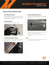
□ Position the cooler in the center of the cross-member so that it is
just above the sway bar with the oil ports facing up, (Figure 3.5).
Fog Light Connector
Location
Impact Sensor
Location
Cross Member
Figure 3.5
□ Apply Loctite then install bolts through the flat mounting strap and
place them on the front of the cross member on each side of the
impact sensor. Note the impact sensor is located in the center of the
cross-member; the driver side wire connection is for the fog lights if
equipped, (Figure 3.5).
□ Thread the bolts into the matching holes on the cooler mounts hand
tight only, this will allow the cooler to be repositioned if necessary
after the coolant hoses have been reattached, (Figure 3.5).
□ Install the radiator side coolant hose and secure with supplied hose
clamp, (Figure 3.6).
!

VMAC – Vehicle Mounted Air Compressors
Toll Free: 1-888-241-2289
Fax: 1-250-740-3201
17
Figure 3.6
□ With the radiator side coolant hose secured tighten the cooler mount
bolts to specification.
□ Install the engine side coolant hose and secure with supplied hose
clamp, (Figure 3.6). Note it may be necessary to trim the cooler end
of the coolant hose, do so as required if any kinking of the hose
occurs.
□ Apply hose protection to 1/2" oil hoses.
□ Connect the shortest 1/2" hose to the passenger side of the cooler
and orient as shown, (Figure 3.7).
□ Connect the longest 1/2" hose to the driver side of the cooler and
orientate as show, (Figure 3.7). (Note the cooler hoses must be
installed before the fan shroud is installed).
Figure 3.7

VMAC – Vehicle Mounted Air Compressors
Toll Free: 1-888-241-2289
Fax: 1-250-740-3201
18
For ease of installation the cooler hoses should be installed after
the cooler is installed and before the fan and upper fan shroud
are installed.
3.4 Installing Main Bracket
□ Remove tensioner and idlers from VMAC bracket.
□ Disconnect A/C sensor.
□ Install supplied adhesive rubber pad on the air conditioning line that
runs in front of the modified upper secondary coolant hose
connector (at the water pump). Install adhesive rubber pad to
protect hose where it will rub against main bracket. Secure with zip
ties.
□ Remove Stud Bolt at front, passenger side engine cover, and cut off
stud flush to top of bolt head, then reinstall bolt. (Figure 3.8).
□ Install main bracket. On single alternator trucks use supplied
spacers behind top drivers side mount and lower front mount
between bracket and secondary water pump, (Figure 3.9).
For ease installation you may want to remove lower secondary
rad hose to get main bracket in place on engine. Reinstall hose
immediatly after installation of bracket.
Secondary coolant hose routes under compressor pad. Ensure
hose does not kink. Adjust hose clamps if necessary.
The wiring harness is routed above the VMAC bracket and the
front of the engine and specific attention must be paid to
ensuring the wiring harness is not pinched.
□ Check to make sure that no wires or OEM objects are pinched
between the bracket and the engine. The coolant hose installed
earlier must run under compressor platform.
Page is loading ...
Page is loading ...
Page is loading ...
Page is loading ...
Page is loading ...
Page is loading ...
Page is loading ...
Page is loading ...
Page is loading ...
Page is loading ...
Page is loading ...
Page is loading ...
Page is loading ...
Page is loading ...
Page is loading ...
Page is loading ...
Page is loading ...
Page is loading ...
Page is loading ...
Page is loading ...
Page is loading ...
Page is loading ...
Page is loading ...
Page is loading ...
Page is loading ...
Page is loading ...
Page is loading ...
Page is loading ...
Page is loading ...
Page is loading ...
Page is loading ...
Page is loading ...
Page is loading ...
Page is loading ...
Page is loading ...
Page is loading ...
Page is loading ...
Page is loading ...
Page is loading ...
Page is loading ...
Page is loading ...
Page is loading ...
Page is loading ...
Page is loading ...
Page is loading ...
Page is loading ...
Page is loading ...
Page is loading ...
-
 1
1
-
 2
2
-
 3
3
-
 4
4
-
 5
5
-
 6
6
-
 7
7
-
 8
8
-
 9
9
-
 10
10
-
 11
11
-
 12
12
-
 13
13
-
 14
14
-
 15
15
-
 16
16
-
 17
17
-
 18
18
-
 19
19
-
 20
20
-
 21
21
-
 22
22
-
 23
23
-
 24
24
-
 25
25
-
 26
26
-
 27
27
-
 28
28
-
 29
29
-
 30
30
-
 31
31
-
 32
32
-
 33
33
-
 34
34
-
 35
35
-
 36
36
-
 37
37
-
 38
38
-
 39
39
-
 40
40
-
 41
41
-
 42
42
-
 43
43
-
 44
44
-
 45
45
-
 46
46
-
 47
47
-
 48
48
-
 49
49
-
 50
50
-
 51
51
-
 52
52
-
 53
53
-
 54
54
-
 55
55
-
 56
56
-
 57
57
-
 58
58
-
 59
59
-
 60
60
-
 61
61
-
 62
62
-
 63
63
-
 64
64
-
 65
65
-
 66
66
-
 67
67
-
 68
68


Vmac V900120 Installation guide
- Type
- Installation guide
- This manual is also suitable for
Ask a question and I''ll find the answer in the document
Finding information in a document is now easier with AI
Related papers
-
 Vmac V90G120 Installation guide
-
 Vmac V910010 Installation guide
-
 Vmac V900130 Installation guide
-
 Vmac V910017 Installation guide
-
 Vmac V900113 Installation guide
-
 Vmac V900126 Installation guide
-
Vmac V900103 Installation guide
-
 Vmac V900099 Installation guide
-
 Vmac V910006 Installation guide
-
 Vmac V900080 Installation guide


Other documents
-
 Quadratec FB21015 Installation guide
-
 JCR Offroad XJLM50-PC Installation guide
-
 Rough Country 1154 Installation guide
-
 Crown Automotive RT20014 Installation guide
-
 DV8 OFFROAD FBSHTB-16 Installation guide
-
 MISHIMOTO MMFAN-16 Installation guide
-
 Tuffy 292-01 Installation guide
-
 Tuffy 863 Installation guide
-
 Warrior Products 897 Installation guide
-
 Rugged Ridge 11252.51 Installation guide


