Page is loading ...

MICRO-EPSILON MESSTECHNIK GmbH & Co. KG
Koenigbacher Str.15
94496 Ortenburg / Germany
Tel. +49 8542 / 168-0 / Fax +49 8542 / 168-90
e-mail [email protected]
www.micro-epsilon.com
Assembly Instructions
IF2008/ETH
X9771379-A012090HDR
*X9771379-A01*
Pin Assignment
Connector Pin Signal Remarks
1
1 Ethernet TxD+ -
2 Ethernet RxD+ -
3 Ethernet TxD- -
4 Ethernet RxD- -
Pin assignment of Ethernet interface
Connector Pin Function Remarks
2
1 +24 VDC
1
Power supply for
interface module and
sensors
2 +24 VDC
1
3 GND
4 GND
5 Shield
Pin assignment of power connection
1) Permissible supply voltage range 11 - 30 V
Connector Pin Function Remarks
3
1 External entrance 1 -
2 External entrance 2 -
3 External entrance 3 -
4 External entrance 4 -
5 External output 1 -
6 External output 2 -
7 External output 3 -
8 External output 4 -
9 n.c. -
10 n.c. -
11 Voltage output
LLL = +5 V,
HLL = +24 V
12 GND -
Pin assignment I/O interface
Connector Pin Signal IF2008 ETH Signal Encoder
4a
4b
4c
4d
4e
4f
4g
4h
1 A+ A+
2 A- A-
3 B+ B+
4 B- B-
5 R+ R+
6 R- R-
7 +24 VDC
1
n.c.
8 Laser ON-
1
n.c.
9 Multi-function output
1
n.c.
10 ERROR input
1
n.c.
11 +5 VDC +5 VDC
12 GND GND
Pin assignment encoder interface
1) Only for sensors
Connector Pin Signal
IF2008 ETH
Signal
ILD 1420
Signal
ILD 2300
Signal
IFC 24xx
4a
4b
4c
4d
4e
4f
4g
4h
1 TRG+ n.c. TRG+ n.c.
2 TRG- n.c. TRG- n.c.
3 TxD+ RxD+ RxD+ TxD+
4 TxD- RxD- RxD- TxD-
5 RxD+ TxD+ TxD+ RxD+
6 RxD- TxD- TxD- RxD-
7 +24 VDC +U
B
+U
B
and
Laser ON+
n.c.
8 Laser ON- Laser ON- Laser ON- n.c.
9 Multifunction
output
Multifunction
input
n.c. TRG+
(HLL)
1
10 ERROR
input
ERROR
output
n.c. n.c.
11 + VDC (only
for encoder)
n.c. n.c. n.c.
12 GND GND GND GND
Pin assignment for sensor interface
1) Bridge for HLL level is set on the IFC 24xx controller.
You can download a PDF of the detailed operating instructions from our
website:
www.micro-epsilon.de/download/manuals/man--IF2008-ETH--en.pdf

Intended Use
The IF2008 ETH interface module is designed for use in industrial and labo-
ratory applications. It is used to convert the MICRO-EPSILON internal sensor
protocol (RS422) to Ethernet.
The IF2008 ETH interface module must only be operated within the limits
specified in the technical data. The IF2008 ETH interface module must be used
in such a way that no persons are endangered or machines and other material
goods are damaged in the event of malfunction or total failure of the IF2008
ETH interface module. Take additional precautions for safety and damage
prevention in case of safety-related applications.
Warnings
Connect the power supply and the display/output device according to the
safety regulations for electrical equipment.
> Risk of injury, damage to or destruction of the interface module
The supply voltage must not exceed the specified limits.
> Risk of injury, damage to or destruction of the interface module
Avoid shocks and impacts to the interface module.
> Damage to or destruction of the interface module
Notes on CE Marking
The following apply to the IF2008 ETH interface module:
- EU Directive 2014/30/EU
- EU Directive 2011/65/EU, “RoHS”
Products which carry the CE mark satisfy the requirements of the EU directives
cited and the relevant applicable harmonized European standards (EN). The
measuring system is designed for use in industrial environments and laborato-
ry applications.
The EU Declaration of Conformity is available to the responsible authorities
according to EU Directive, article 10.
Proper Environment
Protection class: IP65 (When all plugs are connected.)
- Temperature range:
Operation: 0 ... +50 °C (+32 ... +122 °F)
Storage: +5 ... +50 °C (+41 ... +122 °F)
- Humidity: 5 - 95 % (non-condensing)
- Ambient pressure: Atmospheric pressure
Installation and Assembly
i
Ensure careful handling during installation and operation.
120 (4.7)
150.5 (5.9)
155.5 (6.1)
171 (6.7)
204 (8)
220 (8.66)
35 (1.38) 50 (1.97)
75 (2.95) 17.1
(.67)
7
(.27)
50 (1.97) 50 (1.97)
2.50 (.1)
40 (1.57)20 (.79) 40 (1.57)
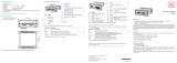
Dimensional drawings
IF2008 ETH interface
module, dimensions in mm
(inches), not to scale
Pin Assignment
LEDs
LED LED
color
Description
1
2
2
3
1
Off Power supply off
Green Interface module is
ready for operation
Orange Interface module is in
bootloader/flash mode
Red Initialization of the inter-
face module
2
Off No Ethernet connection
Orange Connection between PC
and interface module
(100 Mbps)
Flashing Data transmission be-
tween PC and interface
module
3
Off No sensor/encoder
selected
Green Interface set for sensor
Orange Interface set for sensor
Description of status LEDs IF2008 ETH interface module
Connector Overview
21
3
4a 4b
4c 4d
4e
4f
4g
4h
Plug-in connections IF2008 ETH interface modul
Connector Description
ETH Flange socket, 4-pin, type Binder 09 3732 500 04 for
Ethernet connection
POWER Flange connector, 5-pin, type Binder 09 3441 600 05 for
power connection
I/O Flange connector, 12-pin, type Binder 09 3491 600 12 for
power connection
CH1 - CH8 Flange socket, 12-pin, type Binder 09 3492 600 12 for
sensor/encoder connection
Overview of plug-in connections
/