14
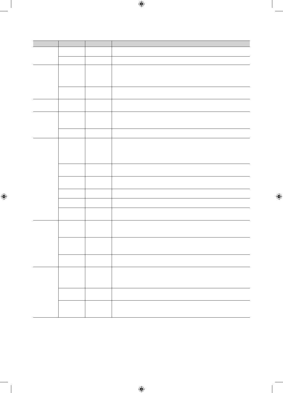
Menu Item initial Value Description
Menu OSD
Picture Menu
Lock
OFF
Enable or disable the Picture Menu.
Menu Display ON
y On : The Main Menu is displayed.
y Off : The Main Menu is not displayed.
Operation
Panel Button
Lock
Unlock
Turning the front panel (local key) operations on/off.
y Unlock : Unlocks all panel keys.
y Lock : Locks all panel keys.
y OnlyPower : Locks all panel keys except the Power panel key.
y Menu/Source : Locks the Menu and Source panel keys.
Mute on CC OFF
y On : Closed Captions are automatically displayed when Mute is on.
y Off : To turn off Closed Captions (when Mute is on), press the CC key on the remote
control or Pillow Speaker.
Clock Local Time Manual
Select the way to update clock data.
Use clock data from a DTV channel to set the clock automatically or set the clock manually when
the TV is in stand-alone mode.
Music Mode
Music Mode
AV
OFF
Allows music output from an mp3/audio player connected to an AV Input Source on the TV.
When on, you can hear sound from the player through the TV whether there is a video signal or
not. Also mutes the video so the TV does not display a picture when a guest is playing music.
The TV's backlight, however, remains on.
Music Mode
Backlight
OFF
When set to Off, the TV's backlight is turned off entirely when a guest uses the Music mode. To
save energy, set to Off.
External
Device
7610 Priority
AV
1
Lets you set the priority of the 7610 RJP AV jack. You can choose 1, 2, or 3, with 1 being the
highest and 3 the lowest. The TV automatically displays the source with the higher priority. For
example, lets say AV is set to 1 and HDMI is set to 2. If a guest has attached a device to the
HDMI jack, and then plugs a device into the AV jack, the TV will automatically switch to the device
plugged into the AV jack (the jack with the higher priority). Note that a guest can also switch
devices manually by pushing a button on the 7610 RJP.
7610 Priority
PC
2
Lets you set the priority of the 7610 RJP PC jack. You can choose 1, 2, or 3, with 1 being the
highest and 3 the lowest. The TV automatically displays the source with the higher priority. See
above for a more detailed explanation.
7610 Priority
HDMI
3
Lets you set the priority of the 7610 RJP HDMI jack. You can choose 1, 2, or 3, with 1 being the
highest and 3 the lowest. The TV automatically displays the source with the higher priority. See
above for a more detailed explanation.
7610 AV
Option
AV
Select which AV source of the TV is connected to the RJP jack.
RJP HDMI
Option
HDMI1
Select which HDMI source of the TV is connected to the RJP jack. (HDMI1/HDMI2/HDMI3)
HDMI Music
Mode
OFF
Allows music output from an mp3/audio player connected to an HDMI Input Source. When on,
you can hear sound from the player through an HDMI input of the RJP whether there is a video
signal or not. (This option is only compatible with the Guest link RJP.)
External
Source
USB Media
Mode
Default
When a USB device is connected to the TV :
y Default : A popup window appears.
y Automatic : Opens the USB contents menu automatically.
y Disable : Neither the popup window nor the menu appears.
External
Source
Banner
ON
If set to On, the TV displays the External Source Banner (information) when you change the TV
source to another external input, press the Info key, or turn the TV on.
y On : The External Source information is displayed on the TV screen.
y Off : The External Source information is not displayed on the TV screen.
Auto Source OFF
y On : When an external input source is connected to the TV, the TV identifies the input
source, and then automatically switches to that input source.
y Off : Auto Source function is Off.
Pillow
Spekaer
Pillow Spekaer
Type
CZ
Select the type of Pillow Speaker.
You must select the type of Pillow Speaker currently connected for it to operate properly.
y CZ : the type of Zenith IR Code and 12V Vcc
y CP : the type of Philips IR Code and 5V Vcc
y CS : the type of Samsung IR Code and 12V Vcc
Speaker
Select
Main
Select the speaker where the TV sound is outputted.
y Main : The TV sound is outputted in all of the TV speaker and Pillow Speaker.
y External : The TV sound is outputted in Pillow Speaker only.
Pillow Volume OFF
You can control the volume level of Pillow Speaker.
y High : The volume level of Pillow Speaker is high.
y Normal : The volume level of Pillow Speaker is normal.
y Low : The volume level of Pillow Speaker is low.
[HG673-ZA]Install Guide-ENG.indd 14 2013-03-07 �� 10:59:29