Samsung HG46NB690QF User manual

Category
LED TVs
Type
User manual
imagine the possibilities
Thank you for purchasing this Samsung product.
To receive more complete service, please register
your product at
www.samsung.com/register
Model Serial No.
LED TV
Installation manual
[HG690_ZA]Install_Guide_00ENG.indd 1 2013-03-20  9:02:01
Figures and illustrations in this User Manual are provided for reference only and may differ from actual product appearance.
Product design and specifications may be changed without notice.
Introduction
This TV has functionality that lets it interact with a set-back box (SBB/STB) and with other TVs in a computer-controlled system for hotels and
other hospitality businesses.
Interactive : When the TV is powered-up initially, it sends a command to identify the connected SBB/STB. If it identifies the SBB/STB, the TV switches to
ONLINE mode which gives full control of the TV to the SBB/STB.
When the TV is in ONLINE mode, it stops accepting IR (Samsung remote) commands and acts according to the interface protocol.
Stand-Alone: If you are not using an SBB/STB and the TV cannot or does not identify an SBB/STB, you should switch the TV to STAND-ALONE mode
with restricted operation.
Operational Modes
When this TV is in Hotel mode and is operated with an SBB/STB, it is in one of two states: ONLINE or STAND-ALONE
• In the STAND-ALONE state, the TV will act as a Hotel TV, but without active communication. This is to prevent guests from trying to cheat the system
by disconnecting the SBB/STB.
To set the options for Stand-alone or Interactive (Online) mode, refer to pages 19-23 (Setting the hotel option data : Menu Items.)
• You can restrict all (or some) operations to prevent guests from "cheating" the TV system.
• You can can set Volume limits and lock or unlock the Panel buttons.
Still image warning
Avoid displaying still images (such as jpeg picture files) or still image elements (such as TV channel logos, panorama or 4:3 format images, stock or news
bars or crawls) on the screen. Displaying still pictures continually can cause uneven screen wear, which will affect image quality. To reduce the chance that
this effect will occur, please follow the recommendations below:
• Avoid displaying the same TV channel for long periods.
• Always try to display a full screen image.
• Reduce brightness and contrast to help to prevent the occurrence of after-images.
• Use all TV features designed to reduce image retention and screen burn-in. Refer to the proper user manual section for details.
Ensuring Proper Ventilation
When you install the TV, maintain the distances shown below between the TV and other objects ((walls, cabintet sides, etc.) to ensure proper ventilation.
Failing to do so may result in a fire or problems with the TV caused by an increase in its internal temperature.
When using a stand or wall-mount, use parts provided by Samsung Electronics only.
x
If you use parts provided by another manufacturer, it may cause a problem with the product or cause the product to fall, leading to serioius injury.
Installation with a stand. Installation with a wall-mount.
4 inches4 inches
4 inches
4 inches4 inches
4 inches
4 inches
Additional Information
The appearance of the TV and its accessories may differ from the illustrations in this manual, depending on the TV.
Be careful when you touch the TV if it is on or has been on for a period of time. Some parts can be hot.
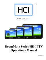
Power
ON
Online Mode
Poll Rate 20/sec
Stand-alone
Mode
SBB/STB Online if one success
within 10 attempts
SBB/STB
Online-10
consecutive fails
SBB/STB Status-Attempt
every 2 seconds
[HG690_ZA]Install_Guide_00ENG.indd 2 2013-03-20  9:02:01
3
Contents
ENGLISH
English
Symbols Used in this Manual
t
Indicates that you can press the
TOOLS button on the remote control
to use this function.
Note One-Touch Button
TOOLS
y Introduction .............................................................................................................................................................. 2
y Operational Modes ................................................................................................................................................... 2
y Still image warning .................................................................................................................................................... 2
y Ensuring Proper Ventilation ...................................................................................................................................... 2
y Additional Information ............................................................................................................................................... 2
y Accessories .............................................................................................................................................................. 4
y Installing the LED TV Stand ....................................................................................................................................... 5
y Assembling the swivel (32 inch TVs or larger) ............................................................................................................ 7
y Using the TV's Controller .......................................................................................................................................... 8
y The Connection Panel ............................................................................................................................................... 9
y The Remote Control ................................................................................................................................................ 11
y Connecting to the Network ..................................................................................................................................... 12
y Connecting the TV to an SBB or STB ..................................................................................................................... 14
y Connecting the Bathroom Speakers ....................................................................................................................... 17
y Connecting the RJP (Remote Jack Pack) ................................................................................................................ 18
y Setting the Hotel Option Data ................................................................................................................................. 20
y Installing the Wall Mount ......................................................................................................................................... 40
y Anti-theft Kensington Lock ...................................................................................................................................... 42
y Specifications ......................................................................................................................................................... 43
y Display Resolution................................................................................................................................................... 44
y Dimensions ............................................................................................................................................................. 45
[HG690_ZA]Install_Guide_00ENG.indd 3 2013-03-20  9:02:01
4
English
Accessories
Please make sure the following items are included with your LED TV. If any items are missing, contact your dealer.
The items’ color and shape may vary, depending on the model.
The parts for the stand are listed under Stand Components on the following page.
y Remote Control (AA59-00817A) & Batteries (AAA x 2) y Hotel Mount Kit
y Owner’s Instructions
y Power Cord
y Safety Guide / Quick Setup Guide
(Not available in all locations)
y Data Cable (BN39-00865B)
4 EA (M4 X L12)
y Security Screws
Requires 5/32" tamper resistant hex wrench. (Sold
separately)
y HOLDER RING (46" (2ea) / 55" (4ea))
[HG690_ZA]Install_Guide_00ENG.indd 4 2013-03-20  9:02:01
5
English
Installing the LED TV Stand
The 32” and larger LED TVs have swivel stands. You can set these stands so that the TVs swivel 20 degrees left and right. 60
degrees left and right, or 90 degrees left and right. See page 7.
Components
When installing the stand, use the provided components and parts.
A
1 EA
B
1 EA
C
x8 (M4 X L12)
D
x8 (M4 X L10)
y S
tand
(Stand shape is depending on the model)
y Guide Stand y Screws
NOTE
y Make sure to distinguish between the front and back of the Stand and Stand Guide when connecting them.
y Make sure that at least two people lift and move the TV.
y When connecting the stand, lay the product down on a soft surface, with the screen facing down, and then fasten the
screws.
4
Place a soft cloth over the table to protect the TV, and then
place the TV on the cloth screen-side down.
Insert the Stand Guide into the slot of TV bottom side.
1 2
B
A
Rear
Front
(Incorrect assembly)
Side View
3
(Correct assembly)
Top View
DO NOT USE
CHEMICALS
DO NOT USE
GREASE
DO NOT USE
OIL
ATTENTION
C
x4 (M4 X L12)
D
x4 (M4 X L10)
or
D
(M4 X L12, SECURITY)
x4
C
(M4 X L12)
x4
[HG690_ZA]Install_Guide_00ENG.indd 5 2013-03-20  9:02:03
6
English
¦ Hotel Mount Kit
Affix the stand to a flat surface such as a
dresser top, desk top, or entertainment center as
shown.
Short Bolt (2EA) Long Bolt (2EA) Nut (2EA) Washer (2EA)
Bolt + Nut
Top
Bottom
[HG690_ZA]Install_Guide_00ENG.indd 6 2013-03-20  9:02:04
7
English
Assembling the swivel (32 inch TVs or larger)
] WARNING: If you configure the TV to swivel, you must attach it securely to the floor, a desk, a dresser top, etc. as
described in the installation instructions.
The 32” and larger LED TVs have swivel stands. You can configure these stands so that the TVs swivel 20 degrees left and
right, 60 degrees left and right, or 90 degrees left and right using the BRACKET HOLDER SWIVEL.
¦ 20° swivel
To configure the TV so that it swivels 20° left and right, insert the prong on the bottom of the stand through the curved hole
in the Bracket Holder Swivel marked 20°. Then, fix the Bracket Holder Swivel to the stand using the three supplied screws as
shown to the left.
¦ 60° swivel
To configure the TV so that it swivels 60° left and right, insert the prong on the bottom of the stand through the curved hole
in the Bracket Holder Swivel marked 60°. Then, fix the Bracket Holder Swivel to the stand using the three supplied screws as
shown to the left.
¦ 90° swivel
To configure the TV so that it swivels 90° left and right, remove the Bracket Holder Swivel, and then screw the three supplied
screws into the stand as shown to the left.
[HG690_ZA]Install_Guide_00ENG.indd 7 2013-03-20  9:02:05
8
English
Using the TV's Controller
The color and shape of the TV Controller may vary depending on the model.
The TV's Controller, a small joy stick like button on the bottom right side of the TV, lets you control the TV without the
remote control.
Power on Turn the TV on by pressing the Controller when the TV is in standby mode.
Adjusting the volume Adjust the volume by moving the Controller from side to side when the
power is on.
Selecting a channel Select a channel by moving the Controller backwards and forwards when
the power is on.
Using the Function menu To view and use the Function menu, press and release the Controller
when the power is on. To close the Function menu, press and release the
Controller again.
Selecting the MENU (
m
)
With the Function menu visible, select the MENU (
m
) by moving the
Controller to the left. The OSD (On Screen Display) Menu appears. Select an
option by moving the Controller to the right. Move the Controller to the right
or left, or backwards and forwards to make additional selections. To change
a parameter, select the it, and then press the Controller.
Selecting SMART HUB (
) With the Function menu visible, select SMART HUB () by moving the
Controller upwards. The SMART HUB main screen appears. Select an
application by moving the Controller, and then pressing the Controller.
Selecting a Source (
s
) With the Function menu visible, open the Source screen (
s
) by pushing
the Controller to the right. The Source screen appears. To select a
source, move the Controller back and forth. When the source you want is
highlighted, press the Controller.
Power Off (
P
) With the Function menu visible, select Power Off (
P
) by pulling the
Controller forwards, and then press the Controller.
To close the Menu, SMART HUB, or Source, press the Controller for more than 1 second.
Standby mode
Your TV enters Standby mode when you turn it off, and continues to consume a small amount of electric power. To be safe
and to decrease power consumption, do not leave your TV in standby mode for long periods of time (when you are away on
vacation, for example). It is best to unplug the power cord.
mR
P
TV Controller
The control stick is located at the lower-left
corner on the back of the TV.
Turn off the TV.
Open Smart Hub.
Open the menu.
Select a source.
Remote control sensor
When you use the Remote control, the
standby LED does not respond, except
when you press the
P
button.
[HG690_ZA]Install_Guide_00ENG.indd 8 2013-03-20  9:02:06
9
English
The Connection Panel
Whenever you connect an external device to your TV, make sure that power on the TV and the device is turned off.
When connecting an external device, match the color of the connection terminal to the cable.
1 HDMI IN 1(DVI), 2, 3, 4 (ARC): Connects to the HDMI jack of a device with an HDMI output.
No sound connection is needed for an HDMI to HDMI connection. HDMI connections carry both audio and video.
Use the HDMI IN 1(DVI) jack for a DVI connection to an external device. Use a DVI to HDMI cable or DVI-HDMI
adapter (DVI to HDMI) for the video connection and the PC/DVI AUDIO IN jacks for audio.
2 DVI AUDIO IN: Connects to the audio output jack on your PC.
3 AUDIO OUT: Connects to the audio input jacks on an Amplifier/Home Theater.
4 VARIABLE AUDIO OUT: Used for the audio output to the Bathroom speaker. Connect the Bathroom Wall Box and the
Variable port (RCA).
5 VOL-CTRL: Used to control the volume of the Bathroom speaker. Connect the Bathroom Wall Box and the VOLCTRL port.
6 COMPONENT IN / AV IN / AV IN 2
Use to connect to Component video / audio devices such as DVD players and AV (Composite) devices such as VCRs.
Connect audio cables to "R-AUDIO-L" on your TV and the other ends to corresponding audio out jacks on A/V or
Component devices.
The COMPONENT IN jack is also used as the VIDEO 1 jack.
Connect component video cables (not supplied) to the component jacks ("P
R", "PB", "Y") on the rear of your TV and the
other ends to corresponding component video out jacks on a DVD player. Match the colors on the jacks and cables.
If you want to connect both a Set-Top Box and a DVD player, you should connect the Set-Top Box to the DVD and
connect the DVD to the component jacks ("PR", "PB", "Y") on your TV.
The PR, PB and Y jacks on your component devices (DVD) are sometimes labeled Y, B-Y and R-Y or Y, Cb and Cr.
For AV devices, connect RCA audio cables (not supplied) to "R - AUDIO - L" on the rear of the TV set and the other
ends to corresponding audio out jacks on an external device.
When your are connecting a composite (AV) device to AV IN1 [Y/Video], connect the video cable (Yellow) to the
AV IN1 [Y/VIDEO] jack (Green/Yellow) .
AUDIO
B
VIDEIO
COMPONENT
/ AV IN
HDMI IN 4
(ARC)
DVI AUDIO IN
AUDIO OUT
VARIABLE
AUDIO OUT
VOL-CTRL
DIGITAL
AUDIO OUT
(OPTICAL)
EX-LINK
1
2
3
4
5
6
7890
- SIDE -
HDMI IN 3
HDMI IN 2
HDMI IN 1
(DVI)
!
1
@
6
(HDD 1.0A)
[HG690_ZA]Install_Guide_00ENG.indd 9 2013-03-20  9:02:06
10
English
7 EX-LINK: Connect this jack to the jack on the optional RJP (Remote Jack Pack). This will allow you to connect external
devices (Camcoder, PC, DVD players etc.) easily.
8 DIGITAL AUDIO OUT (OPTICAL): Connects to a Digital Audio component.
9 DATA
Used to support data communication between the TV and the SBB or STB.
Connects using RJ-12 TV type plugs.
0 LAN: Connect to a wired LAN using CAT 6 or CAT 7 cable.
! USB (HDD/1.0A) / CLONING
Connector for software upgrades and Media Play, etc.
Service connection.
@ ANT IN (AIR/CABLE)
To view television channels correctly, the TV must receive a signal from one of the following sources:
An outdoor antenna / A cable television system / A satellite receiver
Caution of the cover-jack
[ CAUTION
The cover-jack is for use by qualified service personnel only.
To reduce the risk of electric shock or fire hazard, do not use the cover jack, unless you are qualified to do so.
The rear panel may differ depending on the model.
TV Rear Panel
Cover-jack
[HG690_ZA]Install_Guide_00ENG.indd 10 2013-03-20  9:02:06
11
English
The Remote Control
This remote control has Braille points on the Power, Channel, and Volume buttons and can be used by visually
impaired customers.
HOME
CONTENT
ALARM
SLEEPCC
CHVOL
Turns the TV on and off.
Display and select the available video
sources.
Return to the previous channel.
Change channels.
Displays My Contents, Watch TV and
Source icons on the TV screen.
Exit the menu.
Press to display channel and TV information
on the TV screen.
SLEEP: Sets the Sleep Timer.
X
: Turns the 3D image on or off.
(Not available)
CC: Controls the caption decoder.
Cut off the sound temporarily.
Press to directly access channels.
Adjust the volume.
Display the channel list on the screen.
Display the main on-screen menu.
HOME: Only used in Widget TV.
Quickly select frequently used functions.
Return to the previous menu.
Use these buttons in the Media Play and
Anynet+ modes.
Select on-screen menu items and change
menu values.
Press to select additional digital channels
being broadcast by the same station. For
example, to select channel ‘54-3’, press
‘54’, then press '-' and ‘3’.
Buttons used in Channel list, Media Play menu, etc.
button: Enter the hour your want the TV to turn on.
[HG690_ZA]Install_Guide_00ENG.indd 11 2013-03-20  9:02:06
12
English
Connecting to the Network
You can set up your TV so that it can access the SMART TV applications through your local area network (LAN) using a wired
or wireless connection.
After you have “physically” connected your TV to your network, you must configure the network connection to complete
the process. You can configure the connection during the Initial Setup process (see page 31) or after the Initial Setup
process, through the TVs menu.
Network Connection - Wireless
You can connect your TV to your local area network (LAN) through a standard wireless router or modem.
LAN Cable (Not Supplied)
The LAN Port on the Wall
Wireless IP Router or Modem
(router having DHCP Server)
Installing batteries (Battery size: AAA)
Match the polarity of the batteries to the symbols in the battery compartment.
X
Z
Y
After you have installed the batteries, use a screwdriver to screw in the screw that holds the battery cover
closed.
NOTE
Use the remote control within 23~33 feet of the TV.
Bright light may affect the performance of the remote control. Avoid using near fluorescent lights or
neon signs.
The color and shape of the remote may vary depending on the model.
[HG690_ZA]Install_Guide_00ENG.indd 12 2013-03-20  9:02:07
13
English
This TV supports the IEEE 802.11a/b/g and n communication protocols. Samsung recommends using IEEE 802.11n. When
you play video over a network connection, the video may not play smoothly.
Most wireless network systems incorporate a security system that requires devices that access the network through an access
point or AP (typically a wireless IP Sharer - router or modem) to transmit an encrypted security code called an access key.
Your TV is compatible with the following security protocols:
y Authentication Mode: OPEN, SHARED, WPAPSK, WPA2PSK
y Encryption Type: WEP, TKIP, AES
In compliance with the newest Wi-Fi certification specifications, Samsung TVs do not support WEP or TKIP security encryption
in networks running in the 802.11n mode.
Network Connection - Wired
There are three main ways to connect your TV to your network using cable, depending on your network setup. They are
illustrated below:
The TV does not support network speeds of 10Mbps or less.
Use Cat 6 or CAT 7 (STP Type*) cable for the connection. (*Shielded Twisted Pair)
B
VIDEIO
/ AV IN
HDMI IN 4
(ARC)
VI AUDIO IN
DIGITAL
AUDIO OUT
(OPTICAL)
B
VIDEIO
VIDEIO
/ AV IN
HDMI IN 4
(ARC)
VI AUDIO IN
DIGITAL
(OPTICAL)
B
VIDEIO
/ AV IN
HDMI IN 4
(ARC)
VI AUDIO IN
DIGITAL
AUDIO OUT
(OPTICAL)
B
VIDEIO
VIDEIO
/ AV IN
HDMI IN 4
(ARC)
VI AUDIO IN
DIGITAL
AUDIO OUT
(OPTICAL)
B
VIDEIO
/ AV IN
HDMI IN 4
(ARC)
VI AUDIO IN
DIGITAL
AUDIO OUT
(OPTICAL)
B
VIDEIO
VIDEIO
/ AV IN
HDMI IN 4
(ARC)
VI AUDIO IN
DIGITAL
AUDIO OUT
(OPTICAL)
The Modem Port on the Wall
TV Rear Panel
LAN Cable (Not Supplied)Modem Cable (Not Supplied)
External Modem
(ADSL / VDSL / Cable TV)
B
VIDEIO
/ AV IN
HDMI IN 4
(ARC)
VI AUDIO IN
DIGITAL
AUDIO OUT
(OPTICAL)
B
VIDEIO
VIDEIO
/ AV IN
HDMI IN 4
(ARC)
VI AUDIO IN
DIGITAL
AUDIO OUT
(OPTICAL)
B
VIDEIO
/ AV IN
HDMI IN 4
(ARC)
VI AUDIO IN
DIGITAL
AUDIO OUT
(OPTICAL)
B
VIDEIO
VIDEIO
/ AV IN
HDMI IN 4
(ARC)
VI AUDIO IN
DIGITAL
AUDIO OUT
(OPTICAL)
B
VIDEIO
/ AV IN
HDMI IN 4
(ARC)
VI AUDIO IN
DIGITAL
AUDIO OUT
(OPTICAL)
B
VIDEIO
VIDEIO
/ AV IN
HDMI IN 4
(ARC)
VI AUDIO IN
DIGITAL
(OPTICAL)
The LAN Port on the Wall
TV Rear Panel
LAN Cable (Not Supplied)
B
VIDEIO
/ AV IN
HDMI IN 4
(ARC)
VI AUDIO IN
DIGITAL
AUDIO OUT
(OPTICAL)
B
VIDEIO
VIDEIO
/ AV IN
HDMI IN 4
(ARC)
VI AUDIO IN
DIGITAL
AUDIO OUT
(OPTICAL)
B
VIDEIO
/ AV IN
HDMI IN 4
(ARC)
VI AUDIO IN
DIGITAL
AUDIO OUT
(OPTICAL)
B
VIDEIO
VIDEIO
/ AV IN
HDMI IN 4
(ARC)
VI AUDIO IN
DIGITAL
(OPTICAL)
B
VIDEIO
/ AV IN
HDMI IN 4
(ARC)
VI AUDIO IN
DIGITAL
AUDIO OUT
(OPTICAL)
B
VIDEIO
VIDEIO
/ AV IN
HDMI IN 4
(ARC)
VI AUDIO IN
DIGITAL
AUDIO OUT
(OPTICAL)
The Modem Port on the Wall
TV Rear Panel
LAN Cable
(Not Supplied)
Modem Cable
(Not Supplied)
LAN Cable
(Not Supplied)
External Modem
(ADSL / VDSL / Cable TV)
IP Router that has a
DHCP Server
[HG690_ZA]Install_Guide_00ENG.indd 13 2013-03-20  9:02:07
14
English
Connecting the TV to an SBB or STB
1. Connect the DATA jack of the TV to the ETH MODEM jack of the STB (SBB) with the Data cable.
Data cables are polarized. Make sure you attach the end marked TV Side to the TV and the end marked STB Side
to the STB. Also make sure you use the correct data cable for your vendor.
ETH MODEM
AUDIO
B
VIDEIO
COMPONENT
/ AV IN
HDMI IN 4
(ARC)
DVI AUDIO IN
AUDIO OUT
VARIABLE
AUDIO OUT
VOL-CTRL
DIGITAL
AUDIO OUT
(OPTICAL)
EX-LINK
AU
DI
O
B
V
IDEI
O
VIDEIO
CO
MP
O
NEN
T
/
AV I
N
HD
MI IN
4
(
ARC)
D
VI AUDIO IN
AUDI
O
O
UT
VA
R
IA
B
L
E
A
UDI
O
O
UT
V
O
L-
C
TRL
D
I
G
ITAL
AUDI
O
O
UT
(
OPTICAL
)
EX
-
LINK
TV Rear Panel
Data Cable
[HG690_ZA]Install_Guide_00ENG.indd 14 2013-03-20  9:02:08
15
English
¦ List of Vendors and Compatible Data Cables Supplied with the TV
y Confirm you are using the correct data cable for your vendor. Refer to the code label on the data cables.
Vendor Cable code Pin assign Remark
OCC BN39-00865B
Provided
NXTV BN39-01011B
nStreams BN39-01110A
MTI BN39-01011C
LodgeNet MTI
Provided
Confirm the code on the
Code Label
Note the labeled end. Note the labeled end.
[HG690_ZA]Install_Guide_00ENG.indd 15 2013-03-20  9:02:08
16
English
¦ Connecting the Audio Output to an Audio Amplifier
1. Connect the AUDIO OUT port of the TV to the Audio In port of an audio amplifier with a stereo cable.
AUDIO
B
VIDEIO
COMPONENT
/ AV IN
HDMI IN 4
(ARC)
DVI AUDIO IN
AUDIO OUT
VARIABLE
AUDIO OUT
VOL-CTRL
DIGITAL
AUDIO OUT
(OPTICAL)
EX-LINK
AU
DI
O
B
V
IDEI
O
V
CO
MP
O
NENT
/
AV I
N
H
D
MI IN
4
(
ARC
)
DVI A
U
DI
O
I
N
A
U
DI
O
OUT
VA
R
IA
B
L
E
AUDIO OU
T
VO
L-CTR
L
D
I
G
ITA
L
A
U
DI
O
OUT
(
OPTICAL)
E
X-LINK
AUDIO IN
AUDIO OUT
TV Rear Panel
Audio
Amplifier
1 Stereo cable
[HG690_ZA]Install_Guide_00ENG.indd 16 2013-03-20  9:02:08
17
English
Connecting the Bathroom Speakers
You can connect the Bathroom Speakers in the following manner.
¦ Connecting through the Variable Output (available without an external amplifier)
1. Connect the VARIABLE AUDIO OUT port of the TV to the Bathroom Wall Speakers of the hotel.
Speaker +
Speaker -
N/C
2. Connect the VOL-CTRL jack of the TV to the Volume Control Box Switch port on the Bathroom Wall of the hotel.
The maximum speaker output is 4W, 8Ω.
The VARIABLE AUDIO OUT port supports MONO sound out only.
y Installing the Volume Control
If you configure the Volume Control Box as shown in the figure, you can control the volume of the bathroom speakers.
The jack that connects the Volume Control Box to the TV is a 3.5mm normal Phone jack.
Volume Control Box switch is a Tact switch.
Setting the Sub AMP Mode
0: Turns the Sub AMP function off (PWM off).
1: Sets the Sub volume according to the main volume control. That is, the sub volume is determined by the Power On
Volume, the Min Volume, and the Max Volume values set in the Hotel Mode menu.
2: Determines the volume according to the bathroom control panel setting.
y Variable Output Port Specifications
Speaker Wire: Use speaker cable no more than 82 feet (25m) in length.
Volume Control Box
VOL - DOWN
( White 1 )
VOL - UP
( Black /Red 2 )
GND
( Shield Wire 3 )
VOL +
VOL
-
1
2
3
AUDIO
B
VIDEIO
COMPONENT
/ AV IN
HDMI IN 4
(ARC)
DVI AUDIO IN
AUDIO OUT
VARIABLE
AUDIO OUT
VOL-CTRL
DIGITAL
AUDIO OUT
(OPTICAL)
EX-LINK
AU
DI
O
B
V
IDEI
O
VIDEIO
C
O
MP
O
NEN
T
/
AV IN
HD
MI IN 4
(
ARC
)
D
VI A
U
DI
O
IN
A
UDI
O
O
U
T
V
A
R
IA
B
LE
AU
DI
O
OU
T
V
O
L-CTR
L
D
I
G
ITAL
AUDIO OUT
(OPTICAL)
EX
-
LINK
VARIABLE
AUDIO OUT
VOL-CTRL
VOL+
VOL
-
TV Rear Panel
Volume Control Box
Speaker
2
1
[HG690_ZA]Install_Guide_00ENG.indd 17 2013-03-20  9:02:09
18
English
Connecting the RJP (Remote Jack Pack)
Connect the input jacks on the TV to the RJP. The RJP lets guests connect audio and video sources to the TV.
1. Connect the PC IN / PC/DVI AUDIO IN port of the TV to the PC/AUDIO port of the RJP.
2. Connect the AV IN [VIDEO]/[R-AUDIO-L] port of the TV to the RCA port of the RJP.
3. Connect the [HDMI] port of the TV to the HDMI port of the RJP.
4. Connect the EX-LINK port of the TV to the RS/232 port of the RJP.
This Samsung TV is compatible with the TeleAdapt TA-7610 RJP only.
HDMI IN 3
HDMI IN 2
HDMI IN 1
(DVI)
(HDD 1.0A)
USB HDMI S-VIDEO
RCA AUDIO/PC
RS/232
AUDIO
B
VIDEIO
COMPONENT
/ AV IN
HDMI IN 4
(ARC)
DVI AUDIO IN
AUDIO OUT
VARIABLE
AUDIO OUT
VOL-CTRL
DIGITAL
AUDIO OUT
(OPTICAL)
EK-LINK
H
D
MI IN 3
H
DMI IN 2
H
D
MI IN
1
(
DVI
)
()
(
HDD 1.0A
)
()
A
U
DI
O
B
V
IDEI
O
VIDEIO
CO
MP
O
NENT
/
AV IN
HD
MI IN 4
(
ARC
)
D
VI AUDI
O
IN
A
UDIO OUT
VARIA
B
LE
AUDI
O
O
UT
VOL-CTR
L
D
I
G
ITAL
A
UDI
O
O
UT
(
OPTICAL
)
EK
-
LINK
AUDIO
B
VIDEIO
COMPONENT
/ AV IN
DVI AUDIO IN
EX-LINK
HDMI IN 4
(ARC)
HDMI IN 3
HDMI IN 2
HDMI IN 1
(DVI)
TV Rear Panel
RJP Rear
4
RS-232 Data Cable
1
D-sub / PC Audio cable
2 Video / Audio Cable
3 HDMI cable
[HG690_ZA]Install_Guide_00ENG.indd 18 2013-03-20  9:02:09
19
English
y RJP (Remote Jack Pack): RJP stands for Remote Jack Pack. The RJP is a hardware module that has different Audio
Video inputs (A/V, Audio, PC and HDMI) and corresponding outputs. The corresponding outputs are connected from the
RJP to the TV. The RJP communicates with the TV via RS232. A Hot Plug & Play function allows hotel guests to connect
an external source to the RJP. The RJP communicates with the TV by sending messages regarding Active/Inactive
sources.
A group of menu items, RJP Priority AV, RJP Priority PC, and RJP Priority HDMI, let you assign numbered priorities to the
jacks of the RJP. 1 is the highest priority and 3 is the lowest. When a guest connects external sources to the RJP jacks,
the TV will automatically switch between sources based on the priority you have assigned them in the Menu. For example,
lets say AV is set to 1 and HDMI to 2. If a guest has attached a device to the HDMI jack, and then plugs a device into the
AV jack, the TV automatically switches to the device plugged into the AV jack (the jack with the higher priority). Note that a
guest can also switch between devices manually by pushing a button on the RJP.
You can connect the RJP to HDMI 1, 2, or 3 or AV 1 or 2.
y The RJP can be returned to the factory default settings by pressing the A/V and HDMI buttons simultaneously for 10
seconds. All LEDs blink 5 times, acknowledging that this has been finished.
y The RJP will automatically turn off any LEDs after 5 minutes to avoid unnecessary light pollution in the hotel room. The
LEDs that were turned off will turn on again if the guest touches any of the buttons and the 5 minute timer will restart. If the
guest then touches another source button, the TV will change to the selected source and the corresponding LED will be lit.
y After an RJP Reset or a TV Power OFF/ON, it takes approximately 10 seconds for the TV and the RJP to establish
communication.
y The following table shows the approximate time in seconds it takes to switch from the TV to an input source, based on
assigned or default priorities.
Scenario 1: When no inputs are connected.
Source To Connect
AV 2 Sec
PC 0.7 Sec
HDMI 3.9 Sec
Scenario 2: When two or more inputs are connected and an Input source is disconnected and then reconnected.
Source Disconnect To Connect Total
AV 4.5 Sec 2 Sec 6.5 Sec
PC 0.7 Sec 0.7 Sec 1.4 Sec
HDMI 3.9 Sec 3.9 Sec 7.8 Sec
An example: If the RJP has all its live sources (AV, PC, and HDMI) connected, AV has been assigned the highest
priority, the RJP is in HDMI mode, and a guest removes and reconnects the AV source, the minimum time required
to switch to the AV source is 6.5 seconds.
y To connect audio (Ipod or Mp3), Music mode should be ON.
y A/V, PC, and HDMI input sources are supported.
[HG690_ZA]Install_Guide_00ENG.indd 19 2013-03-20  9:02:09
20
English
Setting the Hotel Option Data
To let you control how the TV functions when in Hotel mode, the TV has two Hotel mode menus, the Stand-alone mode menu
and the Interactive mode menu. The menu items that differ between the menus are listed below.
Items in the Standalone menu only:
REACH Server update Time
REACH Update Immediate
REACH Server Channel
REACH Server Version
Items in the Interactive menu only:
SI Vendor
Lodgenet Remote (If you selected MTI or EBL as your SI Vendor)
All other items appear in both menus.
To access the menus, press MUTE 1 1 9 ENTER on your Samsung remote.
After a menu appears, follow these general directions to navigate and change values:
Use the Up and Down arrow buttons on the standard remote to move from menu item to menu item.
Press the Enter or Left or Right arrow buttons to select a menu item. The screen displays that menu item only.
Press the Left or Right arrow button to change a value. The Right arrow button increases numerical values. The Left
arrow button decreases numerical values.
When the screen is displaying one menu item, you can press the Up or Down arrow button to display the next or
previous menu item.
Press the Return button to exit a menu item and return to the Main menu.
To exit a Hotel mode menu, turn off the TV, and then turn it on again. Any changes you made are saved except changes
to SI Vendor. For changes to SI Vendor, you must turn the TV off, wait until the Standby light glows steadily, then unplug
the TV, wait for the Standby light to go off, and then plug the TV in again.
Hospitality Mode Standalone Network
SI Vendor OFF Widget
Power On Service
Channel
Menu OSD
Operation
Clock
Music Mode
External Device
External Source
Bathroom Speaker
Eco Solution
Logo/Message
Cloning
REACH Server
Above: The Hotel mode menu.
To change menus, follow these steps:
1. Highlight the Hospitality Mode menu item in the top left corner of the menu.
2. Press the left or right arrow button on the Samsung remote. Only the Hospitality Mode menu item is displayed.
3. Press the left or right arrow button to change the Hospitality Mode item from Standalone to Interactive or from Interactive to
Standalone.
4. Press the Return or Menu button on the remote. The entire menu re-appears with your selection displayed in the Hospitality
Mode field.
After you have set the values in one TV, you can clone those values to multiple TVs. See USB Cloning on page 26.
[HG690_ZA]Install_Guide_00ENG.indd 20 2013-03-20  9:02:09
  • Page 1 1
  • Page 2 2
  • Page 3 3
  • Page 4 4
  • Page 5 5
  • Page 6 6
  • Page 7 7
  • Page 8 8
  • Page 9 9
  • Page 10 10
  • Page 11 11
  • Page 12 12
  • Page 13 13
  • Page 14 14
  • Page 15 15
  • Page 16 16
  • Page 17 17
  • Page 18 18
  • Page 19 19
  • Page 20 20
  • Page 21 21
  • Page 22 22
  • Page 23 23
  • Page 24 24
  • Page 25 25
  • Page 26 26
  • Page 27 27
  • Page 28 28
  • Page 29 29
  • Page 30 30
  • Page 31 31
  • Page 32 32
  • Page 33 33
  • Page 34 34
  • Page 35 35
  • Page 36 36
  • Page 37 37
  • Page 38 38
  • Page 39 39
  • Page 40 40
  • Page 41 41
  • Page 42 42
  • Page 43 43
  • Page 44 44
  • Page 45 45
  • Page 46 46
  • Page 47 47
  • Page 48 48

Samsung HG46NB690QF User manual

Category
LED TVs
Type
User manual

Ask a question and I''ll find the answer in the document

Finding information in a document is now easier with AI