7835437
Rev:
A
IMPORTANT!
INSTALLATION
INSTRUCTIONS
READ THIS
MANUAL FULLY
BEFORE UNPACKING
AND ASSEMBLING
THE ANTENNA

This document is for the following:
VHLP(X)3-*** 0.9m ANTENNA
7835437
A
RE
00
Bulletin
Rev
Status
Model Version
Version
Rev
Status
ValuLine
™ 3ft (0.9m) Antenna
Factory Assembled
2 of 14
page
Installation Instructions
A
RE
00
© June, 2018 CommScope
Notice: CommScope disclaims any liability or responsibility for the results of improper or unsafe installation, inspection, maintenance, or removal practices.
Aviso: CommScope no acepta ninguna obligación ni responsabilidad como resultado de prácticas incorrectas o peligrosas de instalación, inspección, mantenimiento
o retiro. Avis : CommScope décline toute responsabilité pour les conséquences de procédures d’installation, d’inspection, d’entretien ou de retrait incorrectes ou
dangereuses. Hinweis: CommScope lehnt jede Haftung oder Verantwortung für Schäden ab, die aufgrund unsachgemäßer Installation, Überprüfung, Wartung oder
Demontage auftreten.
Atenção: A CommScope abdica do direito de toda responsabilidade pelos resultados de práticas inadequadas e sem segurança de instalação, inspeção,
manutenção ou remoção. Avvertenza: CommScope declina eventuali responsabilità derivanti dell’esecuzione di procedure di installazione, ispezione, manutenzione
e smontaggio improprie o poco sicure.
CommScope
1100 CommScope Place SE P.O. Box 339, Hickory, NC 28603-0339
(828) 324-2200 (800) 982-1708
www.commscope.com
Customer Service 24 hours
North America: +1-800-255-1479 (toll free)
Any country: +1-779-435-6500
email: [email protected]

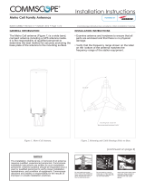
This instruction describes how to unpack and adjust a factory assembled VHLP(X)3
antenna.
Mount to the left of the supporting structure. It can also be configured to mount to right -
refer to full antenna assembly instructions on CommScope.com
INTRODUCTION
Page 3 of 14
7835437
CONTENTS & INTRODUCTION
SECTION 1
INSTALLATION
INSTRUCTIONS

Page 4 of 14
7835437
SAFETY INSTRUCTIONS
SECTION 2
INSTALLATION
INSTRUCTIONS

Page 5 of 14
7835437
SAFETY INSTRUCTIONS
SECTION 2
INSTALLATION
INSTRUCTIONS

Page 6 of 14
7835437
SAFETY INSTRUCTIONS
SECTION 2
INSTALLATION
INSTRUCTIONS

Table 1 Supplied Equipment
Page 7 of 14
7835437
EQUIPMENT AND TOOLS
SECTION 3
INSTALLATION
INSTRUCTIONS
TOOL REQUIREMENTS
Tools
*Either Item B (Integration Unit) or Item C (Flange Hardware Kit) are supplied.
Item
Qty
Description
A
1
Assembled antenna
B
1
Integration Unit *
C
1 or 2
Flange Hardware Kit *
Tools Required
Thread Diameter in MM
M4 M8 M10
Ring and Open Spanner (A/F)
17mm
Torque Wrench
2.5 - 95Nm
Sockets (A/F)
17mm
Allen Key (A/F)
3mm 6mm 8mm

OEM direct mount radio integration (certain models
only). Non-integrated antennas have factory feed fitted
flange outputs.
Handle antenna
CAREFULLY at
all times
A
B
Non-integrated antennas
supplied flange hardware kit this
will vary dependent on antenna
model
C
Page 8 of 14
7835437
UNPACKING
SECTION 4
INSTALLATION
INSTRUCTIONS
Unpacking

Carefully lay antenna on clear, flat ground.
Then remove brace
Do not apply excessive weight to antenna assembly.
Do not discard
these parts
Non-integrated antennas have factory feed fitted flange outputs
this will vary dependent on antenna model
Page 9 of 14
7835437
UNPACKING
SECTION 4
INSTALLATION
INSTRUCTIONS

galv
38Nm
5%
90-120mm Pole
Secure assembled mount to pole ensuring
clamp bolts are seated correctly.
This mount can only be used
for pole diameters from 90-120 mm
Pole to be structural engineer
approved rigid structural support
SLING
2
Elevation
adjustment nut
1
Loosen ½ turn,
do not remove.
1
Loosen ½ turn,
do not remove.
1
Loosen ½ turn,
do not remove.
Elevation adjustment
Loosen 3 screws (1).
Adjust elevation by bolt head (2).
On completion tighten screws (1) to
38Nm ± 5%
Adjustment Range ±15°
Page 10 of 14
7835437
MOUNT ATTACHMENT AND ALIGNMENT
SECTION 5
INSTALLATION
INSTRUCTIONS
NEVER WALK
UNDER HOISTED
LOADS
Where required, fit radio integration unit at this stage - refer to instructions
supplied with integration unit.

Loosen screws G1
Loosen screws G2
Pan Left
Pan Right
Azimuth adjustment
Adjust eyebolt.
On completion tighten
screws
G1
to 50Nm ± 5% and
screw
G2
to 38Nm ± 5%
Adjustment Range ±15°
Torque to
38Nm
5%
Page 11 of 14
7835437
MOUNT ATTACHMENT AND ALIGNMENT
SECTION 5
INSTALLATION
INSTRUCTIONS

Antenna Offset Left
Antenna Offset Right
Refer to full antenna assembly instructions on www.commscope.com for details on
how to switch mount offset
Page 12 of 14
7835437
MOUNT ATTACHMENT AND ALIGNMENT
SECTION 5
INSTALLATION
INSTRUCTIONS

Remove blanking plate,
screws, washers
o-ring (gasket)
Step 1
Loose screws
1
2
a turn to allow
transition to rotate
transition
Step 2
Vertical polarisation
After fine adjustment, tighten
screws to a torque of
10Nm
5%
Flat provided to aid
fine polarisation
adjustment
Step 3
Horizontal polarisation
Remove blanking plate, screws, washers
o-ring (gasket) before using this polarisation.
Vertical polarisation
Horizontal polarisation
Remove blanking plate, screws washers
o-ring (gasket) before using this polarisation.
Feed port
TRANSITION POLARISATION ADJUSTMENT
INSTALLATION
INSTRUCTIONS
SECTION 6
7835437
Page 13 of 14
Single polarisation
Dual polarisation
For OEM direct mount radio integration installation of
integration unit see separated
INSTALLATION
INSTRUCTIONS
Prior to assembly of integration unit, remove any tape or
protective cap from feed port

Page 14 of 14
7835437
SECTION 7
INSTALLATION
INSTRUCTIONS
7 General Information
7.1 General maintenance
The antenna is designed such that minimal maintenance is required. Other
than strong wind conditions the unit is not subject to abnormal forces and
regular inspection and maintenance should ensure trouble free operation.
7.2 Cleaning of Antenna
If subsequent cleaning of the antenna is required solvent based solutions
must not be used.
GENERAL INFORMATION
/