Page is loading ...

ION
®
-E Series Low Power Carrier Access Point
Installation Guide • M0201AAC • April 2018

DISCLAIMER
ThisdocumenthasbeendevelopedbyCommScope,andisintendedfortheuseofitscustomersandcustomersupport
personnel.Theinformationinthisdocumentissubjecttochangewithoutnotice.Whileeveryefforthasbeenmadeto
eliminateerrors,CommScopedisclaimsliabilityforanydifficultiesarisingfromtheinterpretationoftheinformation
containedherein.Theinformationcontainedhereindoesnotclaimtocoveralldetailsorvariationsinequipment,norto
provideforeverypossibleincidenttobemetinconnectionwithinstallation,operation,ormaintenance.Thisdocument
describestheperformanceoftheproductunderthedefinedoperationalconditionsanddoesnotcovertheperformance
underadverseordisturbedconditions.Shouldfurtherinformationbedesired,orshouldparticularproblemsarisewhichare
notcoveredsufficientlyforthepurchaser'spurposes,contactCommScope.
CommScopereservestherighttochangeallhardwareandsoftwarecharacteristicswithoutnotice.
COPYRIGHT
©2018CommScope,Inc.AllRightsReserved.
Thisdocumentisprotectedbycopyright.Nopartofthisdocumentmaybereproduced,storedinaretrievalsystem,or
transmitted,inanyformorbyanymeans,electronic,mechanicalphotocopying,recording,orotherwisewithouttheprior
writtenpermissionofCommScope.
Forpatentsseewww.cs-pat.com.
TRADEMARKS
Alltrademarksidentifiedby®or™areregisteredtrademarksortrademarks,respectively,ofCommScope,Inc.Namesof
otherproductsmentionedhereinareusedforidentificationpurposesonlyandmaybetrademarksand/orregistered
trademarksoftheirrespectivecompanies.
AndrewWirelessSystemsGmbH,19-December-2017

M0201AAC ION®-E Series Low Power Carrier Access Point Installation Guide
© April 2018 CommScope, Inc. Page iii
TABLE OF CONTENTS
Document Overview .................................................................................................................................................................................. 1
Document Revision History ..............................................................................................................................................................................1
Document Cautions and Notes......................................................................................................................................................................... 2
Abbreviations Used in this Guide .....................................................................................................................................................................2
CommScope Part Numbers .............................................................................................................................................................................. 2
ION-E Series System Overview................................................................................................................................................................... 3
CAP L Overview ......................................................................................................................................................................................... 4
CAP L Connectors, Ports, and LEDs................................................................................................................................................................... 5
CAP L with an Optical Fiber Interface.........................................................................................................................................................6
CAP L with a Copper Interface and External DC Power..............................................................................................................................7
CAP L with a Copper Interface and Power Cat6A Cable.............................................................................................................................8
Fan Interface Port.......................................................................................................................................................................................9
CAP L Accessory Options ..................................................................................................................................................................................9
Fan Kit.......................................................................................................................................................................................................10
Flat Mounting Bracket Kit......................................................................................................................................................................... 10
CAP L Mounting Bracket Kit .....................................................................................................................................................................10
CAP L Hybrid Fiber Splice Box Kit..............................................................................................................................................................11
AC/DC Power Supply Kit........................................................................................................................................................................... 11
OCTIS Kits .................................................................................................................................................................................................11
Safely Working with ION-E Hardware ...................................................................................................................................................... 12
Health and Safety Precautions .................................................................................................................................................................12
Property Damage Warnings ..................................................................................................................................................................... 12
General Installation Safety Requirements ............................................................................................................................................... 12
Guard Against Damage from Electro-Static Discharge.............................................................................................................................13
Compliance............................................................................................................................................................................................... 13
Equipment Symbols Used / Compliance ..................................................................................................................................................15
Installing CAP Ls....................................................................................................................................................................................... 16
Prepare for Installation................................................................................................................................................................................... 16
Required Distances Between CAP Ls and Antennas ....................................................................................................................................... 16
CAP L Installation Rules .................................................................................................................................................................................. 16
Cascade Rules .................................................................................................................................................................................................17
Recommended Tools and Material ..........................................................................................................................................................18
Determine the Power Consumption of the CAP L....................................................................................................................................18
Determine the CAP L Mounting Site ........................................................................................................................................................19
General Mounting Cautions .....................................................................................................................................................................21
Unpack and Inspect the CAP L and Optional Accessories ........................................................................................................................22
Mount the CAP L.............................................................................................................................................................................................22
Flat-Surface Mount a CAP L......................................................................................................................................................................23
Wall Mount a CAP L..................................................................................................................................................................................24
Mounting Orientation for Wall Mounts.............................................................................................................................................24
Wall Mount a CAP L Using a Flat Mounting Bracket Kit.....................................................................................................................26
Wall Mount a CAP L Using a CAP L Hybrid Fiber Splice Box Kit.......................................................................................................... 28
Wall Mount a CAP L Using a AC/DC Power Supply Kit .......................................................................................................................32
Ceiling Mount a CAP L ..............................................................................................................................................................................35
Ceiling Mount a CAP L without a Fan Kit............................................................................................................................................35
Ceiling Mount a CAP L with a Fan Kit .................................................................................................................................................35
(Optional) Ground the CAP L ..........................................................................................................................................................................36
Connect the CAP L Cables...............................................................................................................................................................................37
Cable a CAP L with an Optical Fiber Interface .......................................................................................................................................... 37
Cable a CAP L with a Copper Interface.....................................................................................................................................................40
Cat6A Cable Requirements for CAP Ls with a Copper Interface ........................................................................................................ 40
Cable a CAP L with a Copper Interface and External DC Power.........................................................................................................43
Cable a CAP L with a Copper Interface and Power over Cat6A Cable................................................................................................45
Powering a CAP L ............................................................................................................................................................................................ 48
Power LED Behavior ................................................................................................................................................................................. 48
Using the Power-Down Button ................................................................................................................................................................48
CAP L Maintenance.................................................................................................................................................................................. 49
Remove a CAP L from a Wall or Ceiling Mount ..............................................................................................................................................49
Preventative CAP L Maintenance for CAP Ls with the Fan Kit Option............................................................................................................49
Cat6A Specifications and Testing Requirements....................................................................................................................................... 50

ION®-E Series Low Power Carrier Access Point Installation Guide M0201AAC
Page iv © April 2018 CommScope, Inc.
Table of Contents
Contacting CommScope ........................................................................................................................................................................... 51
DCCS Global Technical Support ...................................................................................................................................................................... 51
Telephone Helplines.................................................................................................................................................................................51
Online Support ......................................................................................................................................................................................... 51
Waste Electrical and Electronic Equipment Recycling....................................................................................................................................51
Hardware to Software Mapping Information.................................................................................................................................................52
DCCS Technical Training ................................................................................................................................................................................. 52
Accessing ION-E Series User Documentation .................................................................................................................................................53

M0201AAC ION®-E Series Low Power Carrier Access Point Installation Guide
© April 2018 CommScope, Inc. Page 1
DOCUMENT OVERVIEW
ThisinstallationguideprovidesaproductoverviewandinstallationinstructionsfortheION-ESeriesLow
PowerCarrierAccessPoint(CAP
L),whichallowstransmissionbetweenION-Eequipment,antennas,and
Ethernetdevices(suchasWiFiandIPcameras).
Table1liststheCAPLmodelsthatthisinstallationguidesupports.
Document Revision History
ThisisthethirdreleaseoftheION
®
-ESeriesLowPowerCarrierAccessPointInstallationGuide,CommScope
DocumentNumberM0201AAC,datedJanuary2018,which
• adds
– supportfortheCAPL17E/19/23/25TDD
– "RequiredDistancesBetweenCAPLsandAntennas”onpage16
• updates
– therequiredclearancebetweenaCAPLandanantennain"GeneralInstallationSafetyRequirements”
onpage12
– “AntennaStmtforISED:”and“AntenneStmtpourISDE:”onpage14.
Table 1. Supported CAP L Models
Part Number
1
Model Name
7770203-000x CAP L 17E/17E/23/23
7770209-000x CAP L 18/21/26/26
7770356-000x CAP L 17E/17E/19/19
7776596-000x CAP L 7/80-85/17E/19
7776597-000x CAP L 17E/19/23/25TDD
1 The “-000x” suffix provides information as to whether the CAP L has a Fiber or
Copper interface, and the power and Fan Kit options. Contact your local sales
representative for further information.
For further information on ION-E system components, refer to the ION-E Series WCS-2, WCS-4, and e-POI
Subracks and Power Supply Unit Installation Guide and the ION-E Series Universal Access Point Installation
Guide (see "Accessing ION-E Series User Documentation” on page 53.)
For information on how to find the minimum software requirements for ION-E hardware, refer to
"Hardware to Software Mapping Information” on page 52.

ION®-E Series Low Power Carrier Access Point Installation Guide M0201AAC
Page 2 © April 2018 CommScope, Inc.
Document Overview
Document Cautions and Notes
Thisdocumentcontainsnotes,cautions,andwarnings.Ingeneral,cautions,warnings,andnotesindicatethe
following:
Abbreviations Used in this Guide
CommScope Part Numbers
TheCommScopeION-Epartnumbersinthisinstallationguideareintheformatofnnnnnnn-xx,wherethe
“-xx”suffixindicatesthelatestrelease.ContactyourlocalCommScopesalesrepresentativeforthecurrent
releasepartnumber.
The icon to the left is used to indicate a caution or warning. Cautions and warnings indicate operations or
steps that could cause personal injury, induce a safety problem in a managed device, destroy or corrupt
information, or interrupt or stop services.
The icon to the left indicates a caution or warning that pertains to laser equipment.
The icon to the left is indicates a caution or warning that pertains to Radio Frequency (RF).
The icon to the left indicates that the hardware is susceptible to Electro-Static Discharge (ESD) damage.
The icon to the left is indicates a Note. Notes provide information about special circumstances.
AUX Auxiliary ISDE Innovation, Sciences et Développement économique Canada
C Celsius ISED Innovation, Science and Economic Development Canada
CAN Central Area Node kg Kilogram
CAP L Carrier Access Point, Low Power LED Light Emitting Diode
Cat Category MHz Megahertz
CAT Copper Transport mm Millimeter
dB Decibel MMF Multi-Mode Fiber
dBm Decibel-milliwatts OPT Optical Transport
DC Direct Current PN Part Number
DCCS Distributed Coverage and Capacity Solutions RAN Regional-Area Network
EFTA European Free Trade Association RF Radio Frequency
EMC Electromagnetic Compatibility RU Rack Unit
EME
A
Europe, Middle East, Africa SFP Small Form-Factor Pluggable
EU European Union SMF Single-Mode Fiber
F Fahrenheit TEN Transport Expansion Node
FCC Federal Communications Commission UAP Universal Access Point
Gb Gigabyte Vdc Volts, direct current
GHz Gigahertz W Watts

M0201AAC ION®-E Series Low Power Carrier Access Point Installation Guide
© April 2018 CommScope, Inc. Page 3
ION-E Series System Overview
ION-E SERIES SYSTEM OVERVIEW
ThissectiondescribestheION-Esystem,whichisaunifiedwirelessinfrastructureplatformdefinedaround
ITbasedarchitecture.Itbringstogetherlicensedwirelessandpower,plusGigabitEthernetforWiFiintoone
wirelesssystemthatcanscaletobuildingsizeandistechnologyandspectrumagnosticandadaptive.Abasic
ION-Esystemcomprisesthecomponentslistedbelow;seealso
Figure1.
• CentralAreaNode(CAN)—providesserver-levelcontrolandprimarysignaldistribution.WCS-2(2U)
andWCS-4(4U)Subrackoptionsareavailable.
• TransportExpansionNode(TEN)—connectstoaCANusingMulti-ModeorSingle-Modefiberasa
secondarydistributionpoint.WCS-2(2U)andWCS-4(4U)Subrackoptionsareavailable.
• AccessPoint—connectsaCANoraTENtoantennasorotherwirelessdevices.Onthedownlink,an
AccessPoint(AP)convertsdataarrivingattheAPtoanalogsignalsandsendsthemtoanantenna.Onthe
uplink,receivedsignalsaredigitizedandserializedintodatastreamswhicharesentbacktothe
CAN/TEN.EachAPcontainsuptofourtransceiverpathsforRFcoverage.APssupportsGigabitEthernet
forWiFi,IPcameras,orotherdevicesinadditiontowirelessoveracommoncable.AnAPcanbeanyof
thefollowing:
– UniversalAccessPoint(UAP)—connectstheCAN/TENtoaninternalantenna;receivesdataand
powerthroughCat6Atwistedpaircabling.
– UAP-X—similarinfunctionasthestandardUAP,inadditiontoCommercialfrequencies,theUAP-X
alsosupportsPublicSafetyfrequencies,including700,800and400MHz.TheUAP-Xconnectsthe
CAN/TENtoexternalantennasandsupportsanextensivefrequencyrange.
– UAP-N25andUAP-XN25—similarinfunctionastheUAPandUAP-X,theUAP-N25andUAP-XN25
featurea25
MHzfilterononepath(insteadofthe80MHzfilteronaUAPorUAP-X).Thisallows
coexistenceofspecificbands,suchasAustralia850
MHzand900MHz.
– LowPowerCarrierAccessPoint(CAPL)—interfaceswiththeCAN/TENviaaCat6Acableoran
opticallink.ThisallowstheCAP
LtoprovidedataoverCopper,Single-ModeFiber(SMF),or
Multi-ModeFiber(MMF).PowerforCAP
LswithaCopperInterfacecanbeprovidedoverCat6Aor
ExternalAC/DC.PowerforCAP
LswithaFiberInterfaceisprovidedoverExternalAC/DCorremotely
throughhybridfiber.
Figure 1. Basic ION-E System
A WCS-2 and a WCS-4 can be configured for use as a CAN or a TEN. When the information in this guide
applies to both configurations, the term “CAN/TEN” is used. When the information pertains to only one
of the configurations, that configuration will be identified singularly as “CAN” or “TEN.”
CAN TEN WiFi IP CameraAccess Point MM/SM FiberCat6A

ION®-E Series Low Power Carrier Access Point Installation Guide M0201AAC
Page 4 © April 2018 CommScope, Inc.
CAP L Overview
CAP L OVERVIEW
TheLowPowerCarrierAccessPoint(CAPL)interfaceswiththeCAN/TENviaaCat6Acableoranopticallink.
ThisallowstheCAP
LtoprovidedataoverCopper,Single-ModeFiber(SMF),orMulti-ModeFiber(MMF).
PowerforCAP
LswithaCopperInterfacecanbeprovidedoverCat6AorexternalDC.PowerforCAPLswith
aFiberInterfaceisprovidedoverExternalAC/DCorremotelythroughhybridfiber.
Onthedownlink,theCAPLconvertsdataarrivingattheCAPLtoanalogsignalsandsendsthemtothe
Antennaports.Ontheuplink,receivedsignalsaredigitizedandserializedintodatastreams,whicharesent
backtotheCAN/TEN.EachCAP
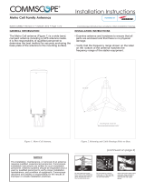
LcanprovideRFcoverageforuptofourspecificfrequencybands.Figure2
showshowaCAPLcanbedeployedinanION-Esystem.
Figure 2. CAP L in an ION-E System
TheCAPL
• operateswithinthefollowingtemperatureranges
– CAPLwithoutaFanKit(passivelycooled)
Opticalunits:-33°Cto+40°C(-27.4°Fto104°F)
Cat6Aunits:0°Cto+40°C(32°Fto104°F)
– CAPLwithaFanKit,themaximumoperatingtemperatureincreasesto55°C(131°F);seealso"Fan
Kit”onpage10
• isoutdoorrated(IP67),however,theCat6Aunitsarenotdesignedforoutdooruse;see"Determinethe
CAPLMountingSite”onpage19
• hasatypicalpowerconsumptionof98W;seealso
– "FanKit”onpage10
– "DeterminethePowerConsumptionoftheCAPL”onpage18.
UAP
UAP
UAP
UAP
CAP L
CAP L
CAP L
CAP L
CAP L
CAP L
CAP L
CAP L
CAP L
CAP L
Cat6A cable
Fiber
Power
TEN
TEN
Node B
e-POI
CAN
Remote
Powering

M0201AAC ION®-E Series Low Power Carrier Access Point Installation Guide
© April 2018 CommScope, Inc. Page 5
CAP L Overview
CAP L Connectors, Ports, and LEDs
Thefollowingsectionsidentifytheconnectors,ports,andLEDsavailableonthedifferentCAPLmodels.
• "CAPLwithanOpticalFiberInterface”onpage6
• "CAPLwithaCopperInterfaceandExternalDCPower”onpage7
• "CAPLwithaCopperInterfaceandPowerCat6ACable”onpage8
• "PoweringaCAPL”onpage48
• "FanInterfacePort”onpage9.

ION®-E Series Low Power Carrier Access Point Installation Guide M0201AAC
Page 6 © April 2018 CommScope, Inc.
CAP L Overview
CAP L with an Optical Fiber Interface
REF # Label Description Function
1, 4 ANT 3, ANT 4 Not available; connector is plugged.
2 ANT 1 4.3-10 RF connector Connect to two separate external antennas or to two ports on a cross-polarized dual antenna
via 50Ω coaxial cable. Each connector supports two RF bands. The end of the 50Ω coaxial cable
that connects to an ANT connector can be either a push-pull or a threaded connector. ANT 1/2
ship with dust caps that can be discarded upon unit installation.
3ANT 2
5Power LED
(Unlabeled)
Power LED
See "Power LED Behavior” on page 48.
6 Unlabeled Proprietary 4-pin 36
to 60 Vdc Power
connector
Connects to a local or remote DC power supply, or to a Hybrid Fiber Junction Box.
7 2 Optical Port 2 Connects to an optional cascaded CAP L via an Optical OCTIS Kit (PN 7770612). Port 2 provides
the main signal interface. Optical transport occurs over Single Mode Fiber (SMF) or Multi Mode
Fiber (MMF). Port 2 ships with factory-installed EMI/weatherproof plug, and must remain
plugged if not in use. Graphic shows the OCTIS connector in blue.
8 1 Optical Port 1 Connects to an ION-E CAN/TEN (possibly through a local Hybrid Fiber Junction Box) and
provides the main signal interface. Optical transport occurs over Single Mode Fiber (SMF) or
Multi Mode Fiber (MMF). Uses the Optical OCTIS Kit (PN 7770612). Port 1 ships with a dust cap
that can be discarded upon unit installation. Graphic shows the OCTIS connector in blue.
9 A RJ45 Auxiliary port Connects to external Ethernet devices such as WiFi and IP cameras. Cabling is via the
appropriate CAT cable for the protocol; this model supports a 1000 BASE-T and 802.3at Class 4
Power over Cat6A Ethernet connection. Maximum attached cable length is 3 meters (9.8 feet).
For information on the Auxiliary port in cascades, see "Cascade Rules” on page 17. Port A ships
with factory-installed EMI/weatherproof plug, and must remain plugged if not in use.
1
2
3
4
7
8
9
6
5

M0201AAC ION®-E Series Low Power Carrier Access Point Installation Guide
© April 2018 CommScope, Inc. Page 7
CAP L Overview
CAP L with a Copper Interface and External DC Power
REF # Label Description Function
1, 4 ANT 3, ANT 4 Not available; connector is plugged.
2ANT 1
4.3-10 RF connector
Connect to two separate external antennas or to two ports on a cross-polarized dual antenna
via 50Ω coaxial cable. Each connector supports two RF bands. The end of the 50Ω coaxial
cable that connects to an ANT connector can be either a push-pull or a threaded connector.
ANT 1/2 ship with dust caps that can be discarded upon unit installation.
3ANT 2
5Power LED
(Unlabeled)
Power LED
See "Power LED Behavior” on page 48.
6 Power button
(Unlabeled)
Pushbutton switch Places the CAP L into a low-power sleep state, which allows you to safely unplug the CAP L
without a power arc.
Prior to disconnecting the Power cable from the CAP L, press the Power button to power off
the CAP L.
7 Unlabeled Proprietary 4-pin 36
to 60 Vdc Power
connector
Connects to a local or remote DC power supply, or to a Hybrid Fiber Junction Box.
8 2 Port 2 Not applicable to this model configuration—do not remove the factory-installed
EMI/weatherproof plug.
9 1 Port 1 Port 1 connects to an available port on a CAT Card in the CAN/TEN via Cat6A cable and
provides the main signal interface. Uses the Ethernet OCTIS Kit (PN 7760652). Port 1 ships with
a dust cap that can be discarded upon unit installation.
10 A RJ45 Auxiliary port The Auxiliary port provides a cascade connection to an optional locally powered cascaded
CAP L, or provides a connection to external Ethernet devices such as WiFi and IP cameras.
Cabling is via the appropriate CAT cable for the protocol; this model supports a 1000 BASE-T
and 802.3at Class 4 Power over Cat6A Ethernet connection. Maximum attached cable length
is 100 meters (328 feet). Port A ships with factory-installed EMI/weatherproof plug, and must
remain plugged if not in use. For information on how to use the Auxiliary port in cascades, see
"Cascade Rules” on page 17.
1
2
3
4
7
8
9
10
5
6

ION®-E Series Low Power Carrier Access Point Installation Guide M0201AAC
Page 8 © April 2018 CommScope, Inc.
CAP L Overview
CAP L with a Copper Interface and Power Cat6A Cable
REF # Label Description Function
1, 4 ANT 3, ANT 4 Not available; connector is plugged.
2ANT 1
4.3-10 RF connector
Connect to two separate external antennas or to two ports on a cross-polarized dual
antenna via 50Ω coaxial cable. Each connector supports two RF bands. The end of the
50Ω coaxial cable that connects to an ANT connector can be either a push-pull or a
threaded connector. ANT 1/2 ship with dust caps that can be discarded upon unit
installation.
3ANT 2
5Power LED
(Unlabeled)
Power LED
See "Power LED Behavior” on page 48.
6Power
button
(Unlabeled)
Pushbutton switch Places the CAP L into a low-power sleep state, which allows you to safely unplug the
CAP L without a power arc. PowertoaCat6A CAP L mayalsobeshutdownviathe
ION-ESeriesSoftware.
Prior to disconnecting the Power cable from the CAP L, press the Power button to
power off the CAP L.
7 Unlabeled Proprietary 4-pin 36 to 60 Vdc
Power connector
Plugged, not applicable to this model configuration.
8 2 Port 2 Not applicable to this model configuration—do not remove the factory-installed
EMI/weatherproof plug.
9 1 Port 1 Port 1 connects to an available port on a CAT Card in the CAN/TEN via Cat6A cable and
provides the main signal interface and power over Cat6A. Uses the Ethernet OCTIS Kit
(PN 7760652). Port 1 ships with a dust cap that can be discarded upon unit installation.
10 A RJ45 Auxiliary port The Auxiliary port provides a cascade connection to an optional locally powered
Secondary CAP L, or provides a connection to external Ethernet devices such as WiFi
and IP cameras. Cabling is via the appropriate CAT cable for the protocol; this model
supports a 1000 BASE-T and 802.3at Class 4 Power over Cat6A Ethernet connection.
Maximum attached cable length is 100 meters (328 feet). Port A ships with
factory-installed EMI/weatherproof plug, and must remain plugged if not in use.
1
2
3
4
7
8
9
10
5
6

M0201AAC ION®-E Series Low Power Carrier Access Point Installation Guide
© April 2018 CommScope, Inc. Page 9
CAP L Overview
Fan Interface Port
Theprecedinggraphicshowstheproprietary8-pinFanInterfaceport,whichisonlyavailableonCAPLunits
thatshipwiththefactory-installedFanKit.IftheCAP
LbeinginstalledincludestheFanKitoption,theFan
InterfaceportwillbecabledtotheFanKitatthefactory.IftheCAP
LbeinginstalleddoesnotincludetheFan
Kitoption,theFanInterfaceportwillbeplugged.
CAP L Accessory Options
ThefollowingsectionsdescribehardwareoptionsfortheCAPL:
• "FanKit”onpage10
• "FlatMountingBracketKit”onpage10
• "CAPLMountingBracketKit”onpage10
• "CAPLHybridFiberSpliceBoxKit”onpage11
• "AC/DCPowerSupplyKit”onpage11
• "OCTISKits”onpage11.
Fan
Interface
port

ION®-E Series Low Power Carrier Access Point Installation Guide M0201AAC
Page 10 © April 2018 CommScope, Inc.
CAP L Overview
Fan Kit
TheoptionalFanKitisanintegratedshroudthatfitsovertheCAPLenclosuretoextendtheupperambient
temperaturerange.TheFanKit
• isIP55rated
• increasesthemaximumoperatingtemperatureto55°C(131°F)
• adds3WpowerconsumptiontotheCAPL;see"DeterminethePowerConsumptionoftheCAPL”on
page18.
• isfactoryinstalled,butcanbereplacedinthefield.
Flat Mounting Bracket Kit
TheFlatMountingBracketKit(CommScopePN7774353-xx)providesthemountingbracketsrequiredto
mountanCAP
Ltoawallorotherflatsurface.See"WallMountaCAPLUsingaFlatMountingBracketKit”on
page26.
CAP L Mounting Bracket Kit
TheCAPLMountingBracketKit(CommScopePN7774354-xx)providesthemountingbracketsrequiredto
mountanCAP
Ltoawallorotherflatsurfacewhenusingthe“CAPLHybridFiberSpliceBoxKit”orthe
“AC/DCPowerSupplyKit.”
Fan Kit

M0201AAC ION®-E Series Low Power Carrier Access Point Installation Guide
© April 2018 CommScope, Inc. Page 11
CAP L Overview
CAP L Hybrid Fiber Splice Box Kit
TheCAPLHybridFiberSpliceBoxKit(CommScopePN7781091-xx)separatesthepowerfromthefiber
signalsonahybridfiberfeedfromtheCAN/TEN.ItfeedspowertotheCAP
Lthroughacompositecablethat
includesbothfiberandcopperpowerwires.FiberandcopperterminateattheSpliceBox,whichallowsyou
toseparatetheDCwiresandfiberattheremoteend.ForCAP
LswithaFiberInterface,youwilltypicallyuse
compositecabletotransportsignalandpower,andthenusetheCAP
LHybridFiberSpliceBoxKitto
terminatethefiberattheCAP
L.See"WallMountaCAPLUsingaCAPLHybridFiberSpliceBoxKit”on
page28.
AC/DC Power Supply Kit
TheAC/DCPowerSupplyKit(CommScopePN7775087-xx)providesa48VExternalPowerSupplythat
convertslocalACpowertoDCpowerfortheCAP
L.WherevercopperisalreadyavailableforaCAPL
installation,aCAP
LwithCopperInterfaceshouldbeinstalled.However,inacascade,PoEisonlyavailable
forthePrimaryCAP
L—theSecondaryCAPLwillrequirelocalpowerandtheuseoftheAC/DCPowerSupply
Kit.Moreover,theAC/DCPowerSupplyKitcanbeusedforaFiberorCopperInterfacewhenremote
poweringisnotfeasible.See
"WallMountaCAPLUsingaAC/DCPowerSupplyKit”onpage32.
OCTIS Kits
AllCAPLsincludeoneOCTIS
1
KitfortheprimaryinterfacetotheCAN/TEN.RegardlessofwhichOCTISKit
shipswiththeCAPL,itwillplugintotheCAPLPort1.ItistheconfigurationoftheOCTISKitthatthenmakes
theAUXportcompatibleforaCopperInterfaceoraFiberInterface.
YoucanorderanadditionalOCTISKit,whichwouldallowyoutocascadetwoCAPLs,ortoattachanauxiliary
Ethernetdevice;whichOCTISKityoushouldorderisidentifiedin
Table2.
1 OCTISisatrademarkofRADIALL.
Table 2. CAP LOCTIS Kits
Kit Name CommScope PN Description
Optical OCTIS Kit 7770612 Use only with CAP Ls with a Fiber Interface to cascade a Secondary
fiber unit.
Ethernet OCTIS Kit 7760652 Use with CAP Ls that have a Fiber or Copper Interface to cascade a
Secondary copper unit, or to attach an auxiliary Ethernet device.

ION®-E Series Low Power Carrier Access Point Installation Guide M0201AAC
Page 12 © April 2018 CommScope, Inc.
Safely Working with ION-E Hardware
SAFELY WORKING WITH ION-E HARDWARE
Thefollowingsectionsprovideimportantinformationthatyoushouldreadandknowbeforeworkingwith
anyION-Ehardware.Observeallcautionsandwarningslistedinthissection.
Health and Safety Precautions
.
Property Damage Warnings
General Installation Safety Requirements
A high leakage current ground (earth) connection to the Power Supply Unit (PSU) is essential before
making any other connections to the PSU.
Laser radiation. Risk of eye injury in operation. Do not stare into the laser beam; do not view the laser
beam directly or with optical instruments.
High frequency radiation in operation. Risk of health hazards associated with radiation from the
antenna(s) connected to the unit. Implement prevention measures to avoid the possibility of close
proximity to the antenna(s) while in operation.
Keep operating instructions within easy reach and make them available to all users.
Only license holders for the respective frequency range are allowed to operate this unit.
Read and obey all the warning labels attached to the unit. Make sure that all warning labels are kept in a
legible condition. Replace any missing or damaged labels.
Make sure the unit's settings are correct for the intended use (refer to the manufacturer product
information) and regulatory requirements are met. Do not carry out any modifications or fit any spare
parts, which are not sold or recommended by the manufacturer.
Wet conditions increase the potential for receiving an electrical shock when installing or using electrically
powered equipment. To prevent electrical shock, never install or use electrical equipment in a wet
location or during a lightning storm.
This system is a RF Transmitter and continuously emits RF energy. Maintain a minimum 12-inch (30 cm)
clearance from the antenna while the system is operating. Whenever possible, shut down the RAN before
servicing the antenna.
Do not remove caps from any of the connectors until instructed to do so.
The CAP L is to be used only with CommScope (NEC Class 2) or Limited Power Source ION-E Subrack, or
equivalent.

M0201AAC ION®-E Series Low Power Carrier Access Point Installation Guide
© April 2018 CommScope, Inc. Page 13
Safely Working with ION-E Hardware
Guard Against Damage from Electro-Static Discharge
Compliance
1 Notice:Forinstallations,whichhavetocomplywithFCCRFexposurerequirements,theantenna
selectionandinstallationmustbecompletedinawaytoensurecompliancewiththoseFCCrequirements.
DependingontheRFfrequency,ratedoutputpower,antennagain,andthelossbetweentherepeaterand
antenna,theminimumdistanceDtobemaintainedbetweentheantennalocationandhumanbeingsis
calculatedaccordingtothisformula:
where
• P(mW)istheradiatedpowerattheantenna,i.e.themax.ratedrepeateroutputpowerinadditionto
theantennagainminusthelossbetweentherepeaterandtheantenna.
• PD(mW/cm²)istheallowedPowerDensitylimitacc.to47CFR1.1310(B)forgeneralpopulation/
uncontrolledexposureswhichis
– f(MHz)/1500forfrequenciesfrom300MHzto1500MHz
– 1forfrequenciesfrom1500MHzto100,000MHz
RFexposurecompliancemayneedtobeaddressedatthetimeoflicensing,asrequiredbytheresponsible
FCCBureau(s),includingantennaco-locationrequirementsof1.1307(b)(3).
2 Notice:ForinstallationswhichhavetocomplywithEuropeanEN50385exposurecompliance
requirements,thefollowingPowerDensitylimits/guidelines(mW/cm²)accordingtoICNIRParevalid:
• 0.2forfrequenciesfrom10MHzto400MHz
• F(MHz)/2000forfrequenciesfrom400MHzto2GHz
• 1forfrequenciesfrom2GHzto300GHz
3 Notice:Installationofthisequipmentisinfullresponsibilityoftheinstaller,whohasalsothe
responsibility,thatcablesandcouplersarecalculatedintothemaximumgainoftheantennas,sothatthis
value,whichisfiledintheFCCGrantandcanberequestedfromtheFCCdatabase,isnotexceeded.The
industrialboostersareshippedonlyasanakedboosterwithoutanyinstallationdevicesorantennasasit
needsforprofessionalinstallation.
4 Notice:ForinstallationswhichhavetocomplywithFCC/ISEDrequirements:
English:
ThisdevicecomplieswithFCCPart15.Operationissubjecttothefollowingtwoconditions:(1)this
devicemaynotcauseinterference,and(2)thisdevicemustacceptanyinterference,including
interferencethatmaycauseundesiredoperationofthedevice.
ThisdevicecomplieswithHealthCanada'sSafetyCode.TheinstallerofthisdeviceshouldensurethatRF
radiationisnotemittedinexcessoftheHealthCanada'srequirement.Informationcanbeobtainedat
http://www.hc-sc.gc.ca/ewh-semt/pubs/radiation/radio_guide-lignes_direct-eng.php.
Electro-Static Discharge (ESD) can damage electronic components. To prevent ESD damage, always wear
an ESD wrist strap when working with ION-E hardware components. Not all ION-E hardware requires
grounding. For those ION-E hardware components for which grounding is required, connect the ground
wire on the ESD wrist strap to an earth ground source before touching the ION-E component. Wear the
wrist strap the entire time that you work with the ION-E hardware.
]/[
][
][
2
4
cmmW
mW
cm
PD
P
D
∗∗
=
π

ION®-E Series Low Power Carrier Access Point Installation Guide M0201AAC
Page 14 © April 2018 CommScope, Inc.
Safely Working with ION-E Hardware
Changesormodificationsnotexpresslyapprovedbythepartyresponsibleforcompliancecouldvoidthe
user'sauthoritytooperatetheequipment.
AntennaStmtforISED:
Thisdevicehasbeendesignatedtooperatewiththeantennashavingamaximumgainof9dBi.Antennas
havingagaingreaterthan9dBiareprohibitedforusewiththisdevicewithoutconsentbyISED
regulators.Therequiredantennaimpedanceis50ohms.
Theantenna(s)usedforthistransmittermustbeinstalledtoprovideaseparationdistanceofatleast30
cmfromallpersonsandmustnotbeco-locatedoroperatinginconjunctionwithanyotherantennaor
transmitter.Usersandinstallersmustbeprovidedwithantennainstallationinstructionsandtransmitter
operatingconditionsforsatisfyingRFexposurecompliance.
French:
CetappareilestconformeàFCCPartie15.SonutilisationestsoumiseàLesdeuxconditionssuivantes:(1)
cetappareilnepeutpasprovoquerd'interférenceset(2)cetappareildoitaccepterTouteinterférence,y
comprislesinterférencesquipeuventcauserunmauvaisfonctionnementdudispositif.
CetappareilestconformeavecSantéCanadaCodedesécurité6.Leprogrammed'installationdecet
appareildoits'assurerquelesrayonnementsRFn'estpasémisau-delàdeI'exigencedeSantéCanada.Les
informationspeuventêtreobtenues:
http://www.hc-sc.gc.ca/ewh-semt/pubs/radiation/radio_guide-lignes_direct-eng.php
Leschangementsoumodificationsnonexpressémentapprouvésparlapartieresponsabledela
conformitépourraientannulerl'autoritédel'utilisateuràutilisercetéquipement.
AntenneStmtpourISDE:
Cedispositifaétédésignépourfonctionneraveclesantennesayantungainmaximalde9dBi.Antennes
ayantungainplusgrandque9dBisontinterditespouruneutilisationaveccetappareilsansle
consentementdesorganismesderéglementationd'ISDE.L'impédanced'antennerequiseest50ohms.
L'antenne(s)utilisépourcetémetteurdoitêtreinstallépourfournirunedistancedeséparationd'au
moins30cmdetouteslespersonnesetnedoitpasêtreco-localiséesouopérantenconjonctionavecune
autreantenneouémetteur.Lesutilisateursetlesinstallateursdoiventêtrefournisavecdesinstructions
d'installationdel'antenneetdesconditionsdefonctionnementdel'émetteurpoursatisfairela
conformitéauxexpositionsRF.
5 Notice:TheunitcomplieswithOvervoltageCategoryII.Italsocomplieswiththesurgerequirement
accordingtoEN61000-4-5(fineprotection);however,installationofanadditionalmedium(vialocal
supplyconnection)and/orcoarseprotection(externalsurgeprotection)isrecommendeddependingon
theindividualapplicationinordertoavoiddamagecausedbyovercurrent.
ForCanadaandUS,componentsusedtoreducetheOvervoltageCategoryshallcomplywiththe
requirementsofIEC61643-series.Asanalternative,componentsusedtoreducetheOvervoltage
CategorymaycomplywithANSI/IEEEC62.11,CSACertificationNoticeNo.516,CSAC22.2No.1,orUL
1449.Suitabilityofthecomponentfortheapplicationshallbedeterminedfortheintendedinstallation.
6 Notice:Correspondinglocalparticularitiesandregulationsmustbeobserved.Fornationaldeviations,
pleaserefertotherespectivedocumentsincludedinthemanualCDthatisdeliveredwiththeunit.
7 Note:ForaClassBdigitaldeviceorperipheral:
ThisequipmenthasbeentestedandfoundtocomplywiththelimitsforaClassBdigitaldevice,pursuant
topart15oftheFCCRules.Theselimitsaredesignedtoprovidereasonableprotectionagainstharmful
interferenceinaresidentialinstallation.Thisequipmentgenerates,usesandcanradiateradiofrequency
energyand,ifnotinstalledandusedinaccordancewiththeinstructions,maycauseharmfulinterference
toradiocommunications.However,thereisnoguaranteethatinterferencewillnotoccurinaparticular
installation.Ifthisequipmentdoescauseharmfulinterferencetoradioortelevisionreception,whichcan

M0201AAC ION®-E Series Low Power Carrier Access Point Installation Guide
© April 2018 CommScope, Inc. Page 15
Safely Working with ION-E Hardware
bedeterminedbyturningtheequipmentoffandon,theuserisencouragedtotrytocorrectthe
interference.
8 Notice:ForaClassAdigitaldeviceorperipheral.
ThisequipmenthasbeentestedandfoundtocomplywiththelimitsforaClassAdigitaldevice,pursuant
toPart15oftheFCCRules.Theselimitsaredesignedtoprovidereasonableprotectionagainstharmful
interferencewhentheequipmentisoperatedinacommercialenvironment.Thisequipmentgenerates,
uses,andcanradiateradiofrequencyenergyand,ifnotinstalledandusedinaccordancewiththe
instructionmanual,maycauseharmfulinterferencetoradiocommunications.Operationofthis
equipmentinaresidentialareaislikelytocauseharmfulinterferenceinwhichcasetheuserwillbe
requiredtocorrecttheinterferenceathisownexpense.
9 Note:ThisunitcomplieswithEuropeanstandardEN60950-1/EN62368-1.
Equipment Symbols Used / Compliance
Pleaseobservethemeaningsofthefollowingsymbolsusedinourequipmentandthecompliancewarnings
listedin
Table3.
Table 3. Compliance Labels
Symbol Compliance Meaning
—FCC
For industrial (Part 20) signal booster:
WARNING: This is NOT a CONSUMER device. It is designed for installation by FCC LICENSEES and
QUALIFIED INSTALLERS. You MUST have an FCC LICENSE or express consent of an FCC Licensee to
operate this device. Unauthorized use may result in significant forfeiture penalties, including
penalties in excess of $100,000 for each continuing violation.
—ISED
WARNING: This is NOT a CONSUMER device. It is designed for installation by an installer approved
by an ISED licensee. You MUST have an ISED LICENCE or the express consent of an ISED licensee to
operate this device.
AVERTISSEMENT: Ce produit N'EST PAS un appareil de CONSOMMATION. Il est conçu pour être
installé par un installateur approuvé par un titulaire de licence d'ISDE. Pour utiliser cet appareil,
vous DEVEZ détenir une LICENCE d'ISDE ou avoir obtenu le consentement exprès d'un titulaire de
licence autorisé par ISDE.
CE
To be sold exclusively to mobile operators or authorized installers - no harmonized frequency
bands, operation requires license. Intended use: EU and EFTA countries.
Indicates conformity with the RED directive 2014/53/EU and/or RoHS directive 2011/65/EU.
CE
Indicates conformity with the RED directive 2014/53/EU and RoHS directive 2011/65/EU certified
by the notified body no. 0700.

ION®-E Series Low Power Carrier Access Point Installation Guide M0201AAC
Page 16 © April 2018 CommScope, Inc.
Installing CAP Ls
INSTALLING CAP LS
ThefollowingsectionsguideyouthroughtheinstallationofaCAPL.payattentiontoallcautions,andfollow
thestepsintheorderpresented.
Prepare for Installation
Dothefollowingbeforebeginninginstallation.
• Reviewandknowthecautionsin"SafelyWorkingwithION-EHardware”onpage12.
• Reviewthesystemdesignplan.
• Identifytheequipmentinstallationsite.
• Reviewthepowerrequirementstomakesurethesitecansupportthisinstallation.
• Mapoutallcableruns.
• Identifyandobtainalltoolsandmaterialsrequiredtocompletetheinstallation.
Required Distances Between CAP Ls and Antennas
Table4liststhedistancethatmustbemaintainedbetweenspecificCAPLmodelsandantennas.Seealsothe
requirementslistedin“AntennaStmtforISED:”and“AntenneStmtpourISDE:”onpage14.
CAP L Installation Rules
WheninstallingaCAPL,youmustobservethefollowingrules.
• CAPLwithaCopperInterface
– ConnectsviaitsRJ-45porttoaCATCardintheCAN/TEN
– EachCATPortcansupporttwoCopperCAPLs,butyoucannotexceedsixCAPLsperCATCard,for
maximumtotalsof24CAP
Lsinastraightcascadeconfiguration,and32CAPLsperWCSSubrackin
adaisy-chainconfiguration,butyoumustadheretotheCopperCAP
Lpoweringrules.
– Therecanbeatotalof12CAPLsconnectedtoaCATCardinacascadeconfiguration.TheCAPL
connectedtotheCATCardisthePrimaryCAP
L,towhichyoucanconnectoneself-powered
SecondaryCAP
L.See"CascadeRules”onpage17.
Table 4. Required Antenna Distance
CAP L Model
Antenna gain
without cable
loss [dBi]
Maximum Distance
FCC ISED
Meters Inches Meters Inches
CAP L 7/80 - 85 /17E / 19 9 .176 6.9 .256 10.1
CAP L 17E/17E/19/19 9 .218 8.58 .259 10.2
CAP L 17E/ 1 7E/23 / 2 3 9 .169 6.65 .237 9.33
CAP L 17E/ 1 9/23/ 2 5 TDD 9 .178 7.02 .251 9.88
/