Page is loading ...

Argus
®
Installation Instructions
296mm Profile Panel Antennas
Bulleti Bulletin D701-0013 • Revision C • November 2014 page 1 of 5
CommScope Infrastructure Academy offers installation training
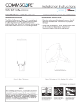
General
This instruction manual contains all necessary information required to assist in the correct
installation of ARGUS
Panel Antennas of 296mm (11.7”) width to a 75 – 115mm (3”-4.5”)
diameter pipe when using the mou
nting kit with clamp bracket. Th
ese antennas can be supplied
with either fixed
electrical beam downtilt (FET), manually adjustable electrical downtilt
(MET) or
AISG
-compatible remotely controlled electrical downtilt (RET). Mechanical downtilt is also
available if required, depending on the type of mounting kit selected.
Following symbols can be found next to text outlining important information.
Please follow the procedure marked with this symbol precisely.
Non
-compliance may lead to damage of the product.
Handy tips when instal
ling product.
Unpacking
Make sure that the antenna and the accessory items listed below are provided and have not been
damaged during transport.
· Antenna
· Mounting kit (mounting kit components for each configuration are shown in Figure
s 2
and 3).
· Hex key 6mm AF (supplied with adjustable downtilt antennas only).
Mounting Kit
Type
850mm – 1200mm
(33.5” – 43.3”) Antennas
1200mm – 1575mm
(43.3” – 62”) Antennas
1575mm – 2700mm
(62” – 106.3”) Antennas
Fixed Downtilt
F-042-GL-E
F-042-GL-E
F-042-GL-E
Mechanical
Downtilt
T-045-GL-E T-041-GL-E T-029-GL-E
Tilt range
0°, 2° -10° in 1° steps
0° - 12° in 1° steps
0° - 8° in 1° steps
Mounting
Bracket Spacing
Dim A (Fig 4)
716mm (28.2”) 976mm (38.4”) 1400mm (55.1”)
Table 1: Mounting Kit Part Numbers for Different Antennas
Do not install near power lines. Power lines,
telephone lines, and guy wires look the same.
Assume any wire or line can electrocute you.
Do not install on a wet or windy day or
when lightning or thunder is in the
area.
Do not use metal ladder.
Wear shoes with rubber soles and heels.
Wear protective clothing including a
long-sleeved shirt and rubber gloves.

296mm Profile Panel Antennas Bulletin D701-0013 • Revision C • November 2014 page 2 of 5
Installation Instructions
·
Ensure a torque spanner is used when tightening fasteners, see the mounting kit
diagrams on the following pages for the correct torque recommendations.
·
Ensure antenna is installed with the connectors at the bottom.
Installation Instructions – Adjustable Downtilt Mounting Kit
T-029-GL-E, T-041-GL-E, T-045-GL-E
Assemble
mounting kits as per Figure 2 and 3 of this document.
1. Attach the mounting kit assembly to the antenn
a, before trying to clamp the
brackets to the pole.
2. Downtilt angles in 1°
increments can be obtained with the correct adjustment
of the tilt arm bracket.
· D
owntilt can be achieved by aligning the corresponding hole in the tilt
arm to the pivot bracket whic
h mates against the mounting pole, as shown in
Figure 4. The first hole is for 1° downtilt*
, with each consecutive hole
resulting in an increased inclination of 1°.
( *Note for the T-045-GL-E kit the tilt is 0° then 2° - 10° in 1° steps.)
· For finer downtilt angle adjustments the distance in between the
top
and bottom mounting bracket on the pole can be adjusted.
· For 0° downtilt the tilt arm may be stowed as show in Figure 4.
· An inclinometer or
other angular measuring device may be used to
verify downtilt angle as required.
Upper Mounting Bracket Assembly
( To Suit Pipes OD 75-115 mm)
Lower Mounting Bracket Assembly
(To Suit Pipes OD 75-115 mm)
Figure 1: Correctly Assembled Mounting Kit Using Clamp Bracket for Mechanically
Adjustable Downtilt Antenna

Bulletin D701-0013 • Revision C • November 2014 page 3 of 5 296mm Profile Panel Antennas
Figure 2: Exploded Assembly for Upper Mounting Bracket using Clamp Bracket
Figure 3: Exploded Assembly for Lower Mounting Bracket using Clamp Bracket
(This configuration should also be used for the upper Mounting Bracket when 0° tilt is
required)
Figure 4: Typical Example of Upper Bracket Placement for Various Downtilts
OPTIONAL: THE TILT ARM AND EXTRA HARDWARE
CAN
BE STOWED IN THE POSITION SHOWN WHEN
IN
0° DOWNTILT
CONFIGURATION
USING A CLAMP
BRACKET.
A

296mm Profile Panel Antennas Bulletin D701-0013 • Revision C • November 2014 page 4 of 5
Operation of Antennas
F
ET Antennas
The beam downtilt is factory set.
MET
Antennas
The beam downtilt below the horizon is adjusted by rotating the hex socket
located at the bottom of the antenna
- Figure 5
). Turning the hex socket in
a clockwise direction increases the beam downtilt below the horizon.
Turning the hex socket in an anti
-
clockwise direction decreases the beam
downtilt below the horizon. Be
am downtilt setting
in degrees below
boresight
can be read off the scale at the base of the antenna.
The downtilt
setting is read from th
e face of the antenna bottom end cap
at the point
where the scale protrudes.
AISG Compliant
RET
Antennas
AISG Complian
t antennas are compatible with AISG co
mpliant control
unit equipment. For operation of downtilt using AISG compliant controllers
see the controller documentation.
Where manual override of RET control is
provided at the antenna bottom end cap, operation is identical to that
described above for MET antennas.
WARNING:
During downtilt adjustment ensure the hex socket is not
tu
rned past the minimum and maximum positions
as shown on the downtilt
indicator scale. Forcing the hex adjustment beyond this point
may lead to
damage of the downtilt mechanism. Using power drills and electric
screwdrivers to adjust downtilt may also lead to damage of the
downtilt mechanism.
Port and Band
Identification
Each RF and/or AISG port on the antenna is numbered and identified in
accordance with AISG Standard “AIS
G Antenna Port Color Coding”.
Each
pair of ±45° polarized RF ports on the antenna (an array) is
commonly termed a “Band”. Using this terminology,
the band
ID numbers
rise
in step with the port numbers, ie Ba
nd 1 corresponds with Ports 1 & 2,
Band 2 corresponds with Ports 3 & 4 etc.
Ports are numbered starting with RF low frequency band(s) first, followed
by higher frequency band
(s)
. For bands operating at the same RF frequency,
ports associated with arrays at the bottom of the antenna are numbered
before ports associated with arrays at the top.
For remote tilt
antennas, depending on the configuration
of AISG employed
(Single RET or Multi RET)
,
the antenna will report the bands differently to
the primary controller as follows:
SRET
: For either AISG1.1 or 2.0, a multiband antenna configured as
cascaded SRET
will
report to the primary controller as multiple antennas,
each with a single band. Each band of the antenna will report a different
serial number. For example, a tri band antenna with serial number
60051007 will report to the controller three individual antennas with serial
numbers 600510071, 600510072, 600510073, where the last digit
represents the band of the antenna.
MRET: When using AISG2.0, a multiband antenna will report to the
primary controller as a single antenna with multiple bands. Each band of
the antenna is accessible through the controller.

Bulletin D701-0013 • Revision C • November 2014 page 5 of 5 296mm Profile Panel Antennas
End Cap Layout for Typical Antennas
Figure
6:
Typical
6
-port (RVVPX
)
with internal bias
tee on Port 1.
Note: The phase of
Band
2 (ports 3 and
4)
and
Band 3 (ports 5
and
6
) are
situated above
that of
Band 1
(ports 1
and
2).
Tilt adjust and scale
(Band 1)
Tilt adjust and scale
(Band 3)
Tilt adjust and scale
(Band 2)
CommScope
1100 CommScope Place
SE P.O. Box 339, Hickory, NC 28603-
0339
(828) 324
-2200 (800) 982-1708
www.commscope.com/andrew
Customer Service 24 hours
North America: +1
-800-255-1479 (toll free)
Any country: +1
-779-435-6500
email: acicustomersupportcen[email protected]
Notice: CommScope disclaims any liability or responsibility for the results of improper or unsafe installation, inspection, maintenance, or removal practices.
Aviso: CommScope no acepta ninguna obligación ni responsabilidad como resultado de prácticas incorrectas o peligrosas de instalación, inspección, mantenimiento o retiro.
Avis : CommScope décline toute responsabilité pour les conséquences de procédures d’installation, d’inspection, d’entretien ou de retrait incorrectes ou dangereuses.
Hinweis: CommScope lehnt jede Haftung oder Verantwortung für Schäden ab, die aufgrund unsachgemäßer Installation, Überprüfung, Wartung oder Demontage auftreten.
Atenção: A CommScope abdica do direito de toda responsabilidade pelos resultados de práticas inadequadas e sem segurança de i
nstalação, inspeção, manutenção ou remoção.
Avvertenza: CommScope declina eventuali responsabilità derivanti dell’esecuzione di procedure di installazione, ispezione, manutenzione e smontaggio improprie o poco sicure.
⌘˖CommScope ޜਨ⭣᰾ሽᯬнᚠ⮦ᡆнᆹޘⲴᆹ㼍ǃ⃒傇ǃ㏝؞ᡆনᡰሾ㠤Ⲵਾ᷌н䋐ԫօ㗙उ઼䋜ԫ
© 2014 CommScope Bulletin D701-0013
/