Page is loading ...

CommScope Era
™
Fiber Low Power Carrier Access Point
Installation Guide • M0201ANC_uc • June 2019

DISCLAIMER
This document has been developed by CommScope, and is intended for the use of its customers and customer support
personnel. The information in this document is subject to change without notice. While every effort has been made to
eliminate errors, CommScope disclaims liability for any difficulties arising from the interpretation of the information
contained herein. The information contained herein does not claim to cover all details or variations in equipment, nor to
provide for every possible incident to be met in connection with installation, operation, or maintenance. This document
describes the performance of the product under the defined operational conditions and does not cover the performance
under adverse or disturbed conditions. Should further information be desired, or should particular problems arise which are
not covered sufficiently for the purchaser's purposes, contact CommScope.
CommScope reserves the right to change all hardware and software c
haracteristics without notice.
COPYRIGHT
© 2019 CommScope, Inc. All Rights Reserved.
This document is protected by copyri
ght. No part of this document may be reproduced, stored in a retrieval system, or
transmitted, in any form or by any means, electronic, mechanical photocopying, recording, or otherwise without the prior
written permission of CommScope.
For patents see www.cs-pat.com.
TRADEMARKS
All trademarks identified by ® or ™ are registered trademarks or trademarks, respectively, of CommScope, Inc. Names of
other products mentioned herein are used for identification purposes only and may be trademarks and/or registered
trademarks of their respective companies.
Andrew Wireless Systems GmbH, 17-June-2019

M0201ANC_uc CommScope Era
™
Fiber Low Power Carrier Access Point Installation Guide
© June 2019 CommScope, Inc. Page iii
TABLE OF CONTENTS
Document Overview .................................................................................................................................................................................. 1
Document Revision History ..............................................................................................................................................................................1
Document Cautions and Notes......................................
...................................................................................................................................2
Abbreviations Used in this Guide .....................................................................................................................................................................3
CommScope Part Numbers ..............................................................................................................................................................................3
Era System Overview .................................................................................................................................................................................
4
Fiber CAP L Overview.................................................................................................................................................................................
5
Connectors and LED for the Fiber CAP L...........................................................................................................................................................6
CAP L Accessories and Options..........................................
............................................................................................................................... 7
Fan Kit.........................................................................................................................................................................................................7
Mounting and Power Kits........................................................................................................................................................................... 8
OCTIS Kits ........................................................
...........................................................................................................................................9
SFP+ Modules............................................................................................................................................................................................. 9
Plan and Prepare for a Fiber CAP L Installation.........................................................................................................................................
10
Maximum Number of Fiber CAP Ls Supported in an Era System ......................................
.............................................................................10
Cascade Rules for Fiber CAP Ls.......................................................................................................................................................................11
Cat6A Cable Requirements for Ethernet Devices ........................................................................................................................................... 12
Safely Working with Era Hardware................................
.................................................................................................................................12
Health and Safety Precautions .................................................................................................................................................................12
Property Damage Warnings ..................................................................................................................................................................... 13
General Installation Safety Requirements ..........................
.....................................................................................................................13
Guard Against Damage from Electro-Static Discharge.............................................................................................................................13
Compliance............................................................................................................................................................................................... 14
Equipment Symbols Used / Compliance .............................
.....................................................................................................................16
Required Antenna Distances....................................................................................................................................................................16
Determine the Power Consumption of the CAP L ..........................................................................................................................................17
Determine the CAP L Installation Site................................................
.............................................................................................................17
CAP L Dimensions.....................................................................................................................................................................................18
Mounting Dimensions for a CAP L with the Flat Mounting Bracket Kit ............................................................................................. 18
Mounting Dimensions for Two CAP Ls Mounted with the Dual Mounting Kit .............................
.....................................................19
Mounting Dimensions for a CAP L Mounted with the CAP L Hybrid Fiber Splice Box Kit ..................................................................20
Mounting Dimensions for a CAP L Mounted with the AC/DC Power Supply Kit................................................................................21
CAP L Weights .........................................................
.................................................................................................................................21
Extended CAP L Temperature Operation .................................................................................................................................................22
Recommended Tools and Material ................................................................................................................................................................23
Unpack and Inspect the CAP L and Optional Accessories......................................
......................................................................................... 23
Obtain the Required Materials....................................................................................................................................................................... 23
Mount the Fiber CAP L .............................................................................................................................................................................
24
General Mounting Cautions.......................................
.....................................................................................................................................24
Mounting a CAP L with a Flat Mounting Bracket Kit..............................
.........................................................................................................25
Attach the Flat Mounting Bracket Kit to the CAP L .................................................................
................................................................. 26
Flat-Surface Mount a CAP L.................................................................
.....................................................................................................27
Wall Mount a CAP L..................................................................................................................................................................................29
Mounting Orientation for Wall Mounts............................
.................................................................................................................29
Wall Mount a CAP L Using a Flat Mounting Bracket Kit.....................................................................................................................30
Mounting Two CAP Ls with a Dual Mounting Kit............................................................................................................................................31
Mounting a CAP L with an AC/DC Power Supply Kit..................................
.....................................................................................................38
Wiring the AC/DC Power Supply Kit. .............................................................................................................................................................. 38
Mounting a CAP L with a Hybrid Fiber Splice Box Kit .....................................................................................................................................43
Prepare for CAP L Hybrid Fiber Splice Box Kit Installation ......................
.................................................................................................43
Assembling and Wiring the Hybrid Fiber Splice Box ................................................................................................................................43
Wire the Hybrid Fiber Splice Box .......................................................................................................................................................44
Wire a Hybrid Fiber Splice Box for 4-Wi
re Power with Limited Power Source.................................................................................. 47
Wire a Hybrid Fiber Splice Box for 2-Wire Power without Limited Power Source ............................................................................49
Wire a Hybrid Fiber Splice Box to Cascade Two CAP Ls with the 2-Wire Power Configuration.........................................................50
Wire a Hybrid Fiber Splice Box to Cascade Two CAP Ls with the 4-Wire Power Configuration...........................
..............................51
Wall Mount a CAP L Using a CAP L Hybrid Fiber Splice Box Kit ................................................................................................................52
Ceiling Mount a CAP L.....................................................................................................................................................................................54
Ceiling Mount a CAP L without a Fan Kit.............................................
.....................................................................................................54
Ceiling Mount a CAP L with a Fan Kit .......................................................................................................................................................54

CommScope Era
™
Fiber Low Power Carrier Access Point Installation Guide M0201ANC_uc
Page iv © June 2019 CommScope, Inc.
Table of Contents
Connect the Cables to the Fiber CAP L...................................................................................................................................................... 55
Ground the Fiber CAP L (Optional) .................................................................................................................................................................55
Connect the Fiber CAP L to a Passive RF Antenna ..........................................................................................................................................56
Clean the RF Cable Connectors ...................................
............................................................................................................................. 57
Connect the Passive RF Antenna..............................................................................................................................................................59
Connect the Fiber CAP L to a Classic CAN or TEN ...........................................................................................................................................60
Cascade a Secondary Fiber CAP L (Optional).....................................................
.............................................................................................61
Connect an External Ethernet Device (Optional)............................................................................................................................................62
Connect to Vdc Power ....................................................................................................................................................................................62
Powering on a Fiber CAP L .......................................................................................................................................................................
62
CAP L Maintenance..................................................................................................................................................................................
63
Remove a CAP L from a Wall or Ceiling Mount ..............................................................................................................................................63
Preventative CAP L Maintenance for CAP Ls with the Fan Kit Option.......................................
..................................................................... 63
Contacting CommScope ...........................................................................................................................................................................
64
CMS Global Technical Support ....................................................................................................................................................................... 64
Telephone Helplines................................................
.................................................................................................................................64
Online Support ......................................................................................................................................................................................... 64
Waste Electrical and Electronic Equipment Recycling....................................................................................................................................64
Hardware to Software Mapping Information........................
.........................................................................................................................65
Mobility Solutions Technical Training............................................................................................................................................................. 65
Accessing Era/ION-E Series User Documentation .......................................................................................................................................... 66

M0201ANC_uc CommScope Era
™
Fiber Low Power Carrier Access Point Installation Guide
© June 2019 CommScope, Inc. Page 1
DOCUMENT OVERVIEW
There are two variants available for Low Power Carrier Access Points (CAP L): one variant has an optical fiber
interface (Fiber CAP L), and the other has a copper interface (Copper CAP L). This installation guide provides
a product overview and installation instructions fo
r the Fiber CAP L. (For information on the Copper CAP L,
refer to
the CommScopeEra™CopperLowPowerCarrierAccessPointInstallationGuide; see "A c c e ss i n g
Era/ION-E Series User Documentation” on
page 66). Table 1 lists the CAP L models that this installation guide
supports.
Table 1. Supported CAP L Models
Part Number
1
Model Name
7770203-000x CAP L 17E/17E/23/23
7770209-000x CAP L 18/21/26/26
7770356-000x CAP L 17E/17E/19/19
7776595-000x CAP L 9/18/18/21
7776596-000x CAP L 7/80-85/17E/19
7776597-000x CAP L 17E/19/23/25TDD
7776598-000x CAP L 9/18/21/26
7776641-000x CAP L 8/9/18/21
7776643-000x CAP L 8/18/21/26
1 The “-000x” suffix provides information as to
wh
eth
er the CA P L has a Fiber or Copper
interface, and the power and Fan Kit options.
Contact your local sales representative for
further information.
For information on how to find the minimum software requirements for Era hardware, refer to "Hardware
to Software Mapping Information” on page 65.
Document Revision History
This is the third release of the CommScopeEra™FiberLowPowerCarrierAccessPointInstallationGuide.

CommScope Era
™
Fiber Low Power Carrier Access Point Installation Guide M0201ANC_uc
Page 2 © June 2019 CommScope, Inc.
Document Overview
Document Cautions and Notes
This document may contain any of the following notes, cautions, and warning icons.
The icon to the left is used to indicate a caution or warning. Cautions and warnings indicate operations or
steps that could cause personal injury, induce a safety problem in a managed device, destroy or corrupt
information, or interrupt or stop services.
The icon to the left indicates a caution or warning that pertains to laser equipment.
The icon to the left indicates a caution or warning that pertains to Radio Frequency (RF).
The icon to the left indicates that the hardware is susceptible to Electro-Static Discharge (ESD) damage.
The icon to the left indicates a caution or warning that pertains to an electrical hazard.
The icon to the left indicates a Note. Notes provide information about special circumstances.

M0201ANC_uc CommScope Era
™
Fiber Low Power Carrier Access Point Installation Guide
© June 2019 CommScope, Inc. Page 3
Document Overview
Abbreviations Used in this Guide
AP Access Point ISDE Innovation, Sciences et Développement économique Canada
AUX Auxiliary ISED Innovation, Science and Economic Development Canada
C Celsius kg Kilogram
CAN Central Area Node LED Light Emitting Diode
CAP L Low Power Carrier Access Point LPS Limited Power Source
CAP M Medium Power Carrier Access Point MHz Megahertz
Cat Category mm Millimeter
CAT Copper Transport MMF Multi-Mode Fiber
dB Decibel N/A Not Applicable
dBm Decibel-milliwatts OPT Optical Transport
DC Direct Current PN Part Number
DCCS Distributed Coverage and Capacity Solutions RAN Regional-Area Network
EFTA European Free Trade Association RF Radio Frequency
EMC Electromagnetic Compatibility RU Rack Unit
EMEA Europe, Middle East, Africa SFP Small Form-Factor Pluggable
EU European Union SMF Single-Mode Fiber
F Fahrenheit TEN Transport Expansion Node
FCC Federal Communications Commission UAP Universal Access Point
Gb Gigabyte Vdc Volts, direct current
GHz Gigahertz W Watts
ION Intelligent Optical Network
CommScope Part Numbers
The CommScope part numbers in this installation guide are in the format of nnnnnnn-xx, where the “-xx”
suffix indicates the latest release. Contact your local CommScope sales representative for the current release
part number.

CommScope Era
™
Fiber Low Power Carrier Access Point Installation Guide M0201ANC_uc
Page 4 © June 2019 CommScope, Inc.
Era System Overview
ERA SYSTEM OVERVIEW
CommScope Era™ coordinates wireless capacity throughout the entire coverage area via a single centralized
head-end location or from an operator’s existing C-RAN hub. Based on ION-E
®
, Era operates on the same
cost-efficient standard IT cabling as ION-E and is compatible with ION-E deployments. Era systems bring
together licensed wireless and power, plus Gigabit Ethernet for WiFi into one wireless system that can scale
to building size and is technology and spectrum agnostic and adaptive. An Era system comprises the
components listed below.
• Ce
ntralAreaNod
e(CAN)—provides server-level control and primary signal distribution. It combines
the signals from multiple operators and distributes those signals within a venue or multiple venues.
There are two configuration modes available for the CAN: Classic and Switching.
– The ClassicCAN c
onfiguration is appropriate for when all the BTS and Baseband sources are located
in a centralized space in the same venue as the Classic CAN. You install RF Donor (RFD) Cards and
CPRI Digital Donor (CDD) Cards in a Classic CAN, which digitizes the analog BTS signals from the RFD
Cards and combines those with the BBU CPRI digital signals from the CDD Cards, and then distributes
the RF signals to the TENs. The TENs then provide the RF signals to the Access Points (APs). The
Classic CAN also supports APs that are directly connected to CAT or OPT Cards installed in the Classic
CAN chassis. Wide-area Integration Nodes (WINs) are not supported by a Classic CAN. Users have full
and flexible control of all signal routing via the Era GUI.
– The SwitchingCAN configuration is appro
p
riate for when WINs are required to allow operators to
bring in baseband signals from multiple remote locations to fully leverage the C-RAN architecture in
their hubs. All operator Baseband signals (analog BTS and BBU CPRI) are supplied to the Switching
CAN by the WINs, so no RFD or CDD Cards can be installed in the Switching CAN. The Switching CAN
then combines the signals from all WINs and distributes those signals to the TENs, and the TENs
provide the signals to the APs. APs are not directly connected to a Switching CAN. Users have full and
flexible control of all signal routing via the Era GUI.
This guide uses “CAN” to collectively refer to Central Area Nodes. When information pertains to a specific
CAN mode, “Classic CAN” and “Switching CAN” will be used.
• Wide-AreaInte
grationNode(WIN)—interfaces between a Switching CAN and RF sources, which
makes C-RAN possible in Era by allowing operators to bring in signals from multiple remote locations
kilometers away. You install RFD and CDD Cards in the WIN, which takes the analog BTS signals from the
RFD Cards and combines those with the BBU CPRI digital signals from the CDD Cards, and distributes the
RF sources to a Switching CAN.
• TransportExp
a
nsionNode(TEN)—is an expansion node connected to the CAN via fiber and can be
located throughout the venue coverage area. A single TEN can support, dependent on the AP type and
powering method, 12 to 32 Access Points (APs), which greatly reduces the number of fiber runs between
the head-end and each AP.
• AccessPoin
t(AP)—connects a Classic CAN or TEN to antennas or other wireless devices. On the
downlink, an AP converts data arriving at the AP to analog signals and sends them to an antenna. On the
uplink, received signals are digitized and serialized into data streams which are sent back to the Classic
CAN or TEN. APs provide pass-through support for WiFi, IP cameras, or other devices over a common
cable. An AP can be any of the Universal Access Points or Carrier Access Points.
This guide uses “Access Point (AP)” to collectively refer to all versions of the Universal Access Point (UAP)
and the Carrier Access Point (CAP). “Fiber APs” collectively refers to the CAP H, CAP M, and the Fiber
CAP L. When information pertains to a specific AP type, that AP will be identified.

M0201ANC_uc CommScope Era
™
Fiber Low Power Carrier Access Point Installation Guide
© June 2019 CommScope, Inc. Page 5
Fiber CAP L Overview
FIBER CAP L OVERVIEW
There is one Optical Fiber and two Copper CAP L interface variants. This installation guide describes the Fiber
CAP L, which interfaces with a Classic CAN or TEN via an optical link. This allows the Fiber CAP L to provide
data over Single-Mode Fiber
(SMF) or Multi-Mode Fiber (MMF). Power for Fiber CAP Ls is provided over
External AC/DC or remotely thr
ough hybrid fiber.
On the downlink, the Fiber CAP L converts data arriving at the CAP L to analog signals and sends them to the
An
tenna
ports. On the uplink, received signals are digitized and serialized into data streams, which are sent
back to the Classic CAN or TEN. Figure 1 shows how a Fiber CAP L can be deployed in an Era system.
e-POI
Classic
CAN
eNode B
TEN
UAP
UAP
UAP
UAP
* Power can be on AP side (AC or DC)
or be remote with composite fiber (DC)
TEN
Cat6A cable
Fiber
Power
Power*
Fiber CAP L
Fiber CAP L
Fiber CAP L
Fiber CAP L
Fiber CAP L
Fiber CAP L
Fiber CAP L
Fiber CAP L
Fiber CAP L
Fiber CAP L
Figure 1. Fiber CAP L in an Era System
The Fiber CAP L
• has the following temperature ranges
– without a Fan Kit, it is passively cool
ed with a temperature range of: -33°C to +40°C (-27.4°F to
104°F); see also "Extended CAP L Temperature Operation” on page 22.
– with a Fan Kit, the Fiber CAP L
has an increased maximum operating temperature of 55°C (131°F);
see also "Fan Kit” on page 7.
• is o
utdoor rated (IP67)
• has a typical power consumption that dependent on the model ranges from
92 to 103W; see "Required
Antenna Distances” on page 16.

CommScope Era
™
Fiber Low Power Carrier Access Point Installation Guide M0201ANC_uc
Page 6 © June 2019 CommScope, Inc.
Fiber CAP L Overview
Connectors and LED for the Fiber CAP L
Figure 2 and Table 2 identify the Fiber CAP L connectors and its LED; corresponding connectors are shown.
1
2
3
4
5
6
7
8
9
Figure 2. CAP L Connectors and LED
Table 2. Function of the CAP L Connectors and LED
REF # Label Description Function
1, 4 ANT 3, ANT 4 Not available; connector is plugged.
2 ANT 1 4.3-10 RF connector Connect to two separate external ant
ennas or to two por
ts on a cross-polarized dual antenna
via 50 coaxial cable. Each connector supports two RF bands. The end of th
e 50 coaxial cable
that connects to an ANT connector can be either a push-pull or a threaded connector. The ANT
1 and ANT 2 ports ship with dust caps that can be discarded upon unit installation.
3 ANT 2
5 Power LED
(Unlabeled)
Power LED
See "Powering on a Fiber CAP L” on page 62.
6 Unlabeled Proprietary 4-pin 36
to 60 Vdc Power
connector
Connects to a DC power supply, or to a Hybrid Fiber Junction Box; all four pins must be
terminated. The CAP L does not ship with any power cables preinstalled; you need to or
der the
power cable assembly that is appropriate for this installation:
• 7774061-xx: Cable Assembly, CAP L Local Power Jumper, 0.5m
• 7816237-xx: Cable Assembly, CAP L Local Power Jumper, 3m
7 2 Optical Port 2 If the CAP L is functioning as a Primary CAP L in a cascade, Optical Port 2 connects to Optical Port
1 of the Secondary CAP L via the Optical OCTIS Kit (PN
7770612), which ships with the unit, to
provide the main signal interface. Optical transport occurs over Single Mode Fiber (SMF) or
Multi Mode Fiber (MMF). Port 2 ships with factory-installed EMI/weatherproof plug and must
remain plugged if not in use. Graphic shows the OCTIS connector in blue.
8 1 Optical Port 1 Connects to a Classic CAN or TEN
(
possibly through a local Hybrid Fiber Junction Box) and
provides the main signal interface; if Secondary CAP L in a cascade, Optical Port 1 connects to
Optical Port 2 of
the Primary CAP L. Optical transport occurs over Single Mode Fiber (SMF) or
Multi Mode Fiber (MMF). Uses the Optical OCTIS Kit (PN 7770612), which ships with the unit.
Port 1 ships with a dust cap that can be discarded upon unit installation. Graphic shows the
OCTIS connector in blue.
9 A RJ45 Auxiliary port Connects to external Ethernet dev
i
ces such as WiFi and IP cameras. Cabling is via the
appropriate CAT cable for the protocol; this model supports a 1000 BASE-T and 802.3at Class 4
Power over Cat6A Ethernet connection. Maximum attached cable length is 3 meters (9.8 feet).
For information on the Auxiliary port in cascades, see "Cascade Rules for Fiber CAP Ls” on
page 11. Port A ships with factory-installe
d EMI/weatherproof plug and must remain plugged if
not in use. (Graphic shows the port populated
with an OCTIS Ethernet connector PN 7760652
which must be ordered separately—see "OCTIS Kits” on page 9.)

M0201ANC_uc CommScope Era
™
Fiber Low Power Carrier Access Point Installation Guide
© June 2019 CommScope, Inc. Page 7
Fiber CAP L Overview
CAP L Accessories and Options
The Fiber CAP L accessories and options are described in the following sections:
• "Fan Kit” on page 7
• "Mounting and Power Kits” on page 8
• "OCTIS Kits” on page 9
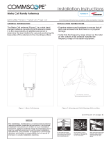
Fan Kit
Figure 3 shows the optional Fan Kit that is an integrated shroud that fits over a Fiber CAP L enclosure to
extend the upper ambient temper
ature range. The Fan Kit
• is IP55 rated
• increases the maximum operating temperature to 55°C (131°F)
• adds 3W power consumption to the Fiber CAP L; se
e "Required Antenna Distances” on page 16.
• is factory ins
talled but can be replaced in the field.
Fan Kit
Figure 3. CAP L with the Optional Fan Kit

CommScope Era
™
Fiber Low Power Carrier Access Point Installation Guide M0201ANC_uc
Page 8 © June 2019 CommScope, Inc.
Fiber CAP L Overview
Figure 4 shows the proprietary 8-pin Fan Interface port, which is only available on Fiber CAP L units that ship
with the factory-installed Fan Kit. If the Fiber CAP L being installed includes the Fan Kit option, the Fan
Interfa
ce port will be cabled to the Fan Kit at the factory. If the Fiber CAP L being installed does not inclu
de
the Fan Kit option, the Fan Interface port will be plugged.
Fan
Interface
port
Figure 4. Fan Interface Port
Mounting and Power Kits
CAP L Mounting and Power Kits are not included with the CAP L and must be ordered separately. Mounting
and Power Kits are described in the applicable installation process:
Table 3. Mounting and Power Kits
Mounting/Power Kit CommScope PN See
Flat Mounting Bracket Kit 7774353-xx "Mounting a CAP L with a Flat Mounting Bracket Kit” on page 25
Dual Mounting Kit 7815440-xx "Mounting Two CAP Ls with a Dual Mounting Kit” on page 31
Hybrid Fiber Splice Kit 7781091-xx "Mounting a CAP L with a Hybrid Fiber Spl
ice
Box Kit” on page 43
Power Supply/Hybrid Fiber Mounting Kit 7774354-xx "Mounting a CAP L with an AC/DC Power Supply Kit” on page 38
240W Local AC Power Supply Kit
"Mounting a CAP L with an AC/DC Power Supply Kit” on page 38
no AC Input Cord 7775087-xx
with AC Input Cord 7809798-xx
for Plenum Space 7809823-xx

M0201ANC_uc CommScope Era
™
Fiber Low Power Carrier Access Point Installation Guide
© June 2019 CommScope, Inc. Page 9
Fiber CAP L Overview
OCTIS Kits
All Fiber CAP Ls include one OCTIS
1
Kit for the primary interface to the Classic CAN or TEN. Regardless of
which OCTIS Kit ships with the CAP L, it will plug into Port 1 on the CAP L. You must order an additional OCTIS
Ki
t to cascade two CAP Ls, or to attach an auxiliary Ethernet device; which OCTIS Kit you should ord
er is
identified in Table 4.
Table 4. CAP L OCTIS Kits
Kit Name CommScope PN Description
Optical OCTIS Kit 7770612 This is the SFP+ connector that you use to cascade a Secondary Fiber
CAP L; one Optical OCTIS Kit ships with each Fiber CAP L. Use as
follows:
• Optical Port 1—to connect the CAP M to a Classic CAN or TEN.
• Optical Port 2—to cascade a second CAP M.
• SFP+ Module must be ordered separ
at
ely, it is not included as
part of the Optical OCTIS Kit.
• Ships with the following grommets:
– 6mm nominal diameter for use with cabl
es with OD range
from 4.8-5.8
– 7mm nominal diameter for use with cables with OD range
from 5.8-6.8
– 8mm nominal diameter for use with cables with OD range
from 6.8-7.8
Ethernet OCTIS Kit 7760652 This is the RJ-45 connector that you use to attach an auxiliary
Ethernet device. The Ethernet OCTIS Kit must be ordered
separately.
SFP+ Modules
The SFP+ Module installed in an OPT Card port is paired with another in Optical Port 1 of the Fiber CAP L. For
a complete list of available SFP+ Modules, refer to the Era™SolutionOrderingGuide.
1 OCTIS is a trademark of RADIALL.

CommScope Era
™
Fiber Low Power Carrier Access Point Installation Guide M0201ANC_uc
Page 10 © June 2019 CommScope, Inc.
Plan and Prepare for a Fiber CAP L Installation
PLAN AND PREPARE FOR A FIBER CAP L INSTALLATION
Do the following before beginning installation.
1 Review and know the information in "Maximum
Number of Fiber CAP Ls Supported in an Era System” on
page 10.
1 Rev
iew and know the information in "Cascade R
ules for Fiber CAP Ls” on page 11.
2 Review and know the information in "Saf
ely Working with Era Hardware” on page 12.
3 "Required Antenna Distances” on page 16.
4 "Determine the CAP L Installation Site” on page 17, which includes understanding and meeting
requirements for:
• "Recommended Tools and Material” on page 23
• "CAP L Weights” on page 21
• "Extended CAP L Temperature Operation” on page 22
• "CAP L Dimensions” on page 18.
5 Map out all
cable runs.
6 Identify and obtain all tools and mater
ials required to complete the installation as described in
"Recommended Tools and Material” on page 23.
7 Obtain any accessories required for this installation; see "CAP L Accessories and Options” on page 7.
8 "Unpack and Inspect the CAP L and Optional Accessories” on page 23.
Maximum Number of Fiber CAP Ls Supported in an Era System
When installing a Fiber CAP L, you must observe the following rules.
• SMF or MMF connects the Fiber CAP L via its Op
tical Port 1 to the OPT Card.
• You connect CAP Ls to a
n OPT Card installed in Slots L1, L2, L3, or L4 in the TEN or Classic CAN.
– Each OPT Card has four 10 Gbps ports (labeled 1 - 4) for
fiber connections.
– You can connect up to 4 CAP Ls
per OPT Card for a total of 16 Primary and 32 total, per TEN or Classic
CAN.
Fiber CAP Ls must be connected to OPT Cards installed in Slots L1, L2, L3, or L4 in a TEN or Classic CAN.
OPT Cards installed in WCS Slots L5 - L8 cannot be used to connect APs.

M0201ANC_uc CommScope Era
™
Fiber Low Power Carrier Access Point Installation Guide
© June 2019 CommScope, Inc. Page 11
Plan and Prepare for a Fiber CAP L Installation
Cascade Rules for Fiber CAP Ls
When cascading a Secondary Fiber CAP L or an external Ethernet device such as WiFi or an IP camera, you
must observe the following rules.
• I
n a cascade, the CAP L connected directly to the Classic CAN or TEN is the Primary Fiber CAP L, and the
CAP L that connects to the Primary Fiber CAP L is the Secondary Fiber CAP L.
• The cascaded unit must use the same transport type—you
cannot cascade a Copper CAP L to a Fiber
CAP L.
• The
total 320 MHz RF bandwidth is shared between the two cascaded units, but can be shared unevenly;
that is, with more bandwidth going to either the Primary or Secondary Fiber CAP L—either CAP L can
tran
smit all the 320 MHz RF bandwidth or any subset of it.
• The
Primary and Secondary Fiber CAP Ls power up as soon as power is applied to them. In a cascade, the
Era GUI discovers and readies the Primary CAP L for RF first, and then the Secondary CAP L will be
disco
vered and readied for RF. For information on the Power LED behavior, see "Powering on a Fiber
CAP L” on page 62.
• SMF or MMF from Optical Port 2
of the Primary Fiber CAP L connects to Optical Port 1 of the Secondary
Fiber CAP L.
• You can connect th
e following to the Primary Fiber CAP L
– a Secondary Fiber CAP L
– an
Ethernet device
– b
oth a Secondary Fiber CAP L (Port 2) and an Ethernet device (Aux Port).
• A
cascaded CAP L pair can support one auxiliary device; the auxiliary device must be connected to Port A
on the Primary Fiber CAP L, it cannot be connected to the Secondary CAP L.
• To
add a Secondary AP, you must add an Optical OCTIS kit to the Primary CAP L, see "OCTIS Kits” on
page 9.
• To
add an Ethernet device, you must add an RJ45 OCTIS kit to the Primary CAP L, see "OCTIS Kits” on
page 9.

CommScope Era
™
Fiber Low Power Carrier Access Point Installation Guide M0201ANC_uc
Page 12 © June 2019 CommScope, Inc.
Plan and Prepare for a Fiber CAP L Installation
Cat6A Cable Requirements for Ethernet Devices
If you connect an Ethernet device to a Fiber CAP L, you must observe the following rules.
• Plenum rated cable must be used whenever it is required by local electrical
codes.
• Shielded twisted pair is not required unless operating in a high RF
I/EMI environment.
• CommScope strongly recommends using fa
ctory terminated and tested Cat6A Patch Cord.
• 24 AWG Cat6A cabling is sufficient for the cable run between the
Fiber CAP L and the Ethernet device.
• The maximum attached cable length from Port A on the Fiber CAP L
to the Ethernet device is 3 meters (9.8
feet); see Figure 5.
From a Fiber CAP L to an Ethernet device,
Cat6A cannot exceed 3 meters (9.8 feet)
24 AWG Cat6A Cable
Fiber CAP L
Ethernet
Device
Figure 5. Maximum Cat6A Cable Length between a Fiber CAP L and an Ethernet Device
Safely Working with Era Hardware
The following sections provide important information that you should read and know before working with
any Era hardware. Observe all cautions and warnings listed in this section.
Health and Safety Precautions
A high leakage current ground (earth) connection to the Power Supply Unit (PSU) is essential before
making any other connections to the PSU.
Laser radiation. Risk of eye injury in operation. Do not stare into the laser beam; do not view the laser
beam directly or with optical instruments.
High frequency radiation in operation. Risk of health hazards associated with radiation from the
antenna(s) connected to the unit. Implement prevention measures to avoid the possibility of close
proximity to the antenna(s) while in operation.

M0201ANC_uc CommScope Era
™
Fiber Low Power Carrier Access Point Installation Guide
© June 2019 CommScope, Inc. Page 13
Plan and Prepare for a Fiber CAP L Installation
Property Damage Warnings
Keep operating instructions within easy reach and make them available to all users.
Only license holders for the respective frequency range are allowed to operate this unit.
Read and obey all the warning labels attached to the unit. Make sure that all warning labels are kept in a
legible condition. Replace any missing or damaged labels.
Make sure the unit's settings are correct for the intended use (refer to the manufacturer product
information) and regulatory requirements are met. Do not carry out any modifications or fit any spare
parts, which are not sold or recommended by the manufacturer.
General Installation Safety Requirements
Wet conditions increase the potential for receiving an electrical shock when installing or using electrically
powered equipment. To prevent electrical shock, never install or use electrical equipment in a wet
location or during a lightning storm.
This system is a RF Transmitter and continuously emits RF energy. Maintain a minimum clearance from
the antenna as specified in Table 6 while the system is operating. Whenever p
ossible, power down the
CAP
L before servicing the antenna.
Do not remove caps from any of the connectors until instructed to do so.
The CAP L is to be used only with CommScope (NEC Class 2) or Limited Power Source Era Subrack, or
equivalent.
Guard Against Damage from Electro-Static Discharge
Electro-Static Discharge (ESD) can damage electronic components. To prevent ESD damage, always wear
an ESD wrist strap when working with Era hardware components. Not all Era hardware requires
grounding. For those Era hardware components for which grounding is required, connect the ground wire
on the ESD wrist strap to an earth ground source before touching the Era component. Wear the wrist
strap the entire time that you work with the Era hardware.

CommScope Era
™
Fiber Low Power Carrier Access Point Installation Guide M0201ANC_uc
Page 14 © June 2019 CommScope, Inc.
Plan and Prepare for a Fiber CAP L Installation
Compliance
1 Notice: For installations, which have to comply with FCC RF exposure requirements, the antenna
selection and installation must be completed in a way to ensure compliance with those FCC requirements.
Depending on the RF frequency, rated output power, antenna gain, and the loss between the repeater and
antenna, the minimum distance D to be maintained between the antenna location and human beings is
calculated according to this formula:
]/[
][
][
2
4
cmmW
mW
cm
PD
P
D
where
• P (mW) is the radiated power at the
antenna, i.e. the max. rated repeater output power in addition to
the antenna gain minus the loss between the repeater and the antenna.
• PD (mW/cm²) is the allowed Power D
ensity limit acc. to 47 CFR 1.1310 (B) for general population /
uncontrolled exposures which is
– f (MHz) / 1500 for frequencies from 300MHz to 1500MHz
– 1 for frequencies from 1500MHz to 100,000MHz
R
F exposure compliance may need to be addressed at the time of lice
nsing, as required by the responsible
FCC Bureau(s), including antenna co-location requirements of 1.1307(b)(3).
2 Notice: Fo
r installations which have to comply with European EN50385 exposure compliance
requirements, the following Power Density limits/guidelines (mW/cm²) according to ICNIRP are valid:
• 0.2 for frequencies from 10 MHz to 400 MHz
• F (MHz) / 2000 for frequencies from 400 MHz to 2 GHz
• 1 for frequencies from
2 GHz to 300 GHz
3 Notice: Installation of th
is equipment is in full responsibility of the installer, who has also the
responsibility, that cables and couplers are calculated into the maximum gain of the antennas, so that this
value, which is filed in the FCC Grant and can be requested from the FCC data base, is not exceeded. The
industrial boosters are shipped only as a naked booster without any installation devices or antennas as it
needs for professional installation.
4 Notice: Fo
r installations which have to comply with FCC/ISED requirements:
English:
This device complies with FCC Part 15. Operation is
subject to the following two conditions: (1) this
device may not cause interference, and (2) this device must accept any interference, including
interference that may cause undesired operation of the device.
This device complies with Health Canada's Safety Code. The installer of
this device should ensure that RF
radiation is not emitted in excess of the Health Canada's requirement. Information can be obtained at
http://www.hc-sc.gc.ca/ewh-semt/pubs/r
adiation/radio_guide-lignes_direct-eng.php.
Changes or modifications not expressly approved by the party responsible f
or compliance could void the
user's authority to operate the equipment.
AntennaStmtforISED:
This
device has been designated to o
perate with the antennas having a maximum gain of 9 dBi. Antennas
having a gain greater than 9 dBi are prohibited for use with this device without consent by ISED
regulators. The required antenna impedance is 50 ohms.
The antenna(s) used for this transmitter must be installed to pro
vide a minimum separation distance (as
specified in Table 6) from all persons and must not be co-located or operating in conjunction with any

M0201ANC_uc CommScope Era
™
Fiber Low Power Carrier Access Point Installation Guide
© June 2019 CommScope, Inc. Page 15
Plan and Prepare for a Fiber CAP L Installation
other antenna or transmitter. Users and installers must be provided with antenna installation
instructions and transmitter operating conditions for satisfying RF exposure compliance.
French:
Cet appareil est conforme à F
CC Partie15. Son utilisation est soumise à Les deux conditions suivantes: (1)
cet appareil ne peut pas provoquer d'interférences et (2) cet appareil doit accepter Toute interférence, y
compris les interférences qui peuvent causer un mauvais fonctionnement du dispositif.
Cet appareil est conforme avec Santé Ca
nada Code de sécurité 6. Le programme d'installation de cet
appareil doit s'assurer que les rayonnements RF n'est pas émis au-delà de I'exigence de Santé Canada. Les
informations peuvent être obtenues:
http://www.hc-sc.gc.ca/ewh-semt/pu
bs/radiation/radio_guide-lignes_direct-eng.php
Les changements ou modifications non expressément approuvés par la par
tie responsable de la
conformité pourraient annuler l'autorité de l'utilisateur à utiliser cet équipement.
AntenneStmtpo
urISDE:
Ce dispositif a été dési
gné pour fonctionner avec les antennes ayant un gain maximal de 9 dBi. Antennes
ayant un gain plus grand que 9 dBi sont interdites pour une utilisation avec cet appareil sans le
consentement des organismes de réglementation d'ISDE. L'impédance d'antenne requise est 50 ohms.
L'antenne (s) utilisé
pour cet émetteur doit être installé pour fournir une distance de séparation minimale
(comme indiqué dans le Table 6) par rapport à tou
te personnes et ne doit pas être co-localisées ou
opérant en conjonction avec une autre antenn
e ou émetteur. Les utilisateurs et les installateurs doivent
être fournis avec des instructions d'installation de l'antenne et des conditions de fonctionnement de
l'émetteur pour satisfaire la conformité aux expositions RF.
5 Noti
ce: The unit complies with Overvoltage Category II. It also complies with the surge requirement
according to EN 61000-4-5 (fine protection); however, installation of an additional medium (via local
supply connection) and/or coarse protection (external surge protection) is recommended depending on
the individual application in order to avoid damage caused by overcurrent.
For Canada and US, components used to
reduce the Overvoltage Category shall comply with the
requirements of IEC 61643-series. As an alternative, components used to reduce the Overvoltage
Category may comply with ANSI/IEEE C62.11, CSA Certification Notice No. 516, CSA C22.2 No. 1, or UL
1449. Suitability of the component for the application shall be determined for the intended installation.
6 Noti
ce: Corresponding local particularities and regulations must be observed. For national deviations,
please refer to the respective documents included in the manual CD that is delivered with the unit.
7 Note:For a Class
B digital device or peripheral:
This equipment has been tested and found to comply with the limits
for a Class B digital device, pursuant
to part 15 of the FCC Rules. These limits are designed to provide reasonable protection against harmful
interference in a residential installation. This equipment generates, uses and can radiate radio frequency
energy and, if not installed and used in accordance with the instructions, may cause harmful interference
to radio communications. However, there is no guarantee that interference will not occur in a particular
installation. If this equipment does cause harmful interference to radio or television reception, which can
be determined by turning the equipment off and on, the user is encouraged to try to correct the
interference by one or more of the following measures:
• Reorient or relo
cate the receiving antenna.
• I
ncrease the separation between the equipment and receiver.
• C
onnect the equipment into an outlet on a circuit different from that to which the receiver is
connected.
• Consul
t the dealer or an experienced RF technician for help.

CommScope Era
™
Fiber Low Power Carrier Access Point Installation Guide M0201ANC_uc
Page 16 © June 2019 CommScope, Inc.
Plan and Prepare for a Fiber CAP L Installation
8 Notice: For a Class A digital device or peripheral.
This equipment has been tested and found to comply with the limits for
a Class A digital device, pursuant
to Part 15 of the FCC Rules. These limits are designed to provide reasonable protection against harmful
interference when the equipment is operated in a commercial environment. This equipment generates,
uses, and can radiate radio frequency energy and, if not installed and used in accordance with the
instruction manual, may cause harmful interference to radio communications. Operation of this
equipment in a residential area is likely to cause harmful interference in which case the user will be
required to correct the interference at his own expense.
9 Note:T
his unit complies with European sta
ndard EN60950-1 / EN62368-1.
Equipment Symbols Used / Compliance
Please observe the meanings of the following symbols used in our equipment and the compliance warnings
listed in Table 5.
Table 5. Compliance Labels
Symbol Compliance Meaning
— FCC
For industrial (Part 20) signal booster:
WARNING: This is NOT a CONSUMER devi
ce. It is designed for installation by FCC LICENSEES and
QUALIFIED INSTALLERS. You MUST have an FCC LICENSE or express consent of an FCC Licensee to
operate this device. Unauthorized use may result in significant forfeiture penalties, including
penalties in excess of $100,000 for each continuing violation.
For (Part 90) signal booster:
WARNING: This is NOT a CONSUMER devi
c
e. It is designed for installation by FCC LICENSEES and
QUALIFIED INSTALLERS. You MUST have an FCC LICENSE or express consent of an FCC Licensee to
operate this device. You MUST register Class B signal boosters (as defined in 47 CFR 90.219) online
at www.fcc.gov/signal-boosters/registration. Unauthorized use may result in significant forfeiture
penalties, including penalties in excess of $100,000 for each continuing violation.
— ISED
WARNING: This is NOT a CONSUMER device.
I
t is designed for installation by an installer approved
by an ISED licensee. You MUST have an ISED LICENCE or the express consent of an ISED licensee to
operate this device.
AVERTISSEMENT: Ce produit N'EST PAS un appareil de CONSOMMATION. Il est conçu pour être
installé par un installateur approuvé par un titulaire de licence d'ISDE. Pour utiliser cet appareil,
vous DEVEZ détenir une LICENCE d'ISDE ou avoir obtenu le consentement exprès d'un titulaire de
licence autorisé par ISDE.
CE
To be sold exclusively to mobile operators or
authorized installers - no harmonized frequency
bands, operation requires license. Intended use: EU and EFTA countries.
Indicates conformity with the RED directive 2014/53/EU and/or RoHS di
rective 2011/65/EU.
Required Antenna Distances
Table 6. Required Antenna Distances
CAP L Model
Antenna gain
with
out cable
loss [dBi]
Minimum Distance Between Antennas and A
ll Persons
FC
C ISED
Meters Inches Meters Inches
CAP L 7/80-85/17E/19 9 .176 6.9 .256 10.1
CAP L 17E/17E/19/19 9 .218 8.58 .259 10.2
CAP L 17E/17E/23/23 9 .169 6.65 .237 9.33
CAP L 17E/19/23/25TDD 9 .178 7.02 .251 9.88
/