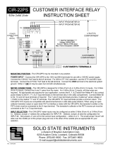
FUSES - Fuse F5 in the utility's compartment is coordinated (in series) with the customer's fuse F1. Fuses F6
is similarly coordinated with F2. F1 and F2 are factory-equipped at 1/4th Amp (Max 1/2A). F5 and F6 are
factory equipped at 1/2 Amp (Max 3/4A). F5 and F6 are designed to protect the CIR-13PS's circuit boards in
the event that fuses larger than 1/2 Amp are used by the customer in the F1 and F2 positions. F1 and F2 may
be sized up to 1/2 Amp but must be at least 1/8th Amp less than the size of F5 and F6 respectively. F3 which
protects Utility output #3, is also factory equipped at 1/2 Amp. Maximum fuse ratings are designated on the
silkscreen under or adjacent to each fuse position.
CUSTOMER OUTPUTS - Two outputs are provided for CUSTOMER use. The terminals for these two outputs
are located in the bottom of the enclosure in the customer compartment and are marked K1, Y1 and Z1 for
Output #1 and K2, Y2, and Z2 for Output #2. Each K-Y input (connection between the K and Y input terminals)
will result in a closure of the K-Y contacts of all outputs. A K-Z input (connection between the K and Z input
terminals) will result in a closure (continuity) of the K-Z contacts of all outputs. Outputs are dry-contact type and
must be provided with an external voltage of up to 250VAC/VDC on the K terminal by the customer's
equipment. Maximum current through the solid state switch is 500mA. Arc suppression for the contacts of the
solid state relays are provided internally. There is approximately 2.5 ohms of on-state resistance across the
relay outputs.
UTILITY OUTPUT - One output is provided for UTILITY use and is located in the top of the enclosure in the
utility compartment. It is marked K3, Y3 and Z3. Each K-Y input (connection between the K and Y input
terminals) will result a closure of the K-Y contact of the output. A K-Z input (connection between the K and Z
input terminals) will result in a closure of the K-Z contact of the output. Outputs are dry-contact type and must
be provided with an external voltage of up to 250VAC/VDC on the K terminal by the customer's equipment.
Maximum current through the solid state switch is 500mA. Arc suppression for the contacts of the solid state
relays are provided internally. There is approximately 2.5 ohms of on-state resistance across the relay outputs.
SOLID STATE INSTRUMENTS
a division of Brayden Automation Corp.
6230 Aviation Circle, Loveland, Colorado 80538
Phone: (970)461-9600
MAXIMUM POWER DISSIPATION OF OUTPUTS - Output devices are rated at a maximum of 50VA. Care
should be taken to insure that the wetting voltage used across the output device times the current (or burden) of
the input of the downstream device, does not exceed the maximum power output dissipation of 50W. Normally
this is not a problem since most downstream instrumentation devices are high impedience and present a very
low burden, usually less than 10mA. For example, if 240VAC is used, the maximum allowable current across
the output is 208mA. If 12VDC is used, the maximum current allowable across the output is approximately
4.15A, however 4.15 Amps is clearly beyond the 1/2A rating of the device. Therefore, the maximum
dissipation when using 12V is 6VA since the current is limited to 1/2 amp. Calculate the maximum current using
the following formula: 50Watts / Voltage = Max. Current (burden). Adjust the voltage or current used across
the output to insure that the maximum power dissipation, voltage and current maximums are not exceeded.


