SSI CIR-24PS User manual

Type
User manual

This manual is also suitable for

SSI CIR-24PS is a versatile customer interface relay designed to provide isolated outputs for metering applications. It features four three-wire isolated outputs rated at 250VAC/VDC MAX and current limited to 500mA (1/2 Amp) each. Each output can be configured for either long or short pulse output mode, allowing for flexibility in adapting to different downstream devices. The CIR-24PS also includes two customer outputs and two utility outputs for added functionality. With its auto-ranging power supply from 120V to 277VAC, the CIR-24PS can be easily integrated into various electrical systems.

SSI CIR-24PS is a versatile customer interface relay designed to provide isolated outputs for metering applications. It features four three-wire isolated outputs rated at 250VAC/VDC MAX and current limited to 500mA (1/2 Amp) each. Each output can be configured for either long or short pulse output mode, allowing for flexibility in adapting to different downstream devices. The CIR-24PS also includes two customer outputs and two utility outputs for added functionality. With its auto-ranging power supply from 120V to 277VAC, the CIR-24PS can be easily integrated into various electrical systems.

SOLID STATE INSTRUMENTS
a division of Brayden Automation Corp.
6230 Aviation Circle, Loveland, Colorado 80538
Phone: (970)461-9600
E-mail:support@solidstateinstruments.com
CUSTOMER INTERFACE RELAY
INSTRUCTION SHEET
Z
1
Y
1
K
1
K
POWER
CONNECTIONS
MOUNTING POSITION - The CIR-24PS may be mounted in any position.
POWER INPUT - The CIR-24PS features an auto-ranging power supply from 120V to 277VAC. Connect the "hot"
lead to the LINE terminal. Connect the "neutral" lead to the NEU terminal. Connect the GND terminal to the
electrical system ground. If no true neutral exists at the meter, connect NEU and GND terminals both to Ground.
***The CIR-24PS must be wired Phase-to-Neutral, NOT Phase-to-Phase.***
METER CONNECTIONS - The CIR-24PS is designed for 2-Wire (Form A) or 3-Wire (Form C) inputs. For 2-Wire
(Form A) inputs, connect the K and Y wires from the meter. For 3-Wire (Form C) inputs, all three wires are
required. As appropriate and required for your application, connect the K, Y, & Z leads from Meter #1's dry contact
pulse initiator to the K1, Y1, & Z1 input terminals on the terminal strip in the utility compartment. Connect Meter #2
to K2, Y2 and Z2 input terminals of Input #2. The Y and Z input terminals provide a "pulled up" sense voltage of
+13VDC to the meters' "Y" and "Z" terminals. The CIR-24PS' "K" input terminals provide a common return. The
CIR-24PS' KYZ inputs are compatible with electromechanical or solid state pulse initiators. When using an open-
collector transistor output or open-drain FET to interface a meter with the CIR-24PS, the transistor's emitter or the
FET's drain must be connected to the K input terminal. The transistor's collector or the FET's source pin must be
connected to the Y or Z input terminals.
Y
CUSTOMER'S TERMINALS
1/4 AMP
Fuse
INPUT FROM METER #1
ZK
UTILITY'S
COMPARTMENT
CUSTOMER'S
COMPARTMENT
LED's
RED GRN
F1
F3
L
I
N
E
N
E
U
INPUT FROM METER #2
F2
F4
K
2
F5
G
N
D
YZ
Y
2
Z
2
1/2A
TB1
Input
Form/
Output
Mode
Select
Jum-
pers
RED GRN
1/4 AMP
Fuse
INPUT
#2
INPUT
#1
Rev. 10/22/2022
OUTPUT #1
OUTPUT #2
P/N: 05524-97006B
KYZ
OUTPUT
#3
KYZ
OUTPUT
#4
OUTPUT #4
OUTPUT #3
F6
1/2A
1/2A
1/2A
TB2
INPUT SELECTION - The CIR-24PS' meter inputs may be configured as either 2-Wire (Form A) or 3-Wire (Form
C). Selector Jumper J1 selects the configuration for INPUT #1. Selector Jumper J2 sets the configuration for
INPUT #2. Set jumpers J1 and J2 for the correct input configuration -- either A or C. The small jumper "shunt" will
slide over the middle pin of the jumper plug and one or the other of the outside pins as appropriate for your
selection.
CA
SL
CA
SL
J1
J2
J3
J4
A
B
Out 1
A
B
A
B
AB
Out 2
Out 3
Out 4
Output
Select
Selector
Switches
***** OUTPUT RATINGS *****
Voltage: 250VAC/VDC
Current: 250mA (1/4th Amp)
Max. Power Dissipation: 50VA
CIR-24PS
Elite Solid State
A5 Hardware
FUSES - Fuse F5 in the utility's compartment is coordinated (in series) with the customer's fuse F1. Fuse F6 is
similarly coordinated with F2. F1 and F2 are factory-equipped at 1/4th Amp. F5 and F6 are factory equipped at
1/2 Amp. F5 and F6 are designed to protect the CIR-24PS's circuit boards in the event that fuses larger than 1/
2 Amp are used by the customer in the F1 and F2 positions. F3 and F4, which protect Utility outputs #3 and #4,
are also factory equipped at 1/2 Amp. Maximum fuse ratings are designated on the silkscreen under or
adjacent to each fuse position.
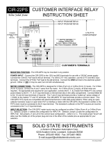
CUSTOMER OUTPUTS - Two outputs are provided for CUSTOMER use. The terminals for these two outputs
are located in the bottom of the enclosure in the customer compartment and are marked K1, Y1 and Z1 for
Output #1 and K2, Y2, and Z2 for Output #2. Each K-Y input (connection between the K and Y input terminals)
will cause a K-Y output of the same channel. A K-Z input (connection between the K and Z input terminals) will
result in a K-Z output. Outputs are dry-contact type and must be provided with an external voltage of up to
250VAC/VDC on the K terminal by the customer's equipment. Maximum current through the solid state switch
is 500mA. Arc suppression for the contacts of the solid state relays are provided internally. There is
approximately 2.5 ohms of on-state resistance across the relay outputs.
UTILITY OUTPUTS - Two outputs are provided for UTILITY use, one corresponding to each input. The output
terminals are located in the top of the enclosure in the utility compartment and are marked K3, Y3 and Z3 for the
first output and K4, Y4, and Z4 for the second output. Each K-Y input (connection between the K and Y input
terminals) will cause a K-Y output of the same channel. A K-Z input (connection between the K and Z input
terminals) will result in a K-Z output. Outputs are dry-contact type and must be provided with an external
voltage of up to 250VAC/VDC on the K terminal by the customer's equipment. Maximum current through the
solid state switch is 500mA. Arc suppression for the contacts of the solid state relays are provided internally.
There is approximately 2.5 ohms of on-state resistance across the relay outputs.
OUTPUTS - Four three-wire isolated outputs are provided on the CIR-24PS, with output terminals K1, Y1 & Z1;
K2, Y2, & Z2; K3, Y3 & Z3; and K4, Y4 & Z4. Each output is rated at 250VAC/VDC MAX and current limited to
500mA (1/2 Amp). Arc suppression for the contacts of the solid state relays are provided internally. Each relay
must be assigned to one of the two input channels. Using the A-B Selector Switches, select "A" for input
number 1, or "B" for input number 2. Each relay's output will follow the input selected. The CIR-24PS' outputs
may be configured for either Long or Short output pulses. Selector Jumper J3 selects the long or short output
configuration for all outputs set to INPUT #1. Selector Jumper J4 sets the long or short output configuration for
all outputs set to INPUT #2. Put the Jumper Plug in the correct position for the output type desired. See Page 3
for more information on Long and Short output modes.
SOLID STATE INSTRUMENTS
a division of Brayden Automation Corp.
6230 Aviation Circle, Loveland, Colorado 80538
Phone: (970)461-9600
MAXIMUM POWER DISSIPATION OF OUTPUTS - Output devices are rated at a maximum of 50VA. Care
should be taken to insure that the wetting voltage used across the output device times the current (or burden) of
the input of the downstream device, does not exceed the maximum power output dissipation of 50W. Normally
this is not a problem since most downstream instrumentation devices are high impedience and present a very
low burden, usually less than 10mA. For example, if 240VAC is used, the maximum allowable current across
the output is 208mA. If 12VDC is used, the maximum current allowable across the output is approximately
4.15A, however 4.15 Amps is clearly beyond the 1/2A rating of the device. Therefore, the maximum
dissipation when using 12V is 6VA since the current is limited to 1/2 amp. Calculate the maximum current using
the following formula: 50Watts / Voltage = Max. Current (burden). Adjust the voltage or current used across
the output to insure that the maximum power dissipation, voltage and current maximums are not exceeded.
WORKING WITH THE CIR-24PS RELAY
T1
T2
Figure 2: 2-Wire or 3-Wire SHORT Output Operation
K-Y Out
Kin-Zin*
Kin-Yin
OPERATING MODES: The CIR-24PS Repeating Pulse Relay allows the output to be
configured for either the "Long" or "Short" pulse output mode using Jumpers J3 and J4. In
the Long mode, the output(s) assigned to a particular input will simply follow that input.
Output pulse widths are equal to input pulse widths. With the "long" output configuration
selected, pulse speeds of up to 72,000 pulses per hour (~20/sec) are possible. Figure 1
below shows the timing diagram for the "long" output mode.
If the input pulse rate is greater than 9 pulses per second or if pulses of 100mS are too short
for the receiving equipment, it is recommend that the LONG pulse output mode be used.
Contact the factory for technical support at (888)272-9336.
Figure 1: 2-Wire or 3-Wire LONG Output Operation
Kin-Yin
K-Z Out
K-Y Out
Open
Open
Closed
Open
Close
d
Closed
Open
Open
Closed
Open
Closed
Closed
Kin-Zin*
Closed
In the Short output mode, shown in Figure 2 below, an output pulse (K-Y closure) with a fixed
width (T1) of 100mS occurs each time the input is triggered. Correspondingly, the K-Z output
opens for 100mS (T2) each time the input is triggered. In the "short" mode, the output pulse
rate is limited to about 9 pulses per second, or about 32,400 pulses per hour.
Open
Closed
K-Z Out
Open
* Zin is not used in the 2-wire (Form A) input mode.
  • Page 1 1
  • Page 2 2
  • Page 3 3

SSI CIR-24PS User manual

Type
User manual
This manual is also suitable for

SSI CIR-24PS is a versatile customer interface relay designed to provide isolated outputs for metering applications. It features four three-wire isolated outputs rated at 250VAC/VDC MAX and current limited to 500mA (1/2 Amp) each. Each output can be configured for either long or short pulse output mode, allowing for flexibility in adapting to different downstream devices. The CIR-24PS also includes two customer outputs and two utility outputs for added functionality. With its auto-ranging power supply from 120V to 277VAC, the CIR-24PS can be easily integrated into various electrical systems.

Ask a question and I''ll find the answer in the document

Finding information in a document is now easier with AI