Solid State Instruments RTR-2C Operating instructions

Type
Operating instructions

Solid State Instruments RTR-2C is a high-speed pulse isolation relay designed for use with electric, water, or gas meters. It features two dry-contact solid-state outputs, a built-in noise rejection algorithm to distinguish between valid pulses and noise, and configurable input and output pulse durations. The RTR-2C can be used in various applications, including pulse counting, data logging, and remote monitoring.

Solid State Instruments RTR-2C is a high-speed pulse isolation relay designed for use with electric, water, or gas meters. It features two dry-contact solid-state outputs, a built-in noise rejection algorithm to distinguish between valid pulses and noise, and configurable input and output pulse durations. The RTR-2C can be used in various applications, including pulse counting, data logging, and remote monitoring.

HIGH SPEED PULSE ISOLATION
RELAY INSTRUCTION SHEET
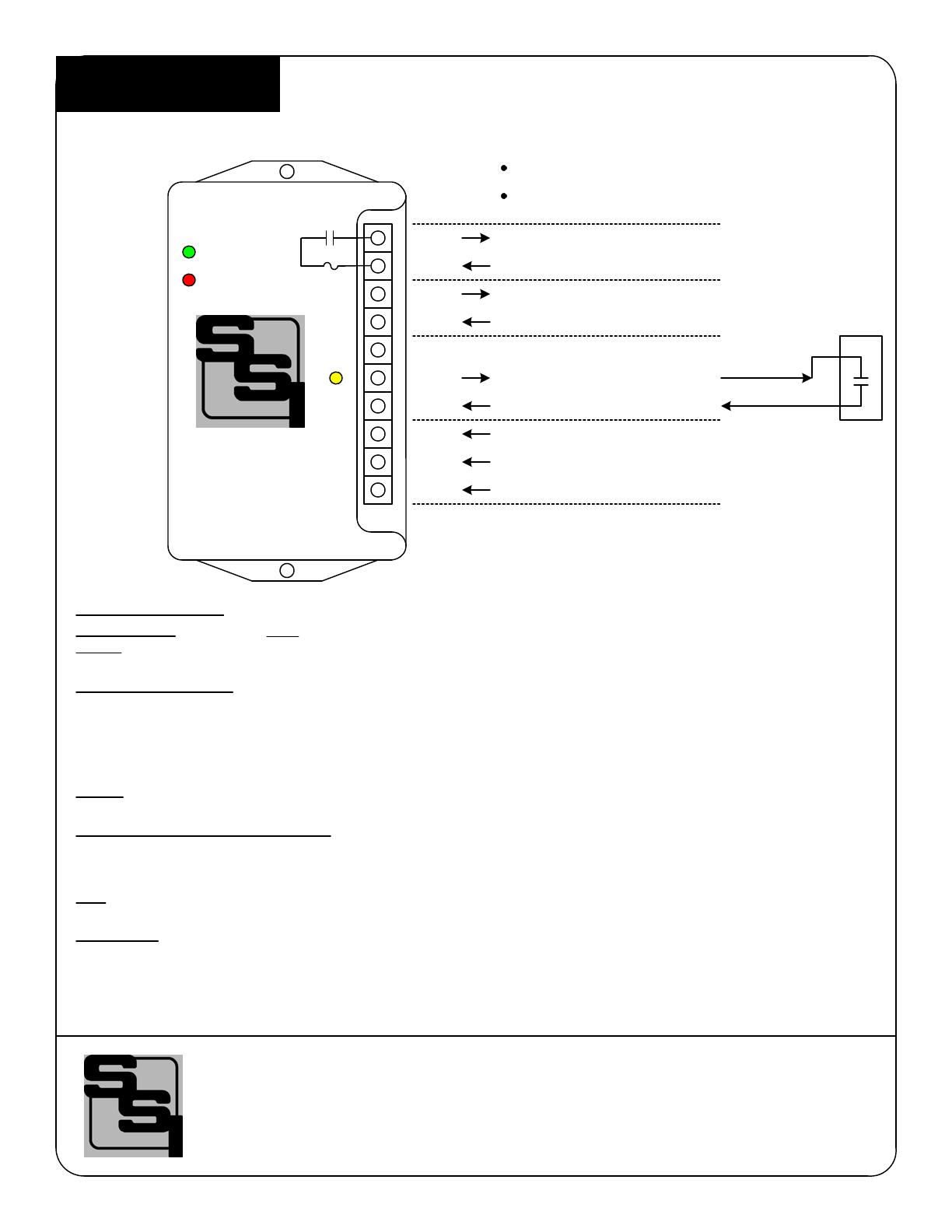
OUTPUT #2
CONNECTIONS TO METER
POWER SUPPLY
INPUT
MOUNTING POSITION - The RTR-2C may be mounted in any position.
POWER INPUT - Connect the "Hot" lead to the L1 terminal. The power supply is autoranging from 120 to 277VAC. Connect the
Neutral power supply lead to the NEU terminal. Connect the electrical system ground to the GND terminal. The unit must be
grounded for proper operation.
METER CONNECTIONS - The RTR-2C's Kin and Yin terminals are connected to the meter. The RTR-2C's Yin terminal is the
"pulled-up" +13VDC source which is connected to the "+" input of the meter. The Kin terminal is the system common return or
ground. Upon a closure of the meter's pulse switching device, the +13VDC Yin input line is pulled down to ground. The Amber
LED will light indicating that a pulse has been received. If the width of the input pulse is very short, the Amber LED may be
difficult to see. Assuming the pulse meets the input criteria, the Green LED will light, indicating that a pulse output switch has
closed, and thus a pulse output has occurred. Shielded cable is highly recommended between the meter and the RTR-2C input.
FUSES - The fuses F1 and F2 are type 3AG and may be up to 1/10 Amp in size. Two 1/10 Amp fuses are supplied standard with
the unit unless otherwise specified.
INPUT and OUTPUT CONFIGURATION - Under the RTR-2C's cover in the center of the board just below the lower fuse (F1) is
a 8-position DIP switch labeled S1. This DIP switch allows the input and output timing configurations to be set. Switch #1 sets
the Normal or Fixed output mode. Use the Normal mode to have the output pulse length match the input pulse length. The
normal mode is generally necessary for high speed and the length of the pulse varies with pulse speed. Use the Fixed mode for a
fixed output pulse width. Switches S5, S6 and S7 set the input filtering time. Any pulse less than the selected input filtering time
will be ignored and considered to be noise. Switches S2, S3 and 4 set the output pulse width if the Fixed mode is selected.
+13VDC pulled-up voltage TO meter
OUTPUT #1
NEUTRAL
SOLID STATE INSTRUMENTS
a division of Brayden Automation Corp.
6230 Aviation Circle, Loveland Colorado 80538
Phone: (970)461-9600
Revision: 3/16/2022 P/N: 05204-97006C3
K
Y
Common return FROM meter
RTR-2C
C-Series
Standard Solid State
120-277V HOT
GROUND
GAS/H2O
METER
-
+
Y2
K2
Yin(+)
Kin(-)
L1
Y1
K1
Typical Form A
dry contact
Output circuit
F2
NEU
GND
Y2K2YinKinL1 Y1K1NEUGND XVIO
XVin
Output LED
Input
LED
N/C
Pulse
GND
Dry Contact compatible Input
Two dry-contact solid state outputs
See page 3 &4 of this sheet for additional information on selecting system settings. Transient suppression for the contacts of the
solid state relay is provided internally.
TEST MODE - The RTR-2C includes a test mode to be able to detect very short width input pulses. Enable the test mode by
putting Switch 8 of S1 in the UP position. In this position, once a pulse is detected, it will latch on the RED LED to indicate that
a pulse has been detected. Cycle the power to reset the LED. The test mode will detect pulses down to 25 microseconds. Put
Switch 8 in the DOWN position for normal operation and reset the RED LED.
Pulse Detect LED (Test)
Output Overflow (Normal)
WORKING WITH THE RTR-2C RELAY
the normal pulses with time durations of T1and T4 will cause an output. The short pulse of time
duration T2 and the noise with duration T3 will be rejected because the length of time (pulse
width) is too short, even though the voltage is of sufficient magnitude. The time T4 could be
many times as long as T1 and it would still be a valid time pulse since it has met the minimum
time requirement. The time duration of 20 milliseconds (max) has been chosen as the factory-
set default value since one cycle of the 60 hertz AC line frequency represents 16.67
milliseconds. Most induced noise and arcing discharges do not last longer than this, while
most contact closures are a great deal longer. The minimum filter time of the incoming pulse
may be modified by changing switches S1.5, S1.6 and S1.7. See Table 2 on Page 3 for input
filtering times.
OUTPUT PULSE DURATION: The RTR-2C can output two types of pulses - normal or fixed -
depending upon the position of switch S1.1. In the UP position, the RTR-2C outputs a "fixed"
pulse which has a duration determined by the position of switches S1.2, S1.3 and S1.4. Once
a valid pulse has been qualified, the output pulse will be set and the specified output time will
begin timing out. See Table 3 on page 3 for the selectable output pulse lengths. If switch S1.1
is in the UP position and the incoming pulse is of sufficient time duration to be a valid pulse, but
is less than 100 milliseconds, for example, the output time period will still be 100 milliseconds.
Thus, the RTR-2C can be used as a "pulse stretcher". In the DOWN position, the RTR-2C
outputs a "normal" (variable width) pulse which is the same duration as the valid input pulse.
Thus, in fixed mode, the maximum pulse rate is dependent on the positions of switches S1.2
through S1.4. If no switches are switched up, the RTR-2C will default to the normal output
mode, 20mS input time, and output will mirror the input pulse length.
T1 T2 T3 T4
Normal
Pulse
Short
Pulse Noise Normal
Pulse
BLOCKING NOISE: The RTR-2C has a built-in noise rejection software algorithm for
detecting valid pulses from a sending source. The algorithm accomplishes this by measuring
the time the input
pulse is present. If the
input pulse is present
for less than the
specified time (in
milliseconds) as
determined by the
position of switches
S1.5, S1.6 and S1.7, it
is assumed to be
noise. An input equal
or longer in duration
than the specified time
is classified as a valid
input and an output
will occur. In the
illustration to the left,
INPUT DEBOUNCE TIMES - The RTR-2C contains eight different input debouncing time options. A
pulse received at the RTR-2C's input must be present for at least the specified amount of time to be
considered a valid pulse. Minimum pulse times can be set in the following times:
25uS,50uS,100uS, 200uS 500uS, 1mS, 5mS or 20mS. For most electric meter pulse applications,
the 20mS input time will be satisfactory. For high-speed pulse applications with water or gas
meters, the minimum input time may need to be reduced depending on the meter's output pulse
width. Table 2 below shows how to set switches S1.5 thru S1.7 for the selected time.
CONFIGURING THE RTR-2C RELAY
S1.5 S1.6 mS/uS
20mS
5mS
1mS
50uS
Table 2
*
23451
Normal or Fixed Mode
Dip Switch S1
Input Filter Time (mS/uS)
Output Pulse Width (mS)
Up
DwnDwn
Dwn
UpDwn
Up Up
S1.1 Mode
Normal (Variable)
Fixed
Table 1
*
Dwn
OUTPUT MODE - Set the Output Mode to either the Normal (output pulse width equal to input
time) or Fixed with Switch S1.1 as shown in Table 1.
Up
67
Test Mode
25uS
Up
100uS
Up Up Dwn
Dwn
200uS
Up Dwn Up
500uS
DwnUp
S1.7
DwnDwn Up
Dwn
Up
Dwn
8
* Note: Switches S1.1-S1.8 come factory-set to the "DOWN" position.
USING THE TEST MODE - Many water and gas meters have very high pulse rates with pulse
durations or widths that are very short or narrow. Sometimes it is very difficult to observe pulses
being received from the water or gas meter. To assist with detecting short pulses, the RTR-2C
has a built-in test mode. The purpose of test mode is to detect a pulse from the meter and latch
the RED LED on to let the installer know that a pulse has been received by the RTR-2C, even
though it cannot be seen on the YELLOW LED since it's on time is so short. Once the RTR-2C
has detected a pulse and latched the RED LED on, dip switch S1.8 can be returned to the down
position to reset the RED LED to off.
Alternately the RTR-2C can have its power cycled to reset the RED LED to continue monitoring
for the next valid pulse.
In test mode, pulses continue to be processed and outputted.
CONFIGURING THE RTR-2C RELAY (con't)
Mode
Operating Mode
Test Mode
Table 4
*
Dwn
TEST MODE - Set the Test Mode switch to either the operating mode or the test mode as
indicated by Table 4.
Up
FIXED MODE OUTPUT PERIOD - When S1.1 is UP and selecting the fixed output pulse mode, the
duration of the output time can be selected by using dip switches S1.2 thru S1.4. Output times are
selectable as follows: 5mS, 10mS, 20mS, 50mS, 100mS, 200mS, 500mS and 1000mS. The
receiving equipment may require pulses to be of a given minimum length to be considered a valid
pulse. If input pulses are received while a fixed output pulse is timing out, the RTR-2C will store the
received pulse(s) in an overflow register and output them as soon as the current pulse has timed
out. The time between pulses is the same as the specified pulse time, giving a 50/50 duty cycle. A
maximum of 65,535 output pulses can be stored. If the pulse rate from the meter is too high, pulses
may be lost in the fixed mode if the output pulse register exceeds the 65,535 pulse maximum. In
that case, the normal mode will have to be used. When in the operational mode, if stored pulses
are present in the overflow register the RED LED will light.
Up
DwnDwn
Dwn Dwn
Up
Up Up
5
100
200
500
Table 3
* Note: Switches S1.1-S1.8 come factory-set to the "DOWN" position.
*
Dwn
10
50
20
1000
Dwn Dwn
Dwn
Up
Up
Up
Up
Up
Dwn
Dwn
Up
Up Up
Dwn
Dwn
S1.3S1.2 mSS1.4
S1.8
RTR-2C Wiring Diagram
s
3/16/2022 N/A
C3
DATE ORIGINAL
LATEST REVISION
SCALE
JOB NO.
REVISIONS
NO. DATE DESCRIPTION
WHB
DRAWNCHECKED
RTR-2C Repeating
Pulse Relay
Wiring Diagram
Brayden Automation Corp./
Solid State Instruments div.
6230 Aviation Circle
Loveland, CO 80538
(970)461-9600
www.solidstateinstruments.com
Water or Gas Meter Application
K1
Y1
K2
Y2
Out 1
Out 2
RTR-2C
Repeating Pulse Relay
Solid
State
Switch
or Reed
Relay Kin
Yin
To Recorder or
EMS
To SCADA,
RTU or other
pulse input
device
Pulse
Initator at
Meter
120-
277V
NEU
Power
Supply
Connections GND
+
-
+
-
NPN
Open-
Collector
Bi-Polar
Transistor
+
-
N-Chan
Open-Drain
MosFET
Transistor
+
-
HOT
NEU
GND
  • Page 1 1
  • Page 2 2
  • Page 3 3
  • Page 4 4
  • Page 5 5

Solid State Instruments RTR-2C Operating instructions

Type
Operating instructions

Solid State Instruments RTR-2C is a high-speed pulse isolation relay designed for use with electric, water, or gas meters. It features two dry-contact solid-state outputs, a built-in noise rejection algorithm to distinguish between valid pulses and noise, and configurable input and output pulse durations. The RTR-2C can be used in various applications, including pulse counting, data logging, and remote monitoring.

Ask a question and I''ll find the answer in the document

Finding information in a document is now easier with AI