Solid State Instruments RTR-22+ High-Speed Water and Gas Meter Relay User manual

Type
User manual

This manual is also suitable for

SOLID STATE INSTRUMENTS
a division of Brayden Automation Corp.
6230 Aviation Circle, Loveland, Colorado 80538
Phone: (970)461-9600
INSTRUCTION SHEET
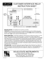
PULSE ISOLATION RELAY
Y2
K2
Y1
K1
Yin1
Kin1
OUTPUT #1
INPUT FROM METER #1
MOUNTING POSITION - The RTR-22+ may be mounted in any position.
POWER INPUT - To power from a 120VAC supply, connect the "hot" lead to the L1 terminal and the neutral to the
NEU terminal. For a 277VAC supply, connect the "hot" lead to the L2 terminal and the neutral to the NEU terminal.
Connect the GND terminal to Ground. Use EITHER L1 or L2, but do not use both at the same time. If Neutral does
not exist at the metering location, connect the NEU and GND terminals BOTH to Ground. Inline fuse recommended.
METER CONNECTIONS - The RTR-22+ has two 2-Wire(Form A) inputs. Connect the "Kin1" and "Yin1" terminals to
the first meter's "K" and "Y" terminals. Connect the "Kin2" and "Yin2" terminals to the second meter's "K" and "Y"
terminals. The RTR-22+'s "Yinx" terminals provide a +13VDC "pulled up" wetting voltage to the meter's Y dry-
contact output terminal. The "Kin" terminal is the common return. When using a polarized pulse output from your
meter, the positive (+) output must go to Yin1 or Yin2, and the negative lead must go to Kin1 or Kin2. Each input
has a Yellow LED which shows the input status. When lit, a pulse is being received from the meter.
OUTPUT - Both 2-wire (Form A) outputs are configured as dry-contact outputs, meaning that no voltage is sourced
from these outputs and thus, the voltage must be supplied by the receiving device. A Green LED shows the output
status. When lit the output is closed. Transient voltage protection for each contact is provided by an on-board MOV
transient suppression device. The outputs are limited to 100 mA max. One-tenth (1/10) Amp fuses are supplied
standard on each output. Switch S1.3 and S1.6 set the Normal or Fixed output mode for Channels 1 and 2
respectively. The Normal mode sets the output pulse width equal to the input's pulse width. The Fixed mode sets
the output for a selected fixed pulse width. More information on Normal and Fixed pulses on pages 2 and 3.
+13VDC sourced to meter
GND
Revision: 4/7/2022
L2 L1 N GND Kin1 Yin1 K1 Y1 K2 Y2
K
Y
METER #1
F1
P/N: 05222-97006B
NEU
120V
277V
OUTPUT #2
RELAY INPUT AND OUTPUT CONFIGURATION - The RTR-22+ has both input and output configuration switches.
Input debouncing time can be set at 50uS, .5mS, 5mS or 20mS, meaning that the input pulse width must be longer
than the filter time to be recognized as a valid pulse. See Page 2.
RTR-22+
Standard Solid State
Kin2 Yin2
K
Y
METER #2
INPUT FROM METER #2
+13VDC sourced to meter
Yin2
Kin2
F2
POWER SUPPLY
CONNECTIONS
Output 1
Output 2
Overflow
Input 1
Input 2
+
+
--
+
-
+
-
See Note on Meter
Polarity on Page 4
WORKING WITH THE RTR-22+ RELAY
OPERATING MODES: The RTR-22+ Repeating Pulse Relay allows the outputs to be
configured for either the "Normal" or "Fixed" pulse output mode. In the Normal mode, the
outputs simply follow the input, and thus, the output pulse widths are equal to input pulse
widths. The Normal mode is the default mode. Set Dip Switch S1.3 DOWN for the Normal
mode on Channel 1. Set Dip Switch S1.6 DOWN for the Normal mode on Channel 2. With
the "normal" output configuration selected, pulse speeds of up to 72,000 pulses per hour (20/
sec) are possible. Figure 1 below shows the timing diagram for the "long" output mode.
As a general guideline, the input pulse rate should not be greater than two times the output
time selected. For example, if a 500mS output time is selected, the input pulse rate should
be no faster than 1 pulse per second. Contact the factory for technical support at (888)272-
9336.
If the Fixed Mode is desired on either or both channels, set Dip Switch S1.3 UP for the Fixed
mode on Channel 1. Set Dip Switch S1.6 UP for the Fixed mode on Channel 2. In the Fixed
output mode, shown in Figure 2 below, an output pulse (K-Y closure) with a selected width
(T1) occurs each time the input is triggered.
T1
Figure 2: 2-Wire SHORT Output Operation
K-Y Out
Kin-Yin Open
Open
Closed
Closed
Figure 1: 2-Wire NORMAL Output Operation
Kin-Yin
K-Y Out
Open
Open
Closed
Closed
Revision: 4/7/22
INPUT FILTER TIMES - The RTR-22+ contains four different input filtering or "debouncing" options.
A pulse received at the RTR-22+' input must be present for at least the specified amount of time to
be considered a valid pulse. If a pulse is received that is less than the filter time, it will be ignored.
Minimum pulse times can be set in the following times: 50uS, .5mS, 5mS or 20mS. For most
electric meter pulse applications, the 20mS input time will be satisfactory. For higher speed
applications with water or gas meters, the minimum input time may need to be reduced. The table
below shows how to set Dip Switches S1.1 and S1.2 to set the input filter or debounce time.
FIXED MODE OUTPUT PERIOD - Output times are independently selectable for each channel
as follows: 50mS, 100mS, 200mS and 500mS. When Switch S1.3 is UP, Channel 1's output is
in the "fixed" mode. Switches S1.4 and S1.5 select the output duration time (Table 2) for
Channel 1. When Switch S1.6 is UP, Channel 2's output is in the "fixed" mode. Switches S1.7
and S1.8 select the output duration time (Table 3). The receiving equipment may require pulses
to be of a given minimum length to be considered a valid pulse. If additional input pulses are
received while a fixed-length output pulse is timing out, the RTR-22+ will store the received
pulse(s) and output them as soon as the time has timed out. The time between pulses is the
same as the specified pulse time, thus giving a 50% duty cycle. Up to 255 output pulses may be
stored. If more than 255 output pulses are stored for either channel, the RED Overflow LED will
light until the pulse count has decremented to a number less than 255. Pulses are not stored in
the event of power failure. Thus, each channel's output register will be reset to zero upon
power-up.
CONFIGURING THE RTR-22+ RELAY
S1.1 S1.2 mS
Up
DwnDwn
Dwn
DwnUp
Up Up
20
5
.5
50uS
S1.4 S1.5 mS
50
100
200
500
Table 1
Table 2 - Chan1
*
Input Filter Time (both inputs)
S1.7 S1.8 mS
50
100
200
500
*
Up
DwnDwn
Dwn
DwnUp
Up Up
Up
DwnDwn
Dwn
DwnUp
Up Up
Table 3 - Chan 2
DIP Switch
23456781
S1
Channel 1 Output Mode - Normal or Fixed
Channel 1 Fixed Mode Output closure time
Channel 2 Output Mode - Normal or Fixed
Channel 2 Fixed Mode Output closure time
RTR-22+ Wiring Diagram
s
4/7/2022 N/A
B
DATE ORIGINAL
LATEST REVISION
SCALE
JOB NO.
REVISIONS
NO. DATE DESCRIPTION
WHB
DRAWNCHECKED
RTR-22+Repeating
Pulse Relay
Wiring Diagram
Brayden Automation Corp./
Solid State Instruments div.
6230 Aviation Circle
Loveland, CO 80538
(970)461-9600
www.solidstateinstruments.com
Water or Gas Meter Application
K1
Y1
K2
Y2
Out 1
Out 2
RTR-22+
Repeating Pulse Relay
Solid
State
Switch
or Reed
Relay Kin
Yin
To Recorder or
EMS
To SCADA,
RTU or other
pulse input
device
Pulse Initator
at Meter
120V
NEU
Power
Supply
Connections
GND
+
-
NPN
Open-
Collector
Bi-Polar
Transistor
+
-
N-Chan
Open-Drain
MosFET
Transistor
+
-
HOT
NEU
GND
Typical Pulse Initiator Types
Kin
Yin
Pulse Input
#2
+
-
+
-
Pulse
Input #1
Non-Polarized
277V HOT
OR
  • Page 1 1
  • Page 2 2
  • Page 3 3
  • Page 4 4

Solid State Instruments RTR-22+ High-Speed Water and Gas Meter Relay User manual

Type
User manual
This manual is also suitable for

Ask a question and I''ll find the answer in the document

Finding information in a document is now easier with AI