Page is loading ...

Home » Solid State Instruments » SOLID STATE INSTRUMENTS CIR-24NG Customer Interface Relay
Instructions
Contents
1 SOLID STATE INSTRUMENTS CIR-24NG Customer Interface
Relay
2 CUSTOMER INTERFACE RELAY INSTRUCTION SHEET
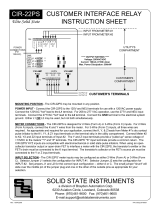
2.1 CIR-24NG Wiring Diagram
2.2 WORKING WITH THE CIR-24NG RELAY
2.3 SSI Universal Programmer
2.4 CIR-24NG Programming
3 Documents / Resources
3.1 References
4 Related Posts
SOLID STATE INSTRUMENTS CIR-24NG Customer Interface Relay
SOLID STATE INSTRUMENTS CIR-24NG Customer Interface
Relay Instructions
Manuals+ — User Manuals Simplified.

CUSTOMER INTERFACE RELAY INSTRUCTION SHEET
MOUNTING POSITION – The CIR-24NG may be mounted in any position. Four mounting holes are provided.
POWER INPUT – For 120VAC power, connect the CIR-24NG to the 120V and NEU terminals. Connect the
120VAC “hot” lead to the 120V terminal. For 208 to 277 VAC operation, use the 277V and NEU terminals.
Connect the 277VAC “hot” lead to the 277V terminal. Connect the NEU terminal to neutral. Connect the GND
terminal to the electrical system ground. Use either L1 OR L2, but not both. The CIR-24NG must be wired Phase
to Neutral, not Phase to Phase. If no true neutral is available, connect both the NEU and GND terminals to the
electrical system ground. The GND terminal MUST be connected. DO NOT leave the GND terminal unconnected.
METER CONNECTIONS – The CIR-24NG is designed for 2-Wire (Form A) or 3-Wire (Form C) inputs. For 2-Wire
(Form A) inputs, connect the K and Y wires from the meter. For 3-Wire (Form C) inputs, connect all three wires, K,
Y and Z. As appropriate and required for your application, connect the K, Y, & Z leads from Meter #1’s dry contact

pulse output to the K, Y, & Z terminals on INPUT #1 of the terminal strip in the utility compartment. Connect Meter
#2 to K, Y and Z terminals of Input #2. The Y and Z input terminals provide a “pulled up” sense voltage of +13VDC
to the meters’ “Y” and “Z” terminals. The CIR-24NG’s “K” input terminals provide a common return. The CIR-
24NG’s KYZ inputs are compatible with electromechanical or solid state pulse initiators. When using an open-
collector transistor output or open-drain FET to interface a meter with the CIR-24NG, the transistor’s emitter pin or
the FET’s source pin must be connected to the K input terminal. The transistor’s collector or the FET’s drain pin
must be connected to the Y or Z input terminals.
INPUT CONFIGURATION – The CIR-24NG’s meter inputs are programmable and may be configured as either 2-
Wire (Form A) or 3-Wire (Form C). See Page 3 for configuring the CIR-24NG’s inputs.
OUTPUT CONFIGURATION – The CIR-24NG’s outputs are programmable and may be configured as either 2-
Wire (Form A) or 3-Wire (Form C). See Page 3 for configuring the CIR-24NG’s outputs.
CIR-24NG Wiring Diagram
Brayden Automation Corp./Solid State Instruments div. 6230 Aviation Circle

Loveland, CO 80538
(970)461-9600
support@brayden.com
www.solidstateinstruments.com
PULSE INPUTS – Two 2-Wire (Form A) or 3-Wire(Form C) pulse inputs are provided on the CIR-24NG. Each
input may be independently programmed as either a Form A or C input. Determine the interface – 2-Wire or 3-
Wire – you will be using with the meter and connect either K and Y for Form A, or K, Y and Z for Form C to the
inputs. Each input supplies the +13VDC wetting voltage to the meter’s dry-contact outputs so no external power
supply is needed. Observe polarity if using a Bi-Polar open-collector transistor or open-drain FET transistor to
drive the inputs of the CIR-24NG, where the Y and Z terminals are positive (+) and the K terminal is negative (-).
Each Y input has a RED LED above the Y input terminal to show when the Y input is active. Each Z input has a
GREEN LED above the Z input terminal to show when the Z input is active.
OUTPUTS – Four three-wire isolated outputs are provided on the CIR-24NG, with output terminals K1, Y1 & Z1;
K2, Y2, & Z2; K3, Y3 & Z3; and K4, Y4 & Z4 and are located in the bottom of the enclosure in the customer
compartment. Outputs are solid state dry-contact type and must be provided with a wetting voltage from an
external source, usually provided by the pulse receiving device. Contacts are rated at 120VAC/VDC MAX and
current limited to 180mA. Transient suppression for the contacts of the solid state relays is provided internally.
Each relay must be assigned or “mapped” to one of the two input channels, using the SSI Universal Programmer
V1.1.0 or later. The CIR-24NG’s outputs may be configured as either a Form A or Form C output. The Form C (3-
Wire) output is the classic “Toggle” output where a pulse is defined as a change-of-state from K-Y continuity to K-Z
continuty or visa versa. LEDs on each output show the output’s status. In Form C output mode, RED and GREEN
LEDs indicate the K-Y closure or K-Z closure, respectively. In the Form A output (2-Wire) “Fixed” mode, only the K
and Y output terminals are used. The RED LED indicates a K-Y closure. In the Form A output mode, the duration
of the closure is programmed for a fixed time or pulse width. There are 8 different pulse widths available.
FORM A PULSE WIDTHS – 8 different pulse widths for Form A closures are available as follows: 50, 100, 200,
500, 1000, 2000, 5000, and 10000 mS. The fixed output length can be disabled by entering Disabled from the
pulldown list. When the fixed length is disabled the output pulse width mirrors the input pulse width, so it is the
same.
MAXIMUM POWER DISSIPATION OF OUTPUTS – Output devices are rated at a maximum of 1500 mW. Care
should be taken to insure that the wetting voltage used across the output device times the current (or burden) of
the input of the downstream device, does not exceed the maximum power output dissipation of 1500mW.
Normally this is not a problem since most downstream instrumentation devices are high impedance and present a
very low burden, usually less than 10mA. For example, if 120VAC is used, the maximum allowable current across
the output is 12.5 mA. If 12VDC is used, the maximum current allowable across the output is approximately
125mA, well under the 180mA current rating of the device. Therefore, the maximum dissipation when using 12V is
1500mW since the current is limited to .125 Amp. Calculate the maximum current using the following formula:
1500milliWatts / Voltage = Max. Current (burden) in milliamps. Adjust the voltage or current used across the
output to insure that the maximum power dissipation, voltage and current maximums are not exceeded.
FUSES – Each output has its own Fuse rated at 250mA F1, F2, F3 and F4 correspond to outputs 1, 2, 3, and 4,
respectively. Maximum fuse ratings are designated on the silkscreen under or adjacent to each fuse position.
OPERATING MODES – The CIR-24NG has five operating modes as follows:
Form C In/Form C Out – Pass thru; Output closure time equals Input closure time.
Form A In/Form A Out – Pass thru; Output closure time equals Input closure time.
Form A In/Form A Out – Pass thru with Fixed Width Output timing.
Form A in/Form C Out – Conversion Mode; Output Changes each time the input changes. 5.)
Form C In/ Form A Out – Conversion Mode with Fixed Width Output timing.
These modes are assignable by the designated Input and Output Combination programmed into the CIR-24NG.

Each output is therefore assigned a mode based on the Input Form, the Output Form and the pulse width
assigned, if applicable. Since each output is independently assignable, two or more outputs mapped to an input
can operate in different modes.
WORKING WITH THE CIR-24NG RELAY
OPERATING MODES: The CIR-24NG Programmable Customer Interface Relay has 5 operating modes. Three
are “Pass-Thru” modes while two are “Conversion” modes.
Mode 1 – Form C In/Form C Out: In this Pass-Thru mode, both the input and the output are set to Form C (3-
wire) mode. The Form C output(s) follow the Form C input. Output pulse widths equal the input pulse widths. The
RED dot shown in the timing figures indicate a K-Y closure and the output’s RED LED is on. The Green dot in the
timing figures indicate K-Z closure and the output’s Green LED is on.
Mode 2 – Form A In/Form A Out: In this Pass-Thru mode, both the input and the output are set to Form A (2-wire)
mode and the fixed Output Pulse Width is disabled. The Form A output(s) follow the Form A input. Output pulse
widths equal the input pulse widths.
* Zin is not used in the 2-wire (Form A) input mode.
Mode 3 – Form A In/Form A Out with fixed Output Pulse Width: In this Pass-Thru mode, both the input and the
output are set to Form A (2-wire) mode. The Form A output(s) follow the Form A input, but close for the selected
pulse width duration.

In this mode the Form A output is set to 50mS, up to 10,000mS, so output pulses are a fixed width as defined by
the Pulse Width entry box. If input pulses are faster than output pulses, an overflow can occur in this mode. That
means that output pulses cannot keep up with input pulses because of the timing constraints of the fixed pulse
width. In the event that this happens, the Overflow LED corresponding to the output(s) affected would come on.
Pick a shorter Output Pulse Width or disable the fixed pulse width, then click on <Send Parameters>, and then
click on <Reset Overflow>.
Mode 4 – Form A In/Form C Out: In this Conversion mode, the Input is set to Form A (2-Wire) and the output is
set to Form C (3-wire). Upon each closure of the Form A input, the Form C output changes state to the opposite
state. This conversion function allows the input and output pulse values to be equal.
Mode 5 – Form C In/Form A Out with fixed Output Pulse Width: In this Conversion mode, the input is set to Form
C (3-Wire) and the output is set to Form A (2-wire). The Form A output(s) gives a fixed width pulse upon the
change of state of the Form C input. An overflow may occur if the pulse rate is too high and the output pulse width
is too long. This conversion function allows the input and output pulse values to be equal.

In this mode the Form A output is set to a fixed pulse width. The Fixed Pulse Width cannot be disabled in this
mode as it is an illegal condition. The output must be programmed with a fixed output pulse width. If an overflow
occurs, shorten the output pulse width time.
Mapping each Output to an Input: The four outputs of the CIR-24NG must be assigned, or “mapped”, to an input
that they follow. Any output may be mapped to either input. Common configurations are the “13+11” where
outputs 1 through 3 are mapped to Input #1; Output #4 is mapped to Input #2. This configuration is common when
multiple devices each receive the same isolated pulse on outputs #1 to #3 and an End-Of-Interval pulse is on
output #4.
All four outputs may be assigned to one input giving four isolated contacts. The unused input may be disabled.
Another popular configuration is the “24” where two outputs each follow one input. For example outputs #1 and #2
follow input #1 and outputs #3 and #4 fol low Input #2. This configuration is used for delivered and received kWh
pulses, or for kwh and kVARh pulses.
The factory default configuration is as follow:
Outputs #1 and #2 are mapped to input #1, Form C Input/Form C Outputs
Outputs #3 and #4 are mapped to Input #2, Form C Input/Form C Outputs
Contact the factory for technical support at (888)272-9336.
SSI Universal Programmer
The SSI Universal Programmer is a windows-based programming utility for the CIR-24NG Series and other SSI
products. Download the SSI Universal Programmer from the SSI website at
www.solidstateinstruments.com/sitepages/downloads.php. There are two versions available for download:
Windows 10 and Windows 7 64-bit Version 1.1.0 or later
Windows 7 32-bit V1.1.0 or later
If you are using Windows 7, check your computer first to insure you download the right version.

Reset Factory Defaults- You can reset the CIR-24NG to the factory defaults by pulling down the File menu and
selecting Reset Factory Defaults. This will put the CIR-24NG back into Operating Mode #1.
CIR-24NG Programming
Setting the CIR-24NG’s Settings
Set the CIR-24NG’s input and output pulse types, input to output mapping and the pulse timing by using the USB
[Type B] Programming Port on the CIR-24NG board. All system settings are configured using the USB
Programming Port. Download the SSI Universal Programmer software V1.1.0 or later, available as a free
download from the SSI website. Alternately, the MPG-3 can be programmed using a terminal program such as
TeraTerm. See “Setting up the Serial Port” on Page 9.
Programmer Startup
Before starting the program connect the USB cable between your computer and the CIR-24NG. Make sure that
the CIR-24NG is powered up. Click on the SSI Universal Programmer icon on your desktop to start the program.
In the upper left corner you will observe two Green simulated LEDs, one indicating that the USB cable is
connected and the other that the CIR-24NG is connected to the programmer. Make sure both Green LED’s are
“lit” .
Input Form

The CIR-24NG has two inputs. Each input can be designated as a Form A (2-Wire) or Form C (3-Wire) input. Set
the each input for the number of wires (or “form”) that is connected to the meter. If three wires are coming from the
meter set the input to Form C. If only two wires are used, set to Form A. Use the pull-down menu to select the
correct input Form. See the screen shot of the SSI Universal Programmer on Page 7. Once you have selected the
desired input Forms click <Save Parameters>.
Output Form
The CIR-24NG has four independent 3-Wire outputs. Each output can operate in the legacy 3-Wire (Form C)
mode or the 2-Wire (Form A) mode. Red and Green Output LEDs show the pulse output status. See additional
information on Page 5. Use the Output Form pull-down menus for each output and select “C” in the pulldown and
click <Save Parameters>.
Use the Output Form box to enter “A” to select the FORM A Fixed mode. In the Fixed mode, only the K-Y output is
used. This is the standard 2-Wire system where the output contact is normally-open until such time as a pulse is
generated. When a pulse is generated, the contact is closed for either the same duration as the input or for a the
fixed time interval, in milliseconds, selected in the Form A Width box. Form A mode is generally associated with
Energy (kWh) measuring systems. Select “A” in the Output Form pulldown box and click <Save Parameters>.
Form A Pulse Width
If you are using an output of the CIR-24NG’s in the Form A (Fixed) Mode, set the output closure time or pulse
width, selectable at 25mS, 50mS, 100mS, 200mS, 500mS,1000mS, 2000mS, 5000mS or 10000mS (1 second)
using the Form A Width box. Upon a pulse being generated, the K-Y terminals of a Form A output will close for the
selected number of milliseconds and light the RED Output LED only. This setting applies only to the Form A
output mode, and does not affect the toggle output mode. Use the shortest closure time possible that will be
reliably received by the pulse receiving equipment, so as not to unnecessarily limit the output’s maximum pulse
rate. You can also select Disable in the pulldown menu which causes the output to close for the same duration as
the input. Select the desired pulse width from the pulldown in the Form A Width box and click <Save Parameters>.
If the output type selected is Form C, the Form A Pulse Width box will be grayed out.
Output to Input Mapping
The CIR-24NG contains the ability to “map” each of the four outputs to either one of the two inputs. That means
that all kinds of flexible configurations can be programmed using the Map Output to Input pulldown menus. Select
which input you want each output to follow. As you can see in the example on Page 7, Outputs #1 and #3 are
mapped to follow Input #1 and Outputs #2 and #4 are mapped to follow Input #2. Once you have selected Input 1
or Input 2 from each output’s pulldown menu, click on <Save Parameters>.
Read Parameters
To read back the current settings from a CIR-24NG at any time, simply click on <Read Parameters>. The current
settings in the CIR-24NG will be displayed.
Reset Overflow
If an output in Form A mode accrues a number of pulses greater than 127, an Overflow condition occurs. This
simply means that given the timing constraints on the output primarily from the Form A Pulse Width, the output
cannot keep up outputting pulses at the desired speed. In this event, change the Form A Pulse Width to a smaller
number, click <Save Parameters> and then click <Reset Overflow>. The Overflow indicators for the output(s)
which are in overflow condition and the corresponding register will be reset.
Capturing Data with the SSI Universal Programmer
It is also possible to Log or capture data using the SSI Universal Programmer. When the logging function is
enabled, the information received from the Module or the meter can be logged to a file. This will be helpful in trying
to troubleshoot intermittent connectivity issues. Click on the Capture pulldown menu and select setup. Once a file
name and directory have been designated, click on Start Capture. To end the Logging, click on Stop Capture.
Special Note: Even though there are three wires (K,Y, & Z) on pulse outputs, it is common to use K and Y, or K
and Z, for many two-wire systems that require or desire a generally symmetrical 50/50 duty cycle pulse at any
given time. The toggle mode is used for systems that are doing demand monitoring and control and need
regularly spaced or “symmetrical” pulses. If you are in FORM C Toggle output pulse mode, and your pulse
receiving device uses only two wires, and the pulse receiving device only counts the output’s contact closure as a

pulse(not the opening), then the 3-Wire pulse value must be doubled in the Pulse Receiving Device.
Programming with a Terminal Program
The CIR-24NG can be programmed using a terminal program like Tera Term, Putty, Hyperterminal or ProComm.
Set the baud rate for 57,600, 8 bit, 1 stop bit and no parity. Be sure that the Receive is set for CR+LF and turn on
Local Echo.
List of CIR-24NG Commands (?)
For help in selecting or using the serial commands with the CIR-24NG, simply press the H or ? key. The serial link
on the CIR-24NG will return a full list of the commands.
‘INxy<CR>’ – Set input, x-input(1-2) y=Type(C,A)
‘OUTxy<CR>’ – Set output, x-output(1-4) y=Type(C,A)
‘MAPxy<CR>’ – Map Output/Input, x-output(1-4) y=Input(1-2)
‘Wxy<CR>’ – Set pulse width, x-output(1-4), y-Pulse Width(0-8) (See below)
‘CX<CR>’ – Clear overflow (X=1-4)
‘R<CR>’ – Read Parameters
‘Z<CR>’ – Set Factory Defaults
‘V<CR>’ – Query Firmware version
Form A Pulse Width
‘Wxy<CR>’- Pulse Width in Form A mode, milliseconds – 25 to 10000mS, 100mS default;
Form A Pulse Width Selections:
‘wx0<CR>’ or Wx0<CR>’ – 25mS Closure
‘wx1<CR>’ or ‘Wx1<CR>’ – 50mS Closure
‘wx2<CR>’ or ‘Wx2<CR>’ – 100mS Closure
‘wx3<CR>’ or ‘Wx3<CR>’ – 200mS Closure
‘wx4<CR>’ or ‘Wx4<CR>’ – 500mS Closure
‘wx5<CR>’ or ‘Wx5<CR>’ – 1000mS Closure
‘wx6<CR>’ or ‘Wx6<CR>’ – 2000mS Closure
‘wx7<CR>’ or ‘Wx7<CR>’ – 5000mS Closure
‘wx8<CR>’ or ‘Wx8<CR>’ – 10000mS Closure
CIR-24NG Programmable Relay.vsd
Documents / Resources
SOLID STATE INSTRUMENTS CIR-24NG Customer Interface Relay [pdf] Instructions
CIR-24NG, Customer Interface Relay, Interface Relay, Customer Relay, Relay
References

/